1
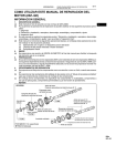
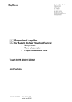
Raytheon Anschütz GmbH Postfach 1166 D -- 24100 Kiel Germany Tel +49--4 31--30 19--0 Fax +49--4 31--30 19--501 Email [email protected] www.raytheon--anschuetz.de Change Over Box Type 138-119 Operator-- and Service--Manual 1 2 3 4 5 Description Function of the Change Over Box Installation and Stetting to Work Change Over Box in the STD22--System Maintenance and Repair 3769DOC000002 Edition: April 06, 2005 Revision: Revision: December 08, 2005 September 14, 2009 Weitergabe sowie Vervielfältigung dieser Unterlage, Verwertung und Mitteilung ihres Inhaltes nicht gestattet, soweit nicht ausdrücklich zugestanden. Zuwiderhandlungen verpflichten zu Schadenersatz. Copying of this document, and giving it to others and the use or communication of the contents thereof, are forbidden without express authority. Offenders are liable to the payment of damages. Toute communication ou reproduction de ce document, toute exploitation ou communication de son contenu sont interdites, sauf autorisation expresse. Tout manquement à cette règle est illicite et expose son auteur au versement de dommages et intérêts. Sin nuestra expresa autorización, queda terminantemente prohibida la reproducción total o parcial de este documento, así como su uso indebido y/o su exhibición o comunicación a terceros. De los infractores se exigirá el correspondiente resarcimiento de daños y perjuicios. Change Over Box 138--119 COMPASS STD 22 SAFETY INFORMATION " Caution! Pay attention whilst Maintenance and Repair. Avoid contact with cable under load. Adhere to respective safety regulations, as there are VDE, BGV A2, OSHA 1919 and other national and international safety standards. This Change Over Box is not equipped with an interlocking mechanism. Before Maintenance or Repair the device has to be separated from supply voltage. " ATTENTION! Maintenance and Repair have to be performed only by trained personnel, which is familiar with the safety requests of this device. Determinations for handling of electrostatic devices must be adhered to. To remove or to add an assembly or a printed circuit board under load may lead to severe faults of the device. Insert no fuses with other technical data than the prescribed ones. Edition: April 06, 2005 I 3769DOC000001 Change Over Box 138--119 COMMERCIAL NOTES Change Over Box in application with GG--R and GGM--R " Not all Status messages/Alarms are displayed at the Operator Unit. It has to be assured that all the alarm--contacts of both Distribution Units (system Failure) are connected to an external Alarm Units. " The DV--Bus is not switched--over by the Change Over Box. " A difference alarm (G/G or G/M) does not lead to a switch--over in the Change Over Box. " At one of the two Operator Units the automatic switch--over--function G --> G or G --> M has to be set. Thus ensures a switching --over from a failed selected sensor to the next heading sensor in function. " Connected repeater should be configured in such a manner, that heading from a gyro is as well indicated as heading from a magnetic sonde. " Information and/or data to operate the compass have to be stored twice (for each Distribution Unit), by operating the Change over Switch into the respective position. 3769DOC000001 II Edition: December 08, 2005 Change Over Box 138--119 COMPASS STD 22 SAFETY INFORMATION and Notes . . . . . . . . . . . . . . . . . . . . . . . . . . . . . . . . . . . . . . . . . . . . . I 1 Description . . . . . . . . . . . . . . . . . . . . . . . . . . . . . . . . . . . . . . . . . . . . . . . . . . . . . . 1 1.1 1.2 1.3 1.3.1 1.3.2 Change Over Box Type 138--119 . . . . . . . . . . . . . . . . . . . . . . . . . . . . . . . . . . . . . . . . . . . . . . . . . Change Over Switch Type 124--187 . . . . . . . . . . . . . . . . . . . . . . . . . . . . . . . . . . . . . . . . . . . . . . Technical Data . . . . . . . . . . . . . . . . . . . . . . . . . . . . . . . . . . . . . . . . . . . . . . . . . . . . . . . . . . . . . . . . Change Over Box . . . . . . . . . . . . . . . . . . . . . . . . . . . . . . . . . . . . . . . . . . . . . . . . . . . . . . . . . . . . . . Change Over Switch . . . . . . . . . . . . . . . . . . . . . . . . . . . . . . . . . . . . . . . . . . . . . . . . . . . . . . . . . . . 1 3 4 4 4 2 Principle of function Change Over Box . . . . . . . . . . . . . . . . . . . . . . . . . . . . 5 2.1 2.1.1 2.1.2 2.1.3 Principle “Change Over Box in the STD22--System” . . . . . . . . . . . . . . . . . . . . . . . . . . . . . . . . Switch position “Automatic” . . . . . . . . . . . . . . . . . . . . . . . . . . . . . . . . . . . . . . . . . . . . . . . . . . . . . Switch position “System 1” . . . . . . . . . . . . . . . . . . . . . . . . . . . . . . . . . . . . . . . . . . . . . . . . . . . . . . Switch position “System 2” . . . . . . . . . . . . . . . . . . . . . . . . . . . . . . . . . . . . . . . . . . . . . . . . . . . . . . 5 8 9 9 3 Installation and Setting to Work . . . . . . . . . . . . . . . . . . . . . . . . . . . . . . . . . . . 11 3.1 3.1.1 3.1.2 3.2 3.2.1 3.2.1.1 3.2.2 3.3 3.3.1 3.3.1.1 3.3.1.2 3.3.1.3 3.4 3.5 General Comments . . . . . . . . . . . . . . . . . . . . . . . . . . . . . . . . . . . . . . . . . . . . . . . . . . . . . . . . . . . . General remarks to establish cable connections . . . . . . . . . . . . . . . . . . . . . . . . . . . . . . . . . . . General information about establishing an earth connection . . . . . . . . . . . . . . . . . . . . . . . . . Connecting the Change Over Box to the STD22--System . . . . . . . . . . . . . . . . . . . . . . . . . . . . Connecting the supply voltage . . . . . . . . . . . . . . . . . . . . . . . . . . . . . . . . . . . . . . . . . . . . . . . . . . . Voltage supply of the connected receiver . . . . . . . . . . . . . . . . . . . . . . . . . . . . . . . . . . . . . . . . . . Connecting of signal lines . . . . . . . . . . . . . . . . . . . . . . . . . . . . . . . . . . . . . . . . . . . . . . . . . . . . . . . Setting to work . . . . . . . . . . . . . . . . . . . . . . . . . . . . . . . . . . . . . . . . . . . . . . . . . . . . . . . . . . . . . . . . Special features for operating a system with a Change over Box . . . . . . . . . . . . . . . . . . . . . Special features for DV bus operation . . . . . . . . . . . . . . . . . . . . . . . . . . . . . . . . . . . . . . . . . . . . Special features for connected Rate Gyro . . . . . . . . . . . . . . . . . . . . . . . . . . . . . . . . . . . . . . . . . Special features for connected NAV Manager/ Data Manager . . . . . . . . . . . . . . . . . . . . . . . . Function test of Change Over Box and Change Over Switch . . . . . . . . . . . . . . . . . . . . . . . . . Switching OFF the Change Over Box . . . . . . . . . . . . . . . . . . . . . . . . . . . . . . . . . . . . . . . . . . . . . 11 13 15 16 16 16 17 19 20 20 21 21 22 23 4 Change Over Box application in the STD22--System . . . . . . . . . . . . . . . . 24 4.1 4.2 4.3 4.4 4.4.1 4.4.2 4.4.3 Change Over Box application in the STD22 GG--R Gyro Compass System . . . . . . . . . . . . Change Over Box application in the STD22 GGM--R Gyro Compass System . . . . . . . . . . . Redundant Voltage Supply . . . . . . . . . . . . . . . . . . . . . . . . . . . . . . . . . . . . . . . . . . . . . . . . . . . . . . Error message “System Failure” . . . . . . . . . . . . . . . . . . . . . . . . . . . . . . . . . . . . . . . . . . . . . . . . . “System Failure” in switch position “Automatic” . . . . . . . . . . . . . . . . . . . . . . . . . . . . . . . . . . . . . “System Failure” in switch positions “Sys1” and “Sys2” . . . . . . . . . . . . . . . . . . . . . . . . . . . . . . Status messages/ Error messages . . . . . . . . . . . . . . . . . . . . . . . . . . . . . . . . . . . . . . . . . . . . . . . 24 26 28 29 30 31 32 5 Maintenance and Repair . . . . . . . . . . . . . . . . . . . . . . . . . . . . . . . . . . . . . . . . . . 34 5.1 5.2 5.2.1 5.2.2 5.2.3 5.2.4 5.2.4.1 5.2.4.2 5.3 Maintenance . . . . . . . . . . . . . . . . . . . . . . . . . . . . . . . . . . . . . . . . . . . . . . . . . . . . . . . . . . . . . . . . . . Repair . . . . . . . . . . . . . . . . . . . . . . . . . . . . . . . . . . . . . . . . . . . . . . . . . . . . . . . . . . . . . . . . . . . . . . . . Safety instructions . . . . . . . . . . . . . . . . . . . . . . . . . . . . . . . . . . . . . . . . . . . . . . . . . . . . . . . . . . . . . Trouble shooting in a STD22 Gyro Compass System . . . . . . . . . . . . . . . . . . . . . . . . . . . . . . . Fuses in the Change Over Box . . . . . . . . . . . . . . . . . . . . . . . . . . . . . . . . . . . . . . . . . . . . . . . . . . Service . . . . . . . . . . . . . . . . . . . . . . . . . . . . . . . . . . . . . . . . . . . . . . . . . . . . . . . . . . . . . . . . . . . . . . . Exchanging of fuses . . . . . . . . . . . . . . . . . . . . . . . . . . . . . . . . . . . . . . . . . . . . . . . . . . . . . . . . . . . Exchanging of relays . . . . . . . . . . . . . . . . . . . . . . . . . . . . . . . . . . . . . . . . . . . . . . . . . . . . . . . . . . . Parts list . . . . . . . . . . . . . . . . . . . . . . . . . . . . . . . . . . . . . . . . . . . . . . . . . . . . . . . . . . . . . . . . . . . . . . 34 34 34 35 35 36 37 38 38 Edition: April 06, 2005 III 3769DOC000001 Change Over Box 138--119 6 Error performance . . . . . . . . . . . . . . . . . . . . . . . . . . . . . . . . . . . . . . . . . . . . . . . . 39 6.1 6.2 6.3 6.4 6.5 6.6 6.7 6.8 Gyro 1 fails . . . . . . . . . . . . . . . . . . . . . . . . . . . . . . . . . . . . . . . . . . . . . . . . . . . . . . . . . . . . . . . . . . . Gyro 2 fails . . . . . . . . . . . . . . . . . . . . . . . . . . . . . . . . . . . . . . . . . . . . . . . . . . . . . . . . . . . . . . . . . . . Distribution Unit 1 fails . . . . . . . . . . . . . . . . . . . . . . . . . . . . . . . . . . . . . . . . . . . . . . . . . . . . . . . . . . Distribution Unit 2 fails . . . . . . . . . . . . . . . . . . . . . . . . . . . . . . . . . . . . . . . . . . . . . . . . . . . . . . . . . . Power Supply 1 fails . . . . . . . . . . . . . . . . . . . . . . . . . . . . . . . . . . . . . . . . . . . . . . . . . . . . . . . . . . . Power Supply 2 fails . . . . . . . . . . . . . . . . . . . . . . . . . . . . . . . . . . . . . . . . . . . . . . . . . . . . . . . . . . . Magnetic sonde 1 fails . . . . . . . . . . . . . . . . . . . . . . . . . . . . . . . . . . . . . . . . . . . . . . . . . . . . . . . . . . Magnetic sonde 2 fails . . . . . . . . . . . . . . . . . . . . . . . . . . . . . . . . . . . . . . . . . . . . . . . . . . . . . . . . . . 40 41 41 41 42 42 43 43 Drawings Change Over Box Dimensional Drawing 138--119.HP005 Change Over Box Bauschaltplan / Wiring Diagram 138--119.HP008 Change Over Switch Dimensional Drawing 124--187.HP005 Block diagram STD 22 GGM--R, Signal flow Block diagram STD 22 GG--R, Power Distribution 3769DOC000001 IV 10--BD--D--X00014--C 10--BD--D--X00013--C Edition: April 06, 2005 Change Over Box COMPASS STD22 138--119 1 Description 1.1 Change Over Box Type 138--119 The Change Over Box Type 138--119 is used to operate redundantly two compass--systems. It serves to switch--over automatically or manually of up to 12 different signals. Compass Compass System 1 System 2 ChangeOver Box 138--119 Heading Receiver Figure 1: Principle of switching--over 3769DOC000002 1 Edition: Sept. 14, 2009 Change Over Box 138--119 Bottom view top view Figure 2: Change Over Box Type 138--119 Edition: April 06, 2005 2 3769DOC000002 Change Over Box COMPASS STD22 138--119 1.2 Change Over Switch Type 124--187 The Change Over Switch Type 124--187 is applied in combination with the Change Over Box to allow the redundant operation (standard operation) of the compass equipment (Change Over Switch position “Automatic”). During standard operation a switching--over to the other system takes place if a fault occurs. By manual switching--over to position “Sys1” or “Sys2” signal outputs are assigned to the respective Distribution unit constantly. Auto-matic Sys 1 Sys 2 front view side view (mounting position) Figure 3: Change Over Switch Type 124--187 3769DOC000002 3 Edition: April 06, 2005 Change Over Box 138--119 1.3 Technical Data 1.3.1 Change Over Box See also Change Over Box Dimensional Drawing 138--119.HP005 at the appendix. Dimensions: appr. 605 mm x153 mm x250 mm Weight: appr. 8 kg Mounting mode: Wall mounted Internal Protection: IP22 (Wall mounted, Cable inlet below) Main Fuse (Terminal board): 2 x T10 A, 250 V Nominal voltage range (Relays) 18 -- 36 VDC Operating voltage (Mains supply) 24 VDC Power consumption (Relays) max. 1 A Number of Relays 18 ( 3 Relay--Groups with 6 Relays each) Number of Relay contacts 4 nc* and 4 no* for each Relay (in total 72 ) *nc -- normally closed, no -- normally open 1.3.2 Change Over Switch The Change Over Switch is a 4--pole switch with three switch--positions. Dimensions appr. 96 mm x120 mm x96 mm Weight appr. 0.8 kg Edition: April 06, 2005 4 3769DOC000002 Change Over Box COMPASS STD22 138--119 2 Principle of function of the Change Over Box 2.1 Principle “Change Over Box in the STD 22--System” In the redundant system of the Standard STD 22 the Change Over Box and the Change Over Switch are used to switch--over between the output signals of both systems. The diagram below shows the principle of switching--over including the fault monitoring of ”C Out” 24V DC 24V DC ”Relay A” Change Over Switch ”Automatic” ”Sys1” ”Sys2” ”System Failure” ”A Out” ”Relay B ”B Out” ”Relay C” ”B In2” ”C In1” ”A In2” ”B In1” ”A In1” ”C” ”D” ”B” ”A” DU 1 ”System Failure” Compass System 1 Change Over Box ”C In2” ”Relay D” ”D” ”C” ”B” ”A” DU 2 Compass System 2 Compass system 1. Figure 4: Principle of switching--over in the compass system STD 22 3769DOC000002 5 Edition: Sept. 14, 2009 Change Over Box 138--119 Caption: “A” = Signal “A” “B” = Signal “B” “A In1” = Signal “A” at the output “System 1” “B In2” = Signal “B” at the output “System 2” “A Out” = switched signal “A” “B Out” = switched signal “B” “System Failure” = Failure message of “compass system 1” NOTE Some of the relay outputs are led via fuses from the Change Over Box to the connected receivers. This fuse protection serves to prevent effects to the Change Over Box in case of a fault in a connected heading receiver. NOTE! A.m. Figure 4 shows a principle of switch--over The actual connections are shown in the appended wiring diagrams. The switch--over--relays in the Change Over Box are controlled with a switching voltage of 24 V DC. This switching voltage is generated in the Change Over Box, led to the Change Over Switch. The operation of the Change Over Box is possible with three different switch positions: -- Automatic switch--over because of a fail. -- Manual switch--over to system 1. -- Manual switch--over to system 2. Edition: April 06, 2005 6 3769DOC000002 Change Over Box COMPASS STD22 138--119 Below mentioned table shows an overview of the possible switch positions and the appertaining operation modes. Pos. Switch position Mode Status 1 “Auto-matic” “Normal mode” -- Output of “System 1” at the outputs of the Change Over Box. -- In case of a fault in “System 1” -- switching--over to “System 2” 2 “Sys1” “System 1” -- Output of “System 1” at the outputs of the Change Over Box. 3 “Sys2” “System 2” -- Output of “System 2” at the outputs of the Change Over Box. Further information to the switching positions is given in the following sections. 3769DOC000002 7 Edition: April 06, 2005 Change Over Box 138--119 2.1.1 Switch position “Automatic” In the normal mode (switch position “Automatic”) the switching--over of the output signals of compass system 1 are carried out of the Distribution Box (DU1) via the Change Over Box (see Figure 4). All relays of the Change Over Box are dropped out. The DUs of both compass systems communicate via the CAN bus. But only the DU1 is “active” and its output signals (”A In1”, “B In2” etc.) are switched to the connected receiver (”A Out”, “B Out” etc.). If a fault is detected in the DU1 (”System Failure”), the Change Over Box switches over to the DU2 automatically. This is affected by closing the contact of relay “System Failure” in the DU1. Thus the 24 V DC switching voltage is switched to the Change Over Box via the Change Over Switch. All relays of the Change Over Box operate and switch the outputs of the Change Over Box from the signal outputs of the DU1 (for example “A In1”) to the signal outputs of the DU2 (for example “A In2”). At the same time the error message “System Failure” can be detached as a 24 V DC potential from the Change Over Switch for external applications. This switch--over function is not activated by a fault in the Distribution Unit 2. After repair and setting into operation again the output signals of the compass system 1 are switched to the output of the Change Over Box, No additional measures are necessary. ATTENTION! It can happen that there is a desynchronisation of the 6--steps/degree signal after switching--over -- either manual or automatically. Edition: April 06, 2005 8 3769DOC000002 Change Over Box 138--119 2.1.2 COMPASS STD22 Switch position “System 1” If the Change Over Switch is switched into position “Sys 1” manually, the signal outputs of the compass system 1 are carried out of the Distribution Box via the Switch Over Box (see Figure 4). The connection of the relay “System Failure” of system 1 (DU 1) via the Change Over Switch is not used. The 24 V DC potential is not switched to the relays of the Change Over Box. All relays are dropped out. ATTENTION! There is no automatic switch--over to DU 2 if the DU1 fails (”System Failure”). The Change Over Box does not switch signals from the outputs of the Distribution Unit 1 to the heading receivers. 2.1.3 Switch position “System 2” If the Change Over Switch is switched into position “Sys 2” manually, the signal outputs of the compass system 2 are carried out of the Distribution Box via the Switch Over Box (see Figure 4).The connection of the relay “System Failure” of system 2 (DU 2) via the Change Over Switch is not used. The 24 V DC potential is fed from the Change Over Box via the Change Over Switch and back again to the Change Over Box. All relays operate. ATTENTION! There is no automatic switch--over to DU 1 if the DU2 fails (”System Failure”). The Change Over Box does not switch signals from the outputs of the Distribution Unit 2 to the heading receivers. 3769DOC000002 9 Edition: April 06, 2005 Change Over Box 138--119 intentionally left blank Edition: April 06, 2005 10 3769DOC000002 Change Over Box COMPASS STD22 138--119 3 Installation and Setting to Work 3.1 General Comments Caution! During installation, ensure that there are no live cables. If necessary, carry out measurements and switch off the respective power distribution. ATTENTION! Installation is to be performed only by trained personnel, which is familiar with the safety requirements of this device. Installation of the Change Over Box and the Change Over Switch have to be performed according to appended wiring diagrams. 3769DOC000002 11 Edition: April 06, 2005 Change Over Box 138--119 For installation of the Change Over Box see Dimensional Drawing 138--119.HP005. Additional criteria for the mounting location: -- The Change Over Box may not be installed within an oil vapour area. -- Not down in the bilge. -- Keep distance to other equipment to perform cabling to the Change Over Box. -- The cover of the Change Over Box has to be removable to the front -- The attachment has to be seaworthy, shock--proof and resistant to vibrations. -- The Change Over Box may not be exposed to dripping water (according to its internal protection IP 22 -- cable inlets below-- ). Edition: April 06, 2005 12 3769DOC000002 Change Over Box COMPASS STD22 138--119 3.1.1 General remarks to establish cable connections NOTE! While closing again the housing after a repair or an installation, the cover has to be set carefully. The seal may not be crushed, if necessary push the sidewall slightly. In order to ensure that the system operates correctly, it is essential to follow the procedures described below for establishing cable connections. 1. Strip off approx. 180 mm of the cable (depending on the distance terminal board or relay to the cable inlet). Make sure not to damage the shielding. 2. Strip off the shielding to a remainder of approx. 15 mm. approx. 15 mm approx. 180 mm Figure 5: How to strip a connection cable 3769DOC000002 13 Edition: April 06, 2005 Change Over Box 138--119 3. Screw the cable gland out from the Change Over Box and push the screw connection components over the cable. It is absolutely necessary that the sequence (as shown in Figure 6 ) is adhered to. 4. Check the cone and counterpart on the earthing insert for corrosion and if necessary remove corrosion using an appropriate process (emery board). 5. Push the counterpart of the earthing insert as far as the end of the cable shield. 6. Push the earthing insert cone below the shielding against the counterpart. Make sure that the shielding is evenly over the cone. Wall and DIN socket Earthing insert -- Cone -- Counterpart Seal + Strain relief Shielding Washer Counternut Figure 6: Making a cable entry 7. Insert the earthing insert, the seal with and the washer into the cable gland, place the counter nut on top and hand--tighten. 8. Strip the cable cores to a length of approx. 15 mm, twist slightly and clamp on the cable end sleeves. Connect the cable strands in the Change Over Box as shown in the appended wiring diagrams. Hand--tighten the terminal screws concerned. 9. Check the connection is firm by pulling slightly. Edition: April 06, 2005 14 3769DOC000002 Change Over Box COMPASS STD22 138--119 3.1.2 General information about establishing an earth connection In order to comply with the stringent EMC requirements, please abide by the information given below regarding cable connections. Use the cable types specified in the appended wiring diagrams. ATTENTION! It is essential to ensure that these connections have a common reference to ship‘s earth. Any additional components (options -- if there are) must also be connected to the common earth! Figure 7: Establishing an earth connection All earth connections must be made as shown in Figure 7 -- The earthing cable attached to the bracket must have a cross--section of minimum 1,5 mm2. -- The cable bracket should be mounted between two toothed washers. -- Earth connections must be free of corrosion and well fastened. 3769DOC000002 15 Edition: 3 Change Over Box 138--119 3.2 Connecting the Change Over Box to the STD22--System Detailed terminal designations, cable connections, cable types are to be established according to the wiring diagram (138--119.HP008), the actual cable and connection diagrams as well as the manual of the Distribution Unit 138--118. 3.2.1 Connecting the supply voltage (see also section 4.3 -- Redundant voltage supply). Voltage supply is effected by connecting the 24 V DC supply voltage via 2 fuses ( 6,3 A, 24 V) to the terminal board of the Change Over Box. (see also Change Over Box wiring Diagram 138--119.HP008 ). 3.2.1.1 Voltage supply of the connected receiver The connected receivers can be supplied with operating voltage (24 V DC) out of the Change Over Box independent of the signal lines. For that purpose supply lines to the receivers have to be connected at the terminal board (terminals 3 to 13) of the Change Over Box. These terminals are fuse--protected. Terminals 3 to 10 are fitted with fuses 1 A, 24 V (it is to connect the supply voltage for only one receiver). Terminal 11 to 13 are fitted with fuses 2 A, 24 V (it is to connect the supply voltage for up to two receivers). Edition: April 06, 2005 16 3769DOC000002 Change Over Box COMPASS STD22 138--119 3.2.2 Connecting of the signal lines The output signal lines of DU 1 are connected to the break contact element of the respective relay, because of a switching through of the dropped--out relay status. The output signal lines of DU 2 are connected to the normally open contacts of the relay, because of lead over from the Change Over Box after switching--over to the activated switching status. All relays are activated at the same time (with applying the switch--over voltage). There is no assignment of the signal lines to the relays. ATTENTION! While connecting the signal lines it is important to pay attention that identical signal outputs of the Distribution Units have to be connected to the same relay. 3769DOC000002 17 Edition: April 06, 2005 Change Over Box 138--119 Below mentioned output signals can be switched--over from the Change Over Box: -- up to 12 (8) serial outputs (Anschütz course bus or NMEA) -- 3 x Step (6 steps/degree) 24 / 35 VDC, max. 10 W -- 1 x rate of turn +/-- 10 V for 30/100/300 degree/minute -- 1 x RS 232 serial printer interface -- 2 x Switching status of the Change Over Box The total amount of relay contacts is shown in the table below: No. Signal outputs Type of signal 1 Serial outputs TX+ (Anschütz course bus or TX-NMEA) GND 2 Step (6 steps/degree) 3 Number of outputs Number of lines per signal up to 12 3 S1, S2, S3, +35 V, 0V 3 5 Rate Of Turn RoT Aus RoT GND 1 2 4 Serial printer interface TX GND 1 2 5 System Failure DU 1 (2) Status 2 1 Edition: April 06, 2005 18 3769DOC000002 Change Over Box COMPASS STD22 138--119 3.3 Setting to work There is no ON/OFF--switch at the Change Over Box. There are no indicating elements. The only operating element of the Change Over Box is the external Change Over Switch. By operating the Change Over Switch the Change Over Box is switched into the desired operation mode NOTE! The Change Over Box has to be set to work only with switch position “Automatic”. The normal mode of the Change Over Switch is the switch position “Automatic”, only in exceptional cases it should be switched to “Sys1” or “Sys 2”. One of these exceptional cases is a non static error in the Compass system 1. In this case an always changing error would activate a switch--over between system 1 and system 2. By manual switching into position “system 2”, this unstable status is cancelled. By switching ON one of the two power supplies (AC/DC--Converter 24 V DC) of the STD22--system, the Change Over Box is set to work. Normally, both power supplies are connected and switched ON. After heating and settling time (see respective compass manual) of both compasses the system is in operation. 3769DOC000002 19 Edition: April 06, 2005 Change Over Box 138--119 3.3.1 Special features for operating a system with a Change over Box 3.3.1.1 Special features for DV bus operation To prepare both Distribution Units for an operation at a DVB--bus, they have to be set while the CAN bus is active (for each Distribution Unit separate). It means: Switch Change Over Switch into position “Sys1”. Activate the DV bus at the Operator Unit (see respective manual) The Distribution Unit 1 is set to operate with DV bus application. Switch Change Over Switch into position “Sys2”. Activate the DV bus at the Operator Unit (see respective manual) The Distribution Unit 2 is set to operate with DV bus application. Switch Change Over Switch into position “Automatic” . Note! This setting is permanently stored in the respective Distribution Unit. After a replacement or a software--update of a Distribution Unit, above mentioned procedure has to be repeated for both Distribution Units. Edition: April 06, 2005 20 3769DOC000002 Change Over Box COMPASS STD22 138--119 3.3.1.2 Special features for connected Rate Gyro It is possible to connect Rate Gyros to the Distribution Units. Settings for the Rate Gyros can be made at the respective Distribution Unit (scaling) and at the Operator Unit (selection). If a connected Rate Gyro fails, the Rate of Turn of the actual selected Gyro is automatically took over. The blackout of the external connected Rate Gyro is recognized only at the Operation Unit in the service menu (see also Operator Unit manual) no.: 3648. To monitor a blackout of an external connected Rate Gyro, the respective alarm contact of the Rate Gyro has to be analysed respectively be connected to an external alarm device. If the Rate Gyro becomes active again, the Rate of Turn is automatically took over from the Rate Gyro. 3.3.1.3 Special features for connected NAV Manager/Data Manager While configuring a NAV Manager/Data Manager it has to pay attention to set for all received position and speed data the tests for checksum and header to “ACTIVE”. If both tests are not active, than faulty data are corrected and are forwarded as “not faulty”. 3769DOC000002 21 Edition: April 06, 2005 Change Over Box 138--119 3.4 Function test of Change Over Box and Change Over Switch This function test has to be performed : 1. After first setting to work of the Change Over Box. 2. After a repair of the compass systems. 3. During a maintenance procedure of the Change Over Box (see section 5.1) The function test has to be performed during the operation of the system, it means the supply voltage for the system is switched ON. To monitor the LEDs of each relay, the cover has to be removed during the function test. ATTENTION! Pay attention during Maintenance and Repair. Avoid contact with live cables. Adhere to respective safety regulations, as there are VDE, BGV A2, OSHA 1919 and other national and international safety standards. ATTENTION! Maintenance and Repair have to be performed only by trained personnel, which is familiar with the safety requirement of this device. Removal of spare parts is not allowed at a system under load. CAUTION! Do not perform a function test during a sea trail. Edition: April 06, 2005 22 3769DOC000002 Change Over Box COMPASS STD22 138--119 Below mentioned tests have to be carried out: No. Action Nominal state 1 Switch the Change Over Switch from “Automatic” to “Sys1”. No LED lights up at the relays of the Change Over Box. All outputs of the DU1 are switched to the outputs of the Change Over Box. 2 Switch the Change Over Switch from position “Sys1” to position “Sys2”. All LED LEDs light up at the relays of the Change Over Box. All outputs of the DU2 are switched to the outputs of the Change Over Box. 3 Switch the Change Over Switch from “Sys2” to “Automatic”. No LED lights up at the relays of the Change Over Box. All outputs of the DU1 are switched to the outputs of the Change Over Box. If errors should occur during the function test, appropriate measures have to be seized for repair. 3.5 Switching OFF the Change Over Box The Change Over Box has no ON/OFF switch. The Change Over Box is shut down by switching OFF both 24 V DC power supplies. A single Change Over Box can be switched OFF by disconnection of one fuse E1 or E2. 3769DOC000002 23 Edition: April 06, 2005 Edition: April 06, 2005 24 CAN bus NMEA Position NMEA Speed Log Direction Log Speed Compass STD 22 110--233 Compass STD 22 110--233 Inputs: -- NMEA Speed -- NMEA Position -- Log Speed -- Log Direction CAN bus Power supply see section 4.3 CAN bus see manual no.: 3646 Operator Unit 130--613 Operator Unit 130--613 ChangeOver Switch 124--187 *(GG--R = Gyro/Gyro -- Redundant) 1x RS232 for printer 1x rate of turn 3x Step up to 12x Heading (course bus or NMEA) Alarm for external use Outputs: Distribution Unit: -- up to 12 x Heading (RMG course bus or NMEA) -- 3x Step (6 steps/degree), 24/35 VDC, max. 10 W -- 1x RS 232 serial interface for printer -- 1x rate of turn +/-- 10V for 30/100/300 degrees/min -- 12 x Status (potential free) -- DV--Bus ChangeOver Box 138--119 see manual no.: 3648 STD 22 GG--R Gyro Compass System* CAN bus Distribution Unit 138--118 DV Bus Distribution Unit 138--118 CAN bus see manual no.: 3647 Change Over Box 138--119 4 Change Over Box application in the STD22--System 4.1 Change Over Box application in the STD22 GG--R Gyro Compass System The block diagram below shows a Change Over Box and a Change Over Switch in the STD22 GG--R Gyro Compass System (GG--R = Gyro/Gyro -- Redundant) (see also block diagram 10--BD--D--X00013--C). Figure 8: STD22 GG--R Gyro Compass -- block diagram 3769DOC000002 Change Over Box 138--119 COMPASS STD22 If an error occurs in the DU1 of the compass system1, the DU 1 generates an error message “System Failure” , in terms of a 24 V DC switch potential, to the Change Over Box. In the automatic mode this “System Failure” effects a switching--over from the outputs of DU 1 to the outputs of DU 2. The STD22 GG--R Gyro Compass System is equipped with a redundant power supply (see section 4.3 Redundant Voltage Supply). 3769DOC000002 25 Edition: April 06, 2005 Edition: April 06, 2005 26 CAN bus NMEA Position NMEA Speed Log Direction Log Speed Inputs: -- NMEA Speed -- NMEA Position -- Log Speed -- Log Direction CAN bus Power supply, see section 4.3 108--010 Magnetic Sonde CAN bus 130--613 Operator Unit Operator Unit 130--613 ChangeOver Switch 124--187 1x RS232 for printer 1x rate of turn 3x Step up to12 x Heading (course bus or NMEA) Alarm for external use Outputs: Distribution Unit: -- up to 12 x Heading (RMG course bus or NMEA) -- 3 x Step (6 steps/degree), 24/35 VDC, max. 10W -- 1x RS232 serial interface for printer -- 1x rate of turn +/-- 10V for 30/100/300 degrees/min -- 12 x Status (potential free) -- DV--Bus ChangeOver Box 138--119 see manual no.: 3648 *(GGM--R = Gyro/Gyro/Magnet -- Redundant) STD 22 GGM--R Gyro Compass System* CAN bus Distribution Unit 138--118 DV Bus Distribution Unit 138--118 CAN bus see manual no.: 3647 4.2 Compass STD 22 110--233 Compass STD 22 110--233 see manual no.: 3646 Change Over Box 138--119 Change Over Box application in the STD22 GGM--R Gyro Compass System The block diagram below shows a Change Over Box and a Change Over Switch in the STD22 GGM--R Gyro Compass System (GGM--R = Gyro/Gyro/Magnet -- Redundant) (see also block diagram 10--BD--D--X00014--C). Figure 9: STD22 GGM--R Gyro Compass -- block diagram 3769DOC000002 Change Over Box 138--119 COMPASS STD22 The used Magnetic Sonde has to be a Twin Magnetic Sonde. It means: Each Compass system has to have an independent Magnetic Sonde. If an error occurs in the DU1 of the compass system1, the DU 1 generates an error message “System Failure” , in terms of a 24 V DC switch potential, to the Change Over Box. In the automatic mode this “System Failure” effects a switching--over from the outputs of DU 1 to the outputs of DU 2. The STD22 GGM--R Gyro Compass System is equipped with a redundant power supply (see section 4.3 Redundant Voltage Supply). 3769DOC000002 27 Edition: April 06, 2005 Change Over Box 138--119 4.3 Redundant Voltage Supply A redundant power supply is implemented in the Compass systems (STD 22 GG--R and STD22 GGM--R). It consists of two power supplies “cross wired”. Block diagram below shows the principle of supplying at the example of STD22 GG--R (see also block diagram 10--BD--D--X00013--C). Signals Supply voltage Fuses Change Over Box E1 E2 Magnetic Sonde 2 Magnetic Sonde 1 Operator Unit 1 2 1 Operator Unit 2 Gyro 2 Gyro 1 E1 E2 E1 Distribution Unit 1 E2 Distribution Unit 2 Fuses Fuses 2 1 Power Supply 2 Power Supply 1 Figure 10: Redundant Power Supply in a STD 22 system -- Principle-- Edition: April 06, 2005 28 3769DOC000002 Change Over Box COMPASS STD22 138--119 Example: If power supply 1 fails all in the system1 connected devices (Magnetic Sonde 1, Operator Unit 1 and Distribution Unit 1) are supplied with the necessary voltage from power supply 2 (via the Distribution Unit 2). The Change Over Box is supplied with operating voltage via both Distribution Units furthermore. NOTE: This Gyro which is connected to that Distribution Unit whose connected power supply fails, is no longer supplied with operating voltage. 3769DOC000002 29 Edition: April 06, 2005 Change Over Box 138--119 4.4 Error message “System Failure” 4.4.1 “System Failure” in switch position“Automatic” If the Distribution Unit 1 fails, an error message, which leads to a switch--over in the Change Over Box, is output from the DU 1. Condition for that is a normal operating mode of the Compass systems and a switch position “Automatic” of the Change Over Switch. NOTE! A failure in the compass system 2 and a generation of an error message in the Distribution Unit does not lead to a switch--over of the Change Over Box. Cause of an error message can be below mentioned disturbances: 1. Internal CAN bus of the DU 1 failed. 2. Voltage drop of two monitored voltages (extern, output) in the DU 1. 3. Complete breakdown of the DU 1. All above mentioned errors or combinations thereof, will lead to a “System Failure” in the DU 1. This “System Failure” activates a closing of a relay contact in the DU 1. By this an electrical circuit is closed in the Change Over Box and all relays are connected to 24 V DC switching potential. All relays of the Switch over Box are caused to activate and switch--over the output from DU 1 to DU 2. Edition: April 06, 2005 30 3769DOC000002 Change Over Box COMPASS STD22 138--119 Error recognition: The activation of the error “System Failure” of the DU 1 can be gripped off and can be used to control external devices. This error message is at the terminal board of the Change Over Switch. If the failure has been repaired and the compass system has been set into operation again, the complete system operates automatically in the normal mode: -- The “System Failure” --relay is dropped off. -- There is no switching potential at the relays of the Change Over Box. -- All relays of the Change Over Box are dropped off. -- The outputs of the Distribution Unit are output from the Change Over Box. 4.4.2 “System Failure” in switch positions “Sys1” and “Sys2” ATTENTION! In case of a failure in Distribution Unit 1 (”System Failure”) and with the Change over Switch in Position “Sys1” or ”Sys2” there is no automatic switch--over to the other Distribution Unit. If the Change Over Switch is in position “Sys1” or “Sys2”, there is no automatically switch-over function! -- In position “Sys1” only signal outputs of the compass system 1 are switched to the outputs of the Change Over Box. -- In position “Sys2” only signal outputs of the compass system 2 are switched to the outputs of the Change Over Box. 3769DOC000002 31 Edition: April 06, 2005 Change Over Box 138--119 4.4.3 Status messages/Error messages The Distribution Unit provides other status messages: System Failure (is used to switch--over all relays of the Change Over Box) Sensor Alarm Gyro1 Failure Sensor Alarm Gyro2 Failure Sensor Alarm Gyro3 / GPS Failure Sensor Alarm TMC Failure Course Monitor Alarm Sensor Diff. Alarm TMC Selected Gyro Selected GPS Gyro Selected CAN BUS Failure Alarm reset All above mentioned status messages and/or alarms can be output out of each Distribution Unit and can be indicated at external alarm devices/systems. Only the “System Failure” of Distribution 1 switches the relays of the Change Over Box. If a “System Failure” occurs in the Distribution Unit 1, all other status messages and/or alarms of the Distribution Unit 1 are without interest. If a “System Failure” occurs in the Distribution Unit 2, all other status messages and/or alarms of the Distribution Unit 2 are without interest. The DV bus, which is also output from a Distribution Unit is not switched--over. For further information on the status messages of the Distribution Unit see manual of the Distribution Unit. Edition: April 06, 2005 32 3769DOC000002 Change Over Box COMPASS STD22 138--119 The blackout of a Distribution Unit is not displayed at the Operator Units. Therefore it is constraining necessary to connect the error message “System Failure” from each Distribution Unit to an external alarm device. The error message “System Failure” is generated if a Distribution Unit is dropped out. 3769DOC000002 33 Edition: April 06, 2005 Change Over Box 138--119 5 Maintenance and Repair 5.1 Maintenance Relays are electromechanic components, their function has to be tested sporadically (see 3.4 Function test). ATTENTION! Do not perform this function test during a sea trail. 5.2 Repair 5.2.1 Safety instructions ATTENTION! Pay attention whilst Maintenance and Repair at electrical devices. Avoid contact with cable under load. Adhere respective safety regulations, as there are VDE, BGV A2, OSHA 1919 and other national and international safety standards. ATTENTION! Maintenance and Repair have to be performed only by trained personnel, which is familiar with the safety requests of this device. Removal of spare parts is not allowed at a system under load. ATTENTION! All repair measures are carried out only after clearance with the ship‘s command. Edition: April 06, 2005 34 3769DOC000002 Change Over Box COMPASS STD22 138--119 5.2.2 Trouble shooting in a STD 22 Gyro Compass System The Change Over Box accomplishes a defined task within a complete STD22 Compass system. Failures in other parts of the equipment have an effect on the complete system. By this a trouble shooting makes only sense under consideration of the complete compass system. 5.2.3 Fuses in the Change over Box At the terminal board of the Change over Box 13 terminal are protected with fuses (see also appended wiring diagram). (1) (2) 3 4 5 6 7 8 9 10 11 12 13 3769DOC000002 Terminal/Application Supply Voltage Change over Box Supply voltage Change over Box Supply voltage Repeater Supply voltage Repeater Supply voltage Repeater Supply voltage Repeater Supply voltage Repeater Supply voltage Repeater Supply voltage Receiver Supply voltage Repeater Supply voltage of additional receivers Supply voltage of additional receivers Supply voltage of additional receivers Fuse E1 6,3 A 250 V E2 6,3 A 250 V E3 1 A L 250 V E4 1 A L 250 V E5 1 A L 250 V E6 1 A L 250 V E7 1 A L 250 V E8 1 A L 250 V E9 1 A L 250 V E10 1 A L 250 V E11 2 A L 250 V E12 2 A L 250 V E13 2 A L 250 V 35 Edition: April 06, 2005 Change Over Box 138--119 5.2.4 Service ATTENTION! Devices can be faulty. While exchangeing electonical components the equipment has to have zero potential. NOTE! While closing again the housing after a repair or an installation, the cover has to be set carefully. The seal may not be crushed, if necessary push the sidewall slightly. After accomplishment of a service a setting to work procedure and a function test has to be done again (see section 3.3 Setting to work and 3.4 Function test). Edition: April 06, 2005 36 3769DOC000002 Change Over Box COMPASS STD22 138--119 5.2.4.1 Exchanging of Fuses CAUTION! Use only fuses with prescribed technical data (see parts list at the wiring diagram). Do not replace fuses under load. The fuses E1 to E13 are located at the terminal board L1 of the Change Over Box (see wiring diagram 138--119.HP008). If one of the fuses E1 or E2 blows, the system status is according to switch position “Sys1”, it means the output signals of the Distribution Unit 1 are fed to the Change Over Box. If both fuses (E1 and E2) are blown, all receivers which are supplied via the Change Over Box are no longer supplied with operating voltage. 1. Switch OFF both power supplies (disconnection from ship‘s mains). 2. Unscrew the cover of the housing. 3. Remove blown fuse out of the fuse holder. 4. Insert new fuse (attend the correct type). 5. Screw on the cover again and pay attention to a proper position of the sealing. 6. Switch ON both power supplies. 3769DOC000002 37 Edition: April 06, 2005 Change Over Box 138--119 5.2.4.2 Exchanging of relays 1. Switch OFF both power supplies (disconnection from ship mains). 2. Unscrew the cover of the housing. 3. Tag the signal-- and supply lines of the respective relay and unscrew them from the relay terminals. 4. Protect wires against contact. 5. Detach the clamp retention of the relay and replace the relay. 6. Fix the destination label at the relay. 7. Plug the signal-- and supply lines into the respective terminals and tighten them. 8. Screw on the cover again and pay attention to a proper position of the sealing. 9. Switch ON both power supplies. 5.3 Parts list A complete list of spare parts is shown at the wiring diagram for the Change Over Box 138--119.HP008 and for the Change Over Switch at the Dimensional Drawing 124--187.HP005. Edition: April 06, 2005 38 3769DOC000002 Change Over Box COMPASS STD22 138--119 6 Error performance Following considerations will show the reaction in case of a fail of a GG--R system (Gyro/Gyro redundant) or a GGM--R system (Gyro/Gyro/Magnet redundant) with a connected Change over Box. These considerations exclude wrong cable connections or broken cable. At least a GG--R system consist of: Gyro 1 Gyro 2 Distribution Unit 1 Distribution Unit 2 Power Supply 1 Power Supply 2 Change over Box Change over Switch At least a GGM--R system consist of: Gyro 1 Gyro 2 Distribution Unit 1 Distribution Unit 2 Power Supply 1 Power Supply 2 Magnetic sonde 1 Magnetic sonde 2 Change over Box Change over Switch Both Operation Units are not significant to the error performance in this considerations, because of their function does not effect the redundancy. The Change over Box is also not significant to the error performance, because of there is no redundancy in case of their fail. It is to assume in the following considerations that: -- The Change over Box operates always with switch position “Automatic”. It means that in the normal operation mode the outputs of the Distribution Unit 1 are forwarded via the Change over Box. Other switch positions (position 1 or position 2) are acceptable only in exceptional cases. -- The automatically switch--over function G/G and G/M are always active. -- Gyro 1 is always the selected sensor. 3769DOC000002 39 Edition: April 06, 2005 Change Over Box 138--119 Error performance 6.1 System GG--R System GGM--R Gyro 1 fails see section 6.1 see section 6.1 Gyro 2 fails see section 6.2 see section 6.2 Distribution Unit 1 fails see section 6.3 see section 6.3 Distribution Unit 2 fails see section 6.4 see section 6.4 Power Supply 1 fails (connected to Distribution Unit 1) see section 6.5 see section 6.5 Power Supply 2 fails (connected to Distribution Unit 2) see section 6.6 see section 6.6 Magnetsonde 1 fails (connected to Distribution Unit 1) see section 6.7 Magnetsonde 2 fails (connected to Distribution Unit 2) see section 6.8 Gyro 1 fails If the automatic switch--over function G/G is selected (see manual for Operator Unit), the system (Distribution Unit) switches--over immediately to Gyro 2. Is this function not selected, a manual switch--over to Gyro 2 has to be carried out. The message “Switched to GY2” is displayed only, if the automatic switch--over function is selected. An alarm is generated acoustical and optical and has to be acknowledged (see manual for Operator Unit). This error message “Gyro 1 Failure” can be detached from the Distribution Unit and forwarded to external alarm devices (detached from the Change over Box too -- if connected). After a RESET of the complete system and Gyro 1 still fails, the Gyro 2 is designated as Gyro (the numerical indication is no longer displayed). After a repair is to pay attention that the repaired Gyro is integrated into the system with the lowest CAN bus address again -otherwise it will not be identified as Gyro 1. An automatically switch--over to Magnetic Sonde is only possible if both Gyros fail. Edition: April 06, 2005 40 3769DOC000002 Change Over Box COMPASS STD22 138--119 6.2 Gyro 2 fails If Gyro 2 fails (not selected as heading sensor) a “silent alarm” is generated. It means that the Gyro 2 is indicated as “failed” at the Operator Unit, but there is no acoustic alarm. The error message “Gyro 2 Failure” can be detached from the Distribution Unit and forwarded to external alarm devices (detached from the Change over Box too -- if connected). After repair the “silent alarm” is cancelled. 6.3 Distribution Unit 1 fails The Change over Box switches over to the Distribution Unit 2 at once. The release of that switching--over is the generation of the error message “System Failure” from the Distribution Unit 1. It means that the outputs of Distribution Unit 2 are forwarded from the Change over Box. This fail is not displayed at the Operator Unit. An external connected alarm device shows the message “System Failure”. 6.4 Distribution Unit 2 fails The system stays in the actual operation mode. The active Distribution Unit 1 controls the system. This fail is not displayed at the Operator Unit. An external connected alarm device shows the message “System Failure”. 3769DOC000002 41 Edition: April 06, 2005 Change Over Box 138--119 6.5 Power Supply 1 fails Both Power Supplies are “cross” connected at both Distribution Units. If the Power Supply 1 (connected at the Distribution Unit 1) fails, the Distribution Unit 1 is supplied by the Power Supply 2 (connected at the Distribution Unit 2). In a GG--R system the Change over Box, both Operator Units and both Distribution Units are supplied by the Power Supply 2. In a GGM--R system the Change over Box, both Operator Units, both Distribution Units and both Magnetic Sondes are supplied by the Power Supply 2. Gyro 1 is no longer supplied with operating voltage (see also section 6.1 “Gyro 1 fails”). 6.6 Power Supply 2 fails Both Power Supplies are “cross” connected at both Distribution Units. If the Power Supply 2 (connected at the Distribution Unit 2) fails, the Distribution Unit 2 is supplied by the Power Supply 1 (connected at the Distribution Unit 1). In a GG--R system the Change over Box, both Operator Units and both Distribution Units are supplied by the Power Supply 1. In a GGM--R system the Change over Box, both Operator Units, both Distribution Units and both Magnetic Sondes are supplied by the Power Supply 1. Gyro 2 is no longer supplied with operating voltage (see also section 6.2 “Gyro 2 fails”). Edition: April 06, 2005 42 3769DOC000002 Change Over Box COMPASS STD22 138--119 6.7 Magnetic Sonde 1 fails The Course Monitor function is no longer present. This error messages “TMC Failure” and “Course Monitor Alarm” can be detached from the Distribution Unit and forwarded to external alarm devices (detached from the Change over Box too -- if connected). To adhere the course monitoring the Change over Switch has to be switched into position 2. In this case the Distribution Unit 2 is selected and the Course Monitor function is performed with the Magnetic Sonde connected to Distribution Unit 2. Change over Switch switched into position 2 means also: there is no redundancy. 6.8 Magnetic Sonde 2 fails The outputs of the active Distribution Unit are forwarded via the Change over Box. The failed Magnetic Sonde 2 is connected at the Distribution Unit 2. This fail is not displayed in the normal operating mode. 3769DOC000002 43 Edition: April 06, 2005 Change Over Box 138--119 intentionally left blank Edition: April 06, 2005 44 3769DOC000002