1
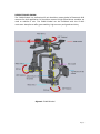
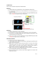
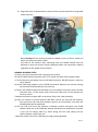
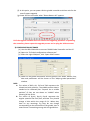
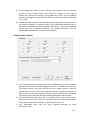
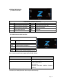
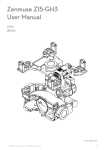
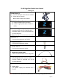
Z1400 High-End Gimbal User Manual Packing list Z1400 Gimbal x 1 a) Includes ZEROUAV motor driver modules b) Video cable of camera Note: shutter cable not included. Z1400 Gimbal Controller x 1 a) Controls Z1400 via Bus Connector b) Include 2 high speed cables: CLOCK & DATA). Attitude Unit (Optional) Provide Attitude data for Z1400 Gimbal Controller when it is not connected to the YS-X4-P Autopilot. Note: Attitude Unit cannot control aircraft. Hot Shoe x 1 For mounting camera to the Z1400. Imperial screw x 2 For mounting camera to gimbal. Screw 4*12 X 1 For mounting camera to gimbal. HDMI video transfer cable Video interface between camera & gimbal PTZ1/PTZ2/PTZ3 dock-connector cable x 3 Connect Z1400 to Attitude Unit or the YS-X4-P Autopilot. Power cable 5.7V power supply for Attitude Unit & Gimbal Note: Pictures are for reference only. Hardware outlook may change without notice. Page | 1 DESCRIPTION OF GIMBAL The Z1400 Gimbal is a professional 3-axis brushless motor gimbal of Panasonic GH3 cameras for AVP application. DC brushless motors & high-speed driver modules are used to stabilize 3 axis. The Z1400 Gimbal can be combined with the YS-X4-P muti-rotor Autopilot to offer great stability, high accuracy and good sensitivity. Digram1: Z1400 Gimbal Page | 2 CONNECTIONS There are two methods to operate the Z1400 Gimbal: METHOD 1 a) Z1400 Gimbal works independently via the Independent Attitude Unit. b) The Independent Attitude Unit’s arrow should point in the same direction as the gimbal head. c) Power to the Attitude Unit must be supplied by the original ZEROTECH power cable. It cannot be supplied directly via 6S battery. Diagram 2 METHOD 2 a) Z1400 is combined with YS-X4-P Autopilot. b) The Attitude Unit not not required. All attitude data is via YS-X4-P Autopilot. c) The arrow on the Z1400 Gimbal and YS-X4-P Autopilot should point in the same direction as the aircraft head. d) Power to the YS-X4-P must be supplied by the original ZEROTECH power cable. It cannot be supplied directly via 6S battery. IMPORTANT MATTERS 1) Follow the connection diagramme strictly. 2) Z1400 Gimbal must be supplied with 6s battery. Anything less than 6S lipo will result in abnormal function. 3) Never power the gimbal without camera attached. The motors will oscillate continuously which can result in a burnt motor and the driver. For longer lifetime function, the camera COG should be balanced (the camera is balanced when released at any angle) before power is supplied. 4) Make sure the arrow of the Z1400 Gimbal and YS-X4-P point in the direction of the aircraft head, otherwise, drifts will appear. 5) Normal PCM RC Receiver cannot be used. Please upgrade to a receiver with PWM-SBUS module. Page | 3 MOUNTING THE CAMERA 1) Install the hot shoe to the camera’s flash slot. 2) Use the factory screws to fix the camera to the top mount on the Z2000 Gimbal, as shown below: Item 1: Top camera mount. Item 2: Screw 2*10 Item 3: Screw 3*6 (Item 2 and 3 have been installed on gimbal) Item 4: Video cable interface 3) Use the factory screws to fix the camera to Z1400 Gimbal. Shown as below: Item 1: Item 2: Item 3: Item 4: Bottom camera mount Screw 4*12 Imperial Screw Screw 3*8 which has been installed on gimbal Page | 4 4) Plug both ends of HDMI cable to camera video output interface to the gimbal video interface: Note: Remove all the camera peripheral hardware (such as filters, hood etc) which can effect the camera COG. The COG of the camera after mounting onto the Z1400 Gimbal must be adjusted so that the camera remains balanced (does not move after release) regardless of the gimbal 3 axis position. NORMAL WORKING STEPS a) Power your RC transmitter after setting up the system. b) Power Z1400 Gimbal Controller with 5.7 V power via ZERO TECH’s power cable. c) The RC Receiver gets power from the Gimbal Controller. DO NOT power it with any other battery. d) Select fixed wing mode on your FUTABA transmitter. Remove any channel mixing. All channels should be Normal (no reverse). e) Power the Z1400 Gimbal with 6S battery via the DuPont connector (with red wire and black wire ) of the Power cable. Ensure the THR stick is at the bottom for security reason. f) Rotate the camera at least 360° at each axis (Pitch, Roll, Yaw) manually. g) Level the camera in normal posture (DO NOT reverse the top and the bottom), then push the THR stick from bottom position to top position, and then the Z1400 Gimbal will be stabilized. h) Pull the THR stick from top position to bottom position whenever the Z1400 Gimbal needs not to be stabilized. Always deactivate the stabilization function if you are not taking video E.g. when taking out the card, taking out the camera battery, video reply, etc. i) Note the motors can burn if working too long with big payload. Page | 5 GIMBAL WORKING MODES a) Programme your CH5 to change the Gimbal tracking modes; Position Top Position Middle Position Bottom Position Working Mode Non-Yaw lock Yaw lock Semi-Yaw lock Function The Gimbal head will NOT follow the movement of the aircraft head. The Gimbal head will follow the aircraft head movement. The Gimbal head will not follow aircraft head if the movement is smaller than 5°. Anything larger than 5o will activate following-operation. b) Programme your CH6 to adjust the movement speed of the Gimbal head. c) Programme CH8 for taking shutter control via a two way switch. OTHER SETTINGS Recording Transmitter middle position – (a) Put THR stick to the bottom position. (b) Move AIL, ELE and RUD sticks to middle position. (c) Move CH5 Switch from top position to bottom quickly 3 times. This will activate the Z1400 to record your Tx neutral point (mid position) for each channel. Resetting Attitude Gyro i) Due to temperature change (e.g. indoor to outdoor), the attitude sensing gyros may drift and resulting in the gimbal moving without stick input. In such case, resetting the gyros is necessary. ii) Move THR stick to the bottom (the gimbal motors deactivate). iii) Carry out CSC (combined switch command) as shown below: OR iv) Keep the sticks at CSC for approx. 30 seconds, before releasing. This will initiate gyro reset. Do not move the camera or gimbal at this time. The reset procedure takes about 3 seconds. v) Check gimbal function after reset by leveling the camera manually, then push the THR stick to the top. The gimbal should now work normally. Page | 6 FIRMWARE UPGRADE 1) ABOUT THE USB-COM CABLE a) Download the USB driver and upgrade software from ZERO TECH official website www.zerouav.com b) Use the USB cable to connect the COM port of the Z1400 Gimbal Controller (white wire on the top) and an USB port of the PC. c) Install the driver according to your computer requirement. 2) FIRMWARE UPGRADE (a) The operation is the same as that of the YS autopilots. (b) DO NOT power ON the Gimbal controller during firmware upgrade. Ensure that your battery is not plugged in. (c) Open the firmware upgrade software. (d) Select COM port for upgrade (if do not know which COM on PC, please click with right mouse “my computer”->“attribute”->device manager”-> “port”(COM/LPT) to have a check). Press“open com” button to enable it, the button“open”will get to black from gray. (e) Click “open” button and select the needed gimbal controller firmware (xxx.arm) in the “open” window. Page | 7 (f) At this point, you can power ON the gimbal controller and then wait for the auto firmware upgrade. (g) Power OFF the controller when “Please Restart AP” appears. PS:If the upgrade software does not execute the upgrading operation on powering the controller, please repeat the upgrade process and re-plug the USB connector. 3) CONFIGURATION SOFTWARE (a) Use the USB-COM cable to connect Z1400 Gimbal Controller and the PC. (b) Open the “Z-Gimbal configuration software.exe”. (c) Select the right COM port, click “Open COM” button (d) Power on the gimbal transmitter and the gimbal. Click “Read” button, then data and parameters will be shown on the “Adjust gimbal parameters” window. DATA A. The values of RUD, AIL, ELE and THR represent the related real stick positions. The middle position data is needed to be collected (See “Capture the a middle position”) if they are not shown as “middle” when releasing all the sticks. B. The values of Gyro1, Gyro2, Gyro3 represent the angular speed of the Pitch, Roll, and Yaw. They should change a little within the range of 0-1. When they have no any meanings, E.g they do not change corresponding to the movement of the gimbal, then it means there is something wrong with the gimbal bus. Page | 8 C. The Encoding Disk values of Pitch , Roll and Yaw represent the real rotation position of each related motor. They should be integers in the range of 0-8191.They should not change if the gimbal keeps static. There should be something wrong with the gimbal bus if they do not change when the gimbal is not static. D. ‘Gimbal Attitude’ represent the attitude of the independent Attitude Unit or the YS-X4-P Autopilot. It should change if the independent Attitude Unit or the YS-X4-P Autopilot are tilted manually. Otherwise, there are something wrong with the connection between the gimbal controller and the independent Attitude Unit or the YS-X4-P autopilot. GIMBAL DEFAULT VALUES A. The original direction the gimbal head can be adjusted by the ‘Error between gimbal head and aircraft head’ drag-down menu. To modify this value, click ‘Test Mode’ button, and push the THR stick to a higher position, then the gimbal head will turn to the new original direction. Click‘Normal Mode’ to return to the normal working state. And then pull the THR stick to the bottom, the motors will be released, and the modified parameters will be saved. B. The PID parameters have been set to a perfect effect, they need not to be adjusted any more. Even if they are modified, they will restore to the default values when the gimbal controller is repowered on next time. C. The ‘Transmitter type’ item can select “gimbal controlled by SBUS transmitter’ only. Page | 9 INTERFACE DEFINITION 1) Gimbal Controller: PTZ1 PTZ2 CONTROLLER Interface Definition Communication Interface 1 CLOCK Clock Interface of Zero Bus Communication Interface 2 DATA Data Interface of Zero Bus PTZ3 Communication Interface 3 S-BUS Receiver Interface COM RS232 COM Interface AI1 Reserved POW Supply to the Gimbal Controller (5.7V) 2) Gimbal Attitude Unit Interface: ATTITUDE UNIT Interface Definition COM PTZ1 PTZ2 PTZ3 S-BUS POW RS232 COM Interface Communication Interface 1 Communication Interface 2 Communication Interface 3 Reserved Supply to the Gimbal Controller (5.7V) List of cameras and lenses supported by Z1400 Gimbal Gimbal model Camera model Lens model support Z1400 Panasonic GH3 Lumix G 14mm f/2.5 Lumix G 20mm/F1.7 LEICA 25/1.4 OLYMPUS M.ZUIKO DIGITAL ED12mm f/2.0 etc. Note: Z2000 Gimbal provides video output interface and camera shutter control interface, but Z1400 provides video output interface only. Page | 10