1
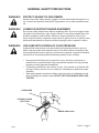
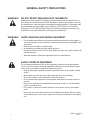
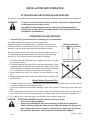
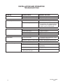
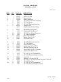
OPERATOR’S AND PARTS MANUAL
SILAGE DEFACER
SERIAL NUMBER: ___________________
MODEL NUMBER: ___________________
800-456-7100 I www.paladinattachments.com
Manual Number: 76807
Part Number: 76807
Rev 2: January 26, 2010
503 Gay Street, Delhi, IA 52223, United States of America Copyright ©
M-1962
10-22-13-3
TABLE OF CONTENTS
PREFACE................................................................................................................................................. 3
SAFETY PRECAUTIONS...................................................................................................................... 4-8
SAFETY STATEMENTS........................................................................................................................................4
GENERAL SAFETY PRECAUTIONS................................................................................................................5-6
EQUIPMENT SAFETY PRECAUTIONS............................................................................................................7-8
INSTALLATION AND OPERATION..................................................................................................... 9-10
ATTACHING AND DETACHING SILAGE DEFACER.............................................................................................9
OPERATING SILAGE DEFACER...........................................................................................................................9
TROUBLESHOOTING ........................................................................................................................................10
MAINTENANCE AND SERVICE........................................................................................................ 11-12
GENERAL INFORMATION.................................................................................................................................... 11
DAILY................................................................................................................................................................... 11
MONTHLY OR EVERY 40 HOURS......................................................................................................................12
CHAIN ADJUSTMENT.........................................................................................................................................12
LUBRICATION......................................................................................................................................................12
DECAL IDENTIFICATION AND REPLACEMENT................................................................................................12
BOLT TORQUE....................................................................................................................................... 13
STORAGE............................................................................................................................................... 14
LIMITED WARRANTY............................................................................................................................ 15
PARTS
SILAGE DEFACER ASSEMBLY #12364......................................................................................................18-21
SILAGE DEFACER ASSEMBLY #12425......................................................................................................22-25
SILAGE DEFACER ASSEMBLY #12686......................................................................................................26-29
SILAGE DEFACER ASSEMBLY #12745......................................................................................................30-33
SILAGE DEFACER ASSEMBLY #12805......................................................................................................34-37
SILAGE DEFACER ASSEMBLY #12871 .....................................................................................................38-41
SILAGE DEFACER ASSEMBLY #12894......................................................................................................42-45
76807
M-1963
4-4-08
1
FOREWORD
Although Bradco has various silage defacers available, we are continually designing new sizes
and mountings. If your combination is not listed, please contact the factory. We have extensive
mounting information available to generate the product you need.
Below is a listing of the silage defacers that are currently available. See the “Parts” section of
this manual for the assemblies “Shown”.
DESCRIPTION & MOUNT
ASSEMBLY #
BOBCAT
Silage Defacer for Telehandler - Bobcat
(Shown) 12894
CATERPILLAR
Silage Defacer for Telehandler, Tractor Loader, or Wheel Loader - CAT IT/TH (Shown)
Silage Defacer for Wheel Loader - CAT IT/TH Only 6 Foot Extension
(Shown)
JCB
Silage Defacer for Telehandler & Tractor Loader - JCB Q-Fit
(Shown)
JOHN DEERE
Silage Defacer for Wheel Loader - John Deere 444H With JRB Coupler
Shown)
Silage Defacer for Wheel Loader - John Deere 244J Only 4 Foot Extension (Shown)
MANITOU
Silage Defacer for Telehandler - Manitou
(Shown)
NEW HOLLAND
Silage Defacer for Telehandler & Tractor Loader - New Holland Q-Fit
(Shown)
2
12425
12805
12364
12745
12871
12686
12364
M-1964
1-26-10-2
76807
PREFACE
GENERAL COMMENTS
Congratulations on the purchase of your new attachment! This product was carefully designed and manufactured to give you many years of dependable service. Only minor maintenance
(such as cleaning and lubricating) is required to keep it in top working condition. Be sure to observe all maintenance procedures and safety precautions in this manual and on any safety decals
located on the product and on any equipment on which the attachment is mounted.
This manual has been designed to help you do a better, safer job. Read this manual carefully and become familiar with its contents.
WARNING! Never let anyone operate this unit without reading the "Safety Precautions"
and "Operating Instructions" sections of this manual.
Always choose hard, level ground to park the vehicle on and set the brake
so the unit cannot roll.
Unless noted otherwise, right and left sides are determined from the operator’s control position when facing the attachment.
NOTE: The illustrations and data used in this manual were current (according to the information available to us) at the time of printing, however, we reserve the right to redesign and
change the attachment as may be necessary without notification.
BEFORE OPERATION
The primary responsibility for safety with this equipment falls to the operator. Make sure the
equipment is operated only by trained individuals that have read and understand this manual. If
there is any portion of this manual or function you do not understand, contact your local authorized
dealer or the manufacturer to obtain further assistance. Keep this manual available for reference.
Provide the manual to any new owners and/or operators.
SAFETY ALERT SYMBOL
This is the “Safety Alert Symbol” used by this industry. This symbol is used to warn
of possible injury. Be sure to read all warnings carefully. They are included for your
safety and for the safety of others working with you.
SERVICE
Use only manufacturer replacement parts. Substitute parts may not meet the required standards.
Record the model and serial number of your unit on the cover of this manual. The parts
department needs this information to insure that you receive the correct parts.
SOUND AND VIBRATION
Sound pressure levels and vibration data for this attachment are influenced by many different parameters: some items are listed below (not inclusive):
• prime mover type, age, condition, with or without cab enclosure and configuration
• operator training, behavior, stress level
• job site organization, working material condition, environment
Based on the uncertainty of the prime mover, operator, and job site, it is not possible to get precise machine and operator sound pressure levels or vibration levels for this attachment.
NOTE: A list of all Paladin Patents can be found at http//www.paladinattachments.com/patents.asp.
M-934
76807
10-22-13-5
3
SAFETY STATEMENTS
THIS SYMBOL BY ITSELF OR WITH A WARNING WORD THROUGHOUT THIS MANUAL IS USED TO CALL YOUR ATTENTION TO INSTRUCTIONS INVOLVING YOUR
PERSONAL SAFETY OR THE SAFETY OF OTHERS. FAILURE TO FOLLOW THESE
INSTRUCTIONS CAN RESULT IN INJURY OR DEATH.
DANGER
THIS SIGNAL WORD IS USED WHERE SERIOUS INJURY OR DEATH
WILL RESULT IF THE INSTRUCTIONS ARE NOT FOLLOWED PROPERLY.
WARNING
THIS SIGNAL WORD IS USED WHERE SERIOUS INJURY OR DEATH
COULD RESULT IF THE INSTRUCTIONS ARE NOT FOLLOWED PROPERLY.
CAUTION
. HIS SIGNAL WORD IS USED WHERE MINOR INJURY COULD RESULT IF
T
THE INSTRUCTIONS ARE NOT FOLLOWED PROPERLY.
NOTICE
NOTICE INDICATES A PROPERTY DAMAGE MESSAGE.
GENERAL SAFETY PRECAUTIONS
WARNING! READ MANUAL PRIOR TO INSTALLATION
Improper installation, operation, or maintenance of this equipment could result in serious injury or death. Operators and maintenance personnel should read this manual,
as well as all manuals related to this equipment and the prime mover thoroughly
before beginning installation, operation, or maintenance. FOLLOW ALL SAFETY
INSTRUCTIONS IN THIS MANUAL AND THE PRIME MOVER’S MANUAL(S).
READ AND UNDERSTAND ALL SAFETY STATEMENTS
Read all safety decals and safety statements in all manuals prior to operating or
working on this equipment. Know and obey all OSHA regulations, local laws, and
other professional guidelines for your operation. Know and follow good work practices when assembling, maintaining, repairing, mounting, removing, or operating this
equipment.
KNOW YOUR EQUIPMENT
Know your equipment’s capabilities, dimensions, and operations before operating.
Visually inspect your equipment before you start, and never operate equipment that
is not in proper working order with all safety devices intact. Check all hardware to
ensure it is tight. Make certain that all locking pins, latches, and connection devices
are properly installed and secured. Remove and replace any damaged, fatigued, or
excessively worn parts. Make certain all safety decals are in place and are legible.
Keep decals clean, and replace them if they become worn or hard to read.
4
M-806
7-28-05-2
76807
GENERAL SAFETY PRECAUTIONS
WARNING! PROTECT AGAINST FLYING DEBRIS
Always wear proper safety glasses, goggles, or a face shield when driving pins in or
out, or when any operation causes dust, flying debris, or any other hazardous material.
WARNING! LOWER OR SUPPORT RAISED EQUIPMENT
Do not work under raised booms without supporting them. Do not use support material made of concrete blocks, logs, buckets, barrels, or any other material that could
suddenly collapse or shift positions. Make sure support material is solid, not decayed, warped, twisted, or tapered. Lower booms to ground level or on blocks. Lower
booms and attachments to the ground before leaving the cab or operator’s station.
WARNING! USE CARE WITH HYDRAULIC FLUID PRESSURE
Hydraulic fluid under pressure can penetrate the skin and cause serious injury or
death. Hydraulic leaks under pressure may not be visible. Before connecting or disconnecting hydraulic hoses, read your prime mover’s operator’s manual for detailed
instructions on connecting and disconnecting hydraulic hoses or fittings.
• Keep unprotected body parts, such as face, eyes, and arms as far away as
possible from a suspected leak. Flesh injected with hydraulic fluid may develop
gangrene or other permanent disabilities.
• If injured by injected fluid, see a doctor at once. If your doctor is not familiar with
this type of injury, ask him or her to research it immediately to determine proper
treatment.
• Wear safety glasses, protective clothing, and use a piece of cardboard or wood
when searching for hydraulic leaks. DO NOT USE YOUR HANDS! SEE ILLUSTRATION.
CARDBOARD
HYDRAULIC HOSE
OR FITTING
MAGNIFYING GLASS
76807
M-807 7-28-05-2
5
GENERAL SAFETY PRECAUTIONS
WARNING! DO NOT MODIFY MACHINE OR ATTACHMENTS
Modifications may weaken the integrity of the attachment and may impair the function, safety, life, and performance of the attachment. When making repairs, use only
the manufacturer’s genuine parts, following authorized instructions. Other parts may
be substandard in fit and quality. Never modify any ROPS (Roll Over Protection
Structure) or FOPS (Falling Object Protective Structure) equipment or device. Any
modifications must be authorized in writing by the manufacturer.
WARNING! SAFELY MAINTAIN AND REPAIR EQUIPMENT
• Do not wear loose clothing or any accessories that can catch in moving parts. If
you have long hair, cover or secure it so that it does not become entangled in the
equipment.
• Work on a level surface in a well-lit area.
• Use properly grounded electrical outlets and tools.
• Use the correct tools for the job at hand. Make sure they are in good condition for
the task required.
• Wear the protective equipment specified by the tool manufacturer.
SAFELY OPERATE EQUIPMENT
Do not operate equipment until you are completely trained by a qualified operator
in how to use the controls, know its capabilities, dimensions, and all safety requirements. See your machine’s manual for these instructions.
• Keep all step plates, grab bars, pedals, and controls free of dirt, grease, debris,
and oil.
• Never allow anyone to be around the equipment when it is operating.
• Do not allow riders on the attachment or the prime mover.
• Do not operate the equipment from anywhere other than the correct operator’s
position.
• Never leave equipment unattended with the engine running, or with this attachment in a raised position.
• Do not alter or remove any safety feature from the prime mover or this attachment.
• Know your work site safety rules as well as traffic rules and flow. When in doubt
on any safety issue, contact your supervisor or safety coordinator for an explanation.
6
M-808 7-28-05-2
76807
EQUIPMENT SAFETY PRECAUTIONS
WARNING! KNOW WHERE UTILITIES ARE
Observe overhead electrical and other utility lines. Be sure equipment will clear them.
When digging, call your local utilities for location of buried utility lines, gas, water, and
sewer, as well as any other hazard you may encounter.
OPERATING THE SILAGE DEFACER
•
•
•
Clear the work area of all bystanders before operation!
Operate only from the operator’s station with seatbelt properly attached.
Do not exceed the lifting capacity of your prime mover and attachment. Always
observe lift capacity limits listed in machine specifications or on load charts furnished with the prime mover.
• Reduce speed when driving over rough terrain, on a slope, or turning, to avoid
overturning the vehicle.
• Never use the attachment for a work platform or personnel carrier.
• An operator must not use drugs or alcohol, which can change his or her alertness
or coordination. An operator taking prescription or over-the-counter drugs should
seek medical advice on whether or not he or she can safely operate equipment.
• Always check locking pins before operating any attachment.
• Before exiting the prime mover, lower the attachment to the ground, apply the
brakes, turn off the prime mover’s engine, and remove the key.
TRANSPORTING THE SILAGE DEFACER
•
•
•
•
•
Travel only with the attachment in a safe transport position to prevent
uncontrolled movement. Drive slowly over rough ground, and on slopes.
Allow for the added length of the silage defacer when transporting, so as not to
catch the unit on obstables.
When driving on public roads, use safety lights, reflectors, Slow Moving Vehicle
signs, etc. to prevent accidents. Check local government regulations that may
affect you.
Do not drive close to ditches, excavations, etc., as a cave-in could result.
Do not smoke when refueling the prime mover. Allow room in the gas tank for
expansion. Wipe up any spilled fuel, and secure cap tightly, when done.
MAINTAINING THE SILAGE DEFACER
•
•
•
•
•
76807
Before performing maintenance, lower the attachment to the ground, apply the
brakes, turn off the engine, and remove the key.
Never perform any work on the equipment unless you are authorized and qualified to do so. Always read the operator’s and service manual(s) before
any repair is made. After completing maintenance or repair, check for correct
functioning of the attachment. If not functioning properly, always attach a “DO
NOT OPERATE” tag to the machine until all problems are corrected.
Worn, damaged, or illegible safety decals must be replaced. New safety decals
can be ordered from the manufacturer.
Never make hydraulic repairs while the system is under pressure. Serious personal injury or death could result.
Never work under a raised attachment.
M-1976 4-3-08
7
THIS PAGE
IS INTENTIONALLY
BLANK
8
76807
INSTALLATION AND OPERATION
ATTACHING AND DETACHING SILAGE DEFACER
Please see your vehicle operator’s manual for instructions on attaching and detaching your equipment.
WARNING!
To prevent serious personal injury or death, only attach equipment that
is designed for your prime mover.
Specified lift capacities must not be exceeded, otherwise machine
stability will not be sufficient. Always observe lift capacity limits listed
in machine specifications.
OPERATING SILAGE DEFACER
•
Read all Safety Precautions before operating your new attachment.
The silage defacer was designed to loosen haylage and
silage from a tightly compacted bunker. It maintains a smooth, compacted bunker-face for reduced spoil, and the open design allows the
operator to see the bunker face and the surrounding work area.
PROPER OPERATION
(1”-3” MATERIAL PER PASS)
There are guides on the end of each arm to limit the depth of each cut.
The guides can be easily adjusted by loosening the bolts and sliding
the guide in or out until the desired cutting depth is reached.
1. Clear the area of all bystanders, and engage the defacer only from
the operator’s station.
2. Position the defacer at the top of the bunker and engage the auxiliary
hydraulics. When the defacer has reached full speed, slowly lower
into the silage at the desired cutting depth. Do not deface more than
1”-3” of material on each pass, depending on the material.
3. Keep defacer level while it is lowering, to help maintain an even
cut.
4. Repeat steps #1 through #3 until the desired amount of silage has
been obtained.
IMPROPER OPERATION
Silage Defacer Operating Tips
1. For best results do not force the defacer down through the material, but allow gravity and the removal
of material to determine the downward speed.
2. To prevent attachment and property damage, avoid direct contact of tines with bunker walls and
floor.
3. Due to silage piling up on the ground, to obtain a clean cut of the entire bunker face, you may wish to
first cut the bottom 4 feet, and then reposition the defacer at the top, and finish the downward cut.
4. A 2” depth of cut is recommended to avoid stalling, and to obtain a clean face.
DANGER!
76807
ROTATING HAZARD! To prevent serious injury or death:
• Clear area of all bystanders.
• Operate the attachment only when properly seated at the operator’s
station. Before exiting the prime mover, lower the defacer to the ground,
turn off the prime mover’s engine, remove the key and apply the brakes.
• Do not leave operator’s station until all movement has stopped.
M-1965 4-4-08
9
INSTALLATION AND OPERATION
TROUBLESHOOTING
PROBLEM
POSSIBLE CAUSE
POSSIBLE SOLUTION
Excessive noise.
1. Bearings worn and “squeaking”.
• Check and replace, as necessary.
2. Cutters bent.
• Repair or replace.
1. Chain loose.
• See “Troubleshooting Loose Chain”.
2. Cutters damaged.
• Check blades and repair or replace,
as necessary. See “Operating Silage
Defacer” in the “Installation and Operation” section of this manual.
1. Chain broken.
• Repair or replace.
2. Drive motor failure.
• Repair or replace.
3. Drive motor key broken.
• Replace key.
4. Sprocket damaged.
• Replace sprocket.
1. Cam lock not tight.
• Re-tension chain, and tighten mounting bolts on cam lock.
2. Sprocket, bearing, or chain worn.
• Check, and replace any worn parts.
1. Hydraulic oil level too low.
• Refer to skid-steer's owners manual.
2. Obstruction in hydraulic lines.
• Remove obstruction and replace, if
necessary.
3. Couplers not engaged correctly.
• Engage couplers.
4. Hydraulic system overloaded,
and system relief open.
• Reduce load.
Decreased performance.
Cutters not turning.
Loose Chain.
Excessive oil temperature.
10
M-1966 4-4-08
76807
MAINTENANCE & SERVICE
GENERAL INFORMATION
Regular maintenance is the key to long equipment life and safe operation. Maintenance
requirements have been kept to an absolute minimum. However, it is very important that these
maintenance functions be performed as described in this section.
WARNING!
DO NOT OPERATE THE SILAGE DEFACER DURING ANY MAINTENANCE, OR WHILE THE TOP CHAIN COVER IS
REMOVED.
DAILY
•
•
•
•
Check all bolts and nuts for tightness.
Replace any missing bolts or nuts with approved replacement parts.
Check hydraulic system for hydraulic oil leaks. See procedure below.
Visually inspect the machine for worn parts or cracked welds, and repair, as necessary.
WARNING! Escaping fluid under pressure can have sufficient force to penetrate the
skin, causing serious personal injury. Fluid escaping from a very small
hole can be almost invisible. Use a piece of cardboard or wood, rather than
hands to search for suspected leaks. Keep unprotected body parts, such as face, eyes, and arms as far away as
possible from a suspected leak. Flesh injected with hydraulic fluid may
develop gangrene or other permanent disabilities.
If injured by injected fluid, see a doctor at once. If your doctor is not familiar with this type of injury, ask him or her to research it immediately to
determine proper treatment.
CARDBOARD
HYDRAULIC HOSE
OR FITTING
MAGNIFYING GLASS
IMPORTANT: When replacing parts, use only factory approved replacement parts. Manufacturer will not claim responsibility for use of unapproved parts or accessories and/or other damages as a result of their use.
76807
M-1967
4-4-08
11
MAINTENANCE & SERVICE
•
•
•
•
MONTHLY OR EVERY 40 HOURS OF OPERATION
Check all bearings for tightness. Tighten or replace, as needed.
Clean equipment of dirt, oil, grease, etc. This will assist you in making a visual inspection, and help
avoid overlooking worn or damaged components.
Adjust the shoe weldments on the silage defacer so material is removed, but the shoe is never less
than 1/2” shorter than the blades.
Adjust and lubricate the drive chain. (See “Chain Adjustment” below.) To lubricate the drive chain:
Remove the top chain cover and spray a chain lubricant along the top of the upper and lower portion
of the drive chain.
CHAIN ADJUSTMENT
We recommend adjusting the chain on all of the silage defacers after the initial 4 hours, and then
monthly thereafter.
To Adjust the Chain: Remove the top chain cover and loosen the two bolts on the motor mounting
plate, and the one bolt on the cam lock. Insert a 1/2” ratchet into the cam lock, and rotate until the chain
is tight. A properly adjusted chain will have a minimal amount of chain deflection. Over-tensioning will
cause premature wear.
NOTE: If all of the cam lock adjustment is used and the chain and sprocket are still
serviceable, you can remove a “half link” from the chain at the master link location.
LUBRICATION
The only other lubrication your attachment needs is the greasing of the flangette and bearing set. A
grease fitting has been installed to facilitate this task. We recommended that all grease fittings be lubricated after the intitial 8 hours of operation, and then after every 40 hours of use thereafter.
DECAL IDENTIFICATION AND REPLACEMENT
Decal placement and identification for all of the attachments can be found on the parts diagrams and
lists located at the back of this manual. The decals are identified by their part numbers with reductions
of the actual decals located on the page. Use this information to order replacements for missing, illegible or damaged deals. When replacing parts with safety signs attached, the safety sign must also be
replaced. All Safety Decals are free of charge. Contact your dealer for replacements.
REPLACING SAFETY SIGNS:
1.
2.
3.
4.
Clean the area of application with nonflammable solvent.
Wash the same area with soap and water, and then allow the surface to fully dry.
Remove the backing from the safety sign, exposing the adhesive surface.
Apply the safety sign to the location shown in the parts diagram, and smooth out bubbles.
Helpful Hints:
1. Decals adhere to a warm surface better than a cold surface.
2. Applying heat (from a hair dryer) will greatly improve your ability to remove a damaged decal before
preparing the surface for installation of a new one.
M-1968
12
4-4-08
76807
BOLT TORQUE SPECIFICATIONS
GENERAL TORQUE SPECIFICATION TABLES
Use the following charts when determining bolt torque specifications when special torques are not given.
Always use grade 5 or better when replacing bolts.
SAE BOLT TORQUE SPECIFICATIONS
NOTE: The following torque values are for use with extreme pressure lubricants, plating or hard washer
applications Increase torque 15% when using hardware that is unplated and either dry or lubricated with
engine oil.
SAE GRADE 5 TORQUE
Bolt Size
Pounds Feet
Newton-Meters
SAE GRADE 8 TORQUE
Pounds Feet
UNC
Newton-Meters
Inches
Millimeters
UNC
UNF
UNC
UNF
UNF
UNC
UNF
1/4
5/16
6.35
7.94
8
14
9
17
11
19
12
23
10
20
13
25
14
27
18
34
62
3/8
9.53
30
36
41
49
38
46
52
7/16
11.11
46
54
62
73
60
71
81
96
1/2
12.70
68
82
92
111
94
112
127
152
9/16
14.29
94
112
127
136
163
184
221
5/8
15.88
128
153
174
152
207
187
224
254
304
3/4
19.05
230
275
312
373
323
395
438
536
7/8
22.23
340
408
461
553
510
612
691
830
1
25.40
493
592
668
803
765
918
1037
1245
1-1/8
25.58
680
748
922
1014
1088
1224
1475
1660
1-1/4
31.75
952
1054
1291
1429
1547
1700
2097
2305
1-3/8
34.93
1241
1428
1683
1936
2023
2312
2743
3135
1-1/2
38.10
1649
1870
2236
2535
2686
3026
3642
4103
Bolt head identification marks as per
grade. NOTE: Manufacturing Marks Will
Vary
METRIC BOLT TORQUE SPECIFICATIONS
Bolt head identification marks as per grade.
NOTE: The following torque values are for use with metric
hardware that is unplated and either dry or lubricated with
engine oil. Reduce torque 15% when using hardware that has
extreme pressure lubricants, plating or hard washer
applications.
Size of Bolt
Grade No.
Pitch (mm)
Pounds Feet
Newton-Meters
Pitch (mm)
Pounds Feet
Newton-Meters
M6
5.6
8.8
10.9
1.0
3.6-5.8
5.8-.4
7.2-10
4.9-7.9
7.9-12.7
9.8-13.6
-
-
-
M8
5.6
8.8
10.9
1.25
7.2-14
17-22
20-26
9.8-19
23-29.8
27.1-35.2
1.0
12-17
19-27
22-31
16.3-23
25.7-36.6
29.8-42
M10
5.6
8.8
10.9
1.5
20-25
34-40
38-46
27.1-33.9
46.1-54.2
51.5-62.3
1.25
20-29
35-47
40-52
27.1-39.3
47.4-63.7
54.2-70.5
M12
5.6
8.8
10.9
1.75
28-34
51-59
57-66
37.9-46.1
69.1-79.9
77.2-89.4
1.25
31-41
56-68
62-75
42-55.6
75.9-92.1
84-101.6
M14
5.6
8.8
10.9
2.0
49-56
81-93
96-109
66.4-75.9
109.8-126
130.1-147.7
1.5
52-64
90-106
107-124
70.5-86.7
122-143.6
145-168
M16
5.6
8.8
10.9
2.0
67-77
116-130
129-145
90.8-104.3
157.2-176.2
174.8-196.5
1.5
69-83
120-138
140-158
93.5-112.5
162.6-187
189.7-214.1
M18
5.6
8.8
10.9
2.0
88-100
150-168
175-194
119.2-136
203.3-227.6
237.1-262.9
1.5
100-117
177-199
202-231
136-158.5
239.8-269.6
273.7-313
M20
5.6
8.8
10.9
2.5
108-130
186-205
213-249
146.3-176.2
252-277.8
288.6-337.4
1.5
132-150
206-242
246-289
178.9-203.3
279.1-327.9
333.3-391.6
76807
10360
3-20-08-3
13
STORAGE
GENERAL INFORMATION
The following storage procedure will help you to keep your attachment in top condition. It will
also help you get off to a good start the next time your equipment is needed. We therefore
strongly recommend that you take the extra time to follow these procedures whenever your
attachment will not be used for an extended period of time.
PREPARATION FOR STORAGE
1.
Clean the attachment thoroughly, removing all mud, dirt, and grease.
2.
Inspect for visible signs of wear, breakage, or damage. Order any parts required, and
make the necessary repairs, to avoid delays when starting next season.
3.
Tighten all loose nuts, capscrews, and hydraulic connections.
4.
Lubricate all grease fittings.
5.
Connect the hydraulic couplers together, or install covers, to protect the hydraulic system from contaminates.
6.
Touch up all unpainted and exposed areas with paint, to prevent rust.
7.
Replace decals, if damaged or in unreadable condition.
8.
Store the attachment in a dry and protected place, with a cover, if possible. Leaving the
attachment outside will materially shorten its life.
REMOVING FROM STORAGE
1.
Remove all protective coverings.
2.
Check hydraulic hoses for deterioration, and replace if necessary.
14
M-1969
3-5-08
76807
Limited Warranty
Except for the Excluded Products as described below, all new products are warranted to be free from defects
in material and/or workmanship during the Warranty Period, in accordance with and subject to the terms and
conditions of this Limited Warranty.
1.
Excluded Products. The following products are excluded from this Limited Warranty:
(a) Any cable, part that engages with the ground (i.e. sprockets), digging chain, bearing, teeth, tamping
and/or demolition head, blade cutting edge, pilot bit, auger teeth and broom brush that either constitutes or is part
of a product.
(b) Any product, merchandise or component that, in the opinion of Paladin Light Construction1, has been
(i) misused; (ii) modified in any unauthorized manner; (iii) altered; (iv) damaged; (v) involved in an accident; or (vi)
repaired using parts not obtained through Paladin Light Construction.
2.
Warranty Period. The Limited Warranty is provided only to those defects that occur during the Warranty
Period, which is the period that begins on the first to occur of: (i) the date of initial purchase by an end-user, (ii) the
date the product is first leased or rented, or (iii) the date that is six (6) months after the date of shipment by Paladin
Light Construction as evidenced by the invoiced shipment date (the “Commencement Date”) and ends on the date
that is twelve (12) months after the Commencement Date.
3.
Terms and Conditions of Limited Warranty. The following terms and conditions apply to the Limited Warranty
hereby provided:
(a)
the product.
Option to Repair or Replace. Paladin Light Construction shall have the option to repair or replace
(b)
Timely Repair and Notice. In order to obtain the Limited Warranty, (i) the product must be repaired
within thirty (30) days from the date of failure, and (ii) a claim under the warranty must be submitted to Paladin Light
Construction in writing within thirty (30) days from the date of repair.
(c)
Return of Defective Part or Product. If requested by Paladin Light Construction, the alleged
defective part or product shall be shipped to Paladin Light Construction at its manufacturing facility or other location
specified by Paladin Light Construction, with freight PRE-PAID by the claimant, to allow Paladin Light Construction
to inspect the part or product.
Claims that fail to comply with any of the above terms and conditions shall be denied.
LIMITATIONS AND EXCLUSIONS.
THIS LIMITED WARRANTY IS IN LIEU OF ALL OTHER WARRANTIES, EXPRESS OR IMPLIED, INCLUDING
WITHOUT LIMITATION THE WARRANTIES OF MERCHANTABILITY, FITNESS FOR A PARTICULAR PURPOSE
AND ANY WARRANTY BASED ON A COURSE OF DEALING OR USAGE OF TRADE.
IN NO EVENT SHALL PALADIN LIGHT CONSTRUCTION BE LIABLE FOR CONSEQUENTIAL OR SPECIAL
DAMAGES.
IN NO EVENT SHALL PALADIN LIGHT CONSTRUCTION BE LIABLE FOR ANY LOSS OR CLAIM IN AN
AMOUNT IN EXCESS OF THE PURCHASE PRICE, OR, AT THE OPTION OF PALADIN LIGHT CONSTRUCTION,
THE REPAIR OR REPLACEMENT, OF THE PARTICULAR PRODUCT ON WHICH ANY CLAIM OF LOSS OR
DAMAGE IS BASED. THIS LIMITATION OF LIABILITY APPLIES IRRESPECTIVE OF WHETHER THE CLAIM
IS BASED ON BREACH OF CONTRACT, BREACH OF WARRANTY, NEGLIGENCE OR OTHER CAUSE AND
WHETHER THE ALLEGED DEFECT IS DISCOVERABLE OR LATENT.
Attachment Technologies Inc., a subsidiary of Paladin Brands Holding, Inc. (PBHI) is referred to herein as Paladin Light
Construction.
February 10, 2010
1
76807
15
THIS PAGE
IS INTENTIONALLY
BLANK
16
76807
PARTS
The following section contains detailed diagrams and parts lists which include your
attachment. Please use these diagrams and parts lists to locate replacement parts, prior to
contacting the parts department.
When servicing your attachment, remember to use only original manufacturer replacement parts. Substitute parts may not meet the standards required for safe, dependable operation.
To facilitate parts ordering, have the model and serial number of your product ready, to
ensure that you receive the correct parts for your specific attachment.
The model and serial number for your attachment should be recorded in the space
provided on the cover of this manual. This information may be obtained from the serial number
identification plate located on your attachment. See the parts diagram for your attachment
for the location.
NOTE: Most daily and emergency orders received by 2:00 P.M. will be shipped the same
day received, with “Emergency-Machine-Down” orders receiving first priority.
PARTS DEPARTMENT
(734) 996-9116
(800) 456-7100
We Encourage Fax Orders
(734) 996-9014
76807
M-1127
1-26-10-3
17
SILAGE DEFACER
ASSEMBLY #12364
DIAGRAM 1 OF 2
28
29
29
11
30
10
1
4
28
28
5
7
29
13
6
11
12
26
27
24
29
28
8
23
21 18
6
4
15
5
13
9
23
25
7
3
8
22
7
17
19
20
16
14
2
M-1938
18
2-25-08
76807
SILAGE DEFACER
ASSEMBLY #12364
LIST 1 OF 2
ITEM
QTY.
PART NO.
DESCRIPTION
1
1
105447
Blade, Left End
2
1
105448
Blade, Center
3
1
105449
Blade, Right End
4
2
1051
.38” UNC x 3.00” Hex Capscrew
2
1525
.38” Flat Washer
2
1837
.38” UNC Deformed Lock Nut
5
2
89129
Flangette Set
-
6616
Replacement Grease Fitting
6 289127 Ball Bearing With Collar
-
1624
Replacement Set Screw
7
12
1088
.50” UNC x 1.00 Hex Capscrew
12
1646
.50” Hard Flat Washer
8
2
33427
Shoe (Depth Guide)
9 115751 Bottom Chain Cover
10 132849 Top Chain Cover
11
4
1837
.38” UNC Deformed Lock Nut
4
1514
.38” Flat Washer
12
1
15249
Silage Defacer Frame
13
3
105482
Square Key, .38” x 1.75”
14
1
32905
Sprocket, 18 Tooth, No. 80
15 132906 Drive Chain, No. 80, 73 Pitches
-
53298
Replacement Master Link
16 11872 .50” UNC X 1.50” Carriage Bolt
1
1790
.50” UNC Serrated Flange Lock Nut
17
1
32848
Cam Lock
18
1
33249
Sprocket, 10 Tooth, No. 80
19
4
22336
.50” UNC x 1.50” Socket Head Capscrew, Grade 8
4
1228
.50” UNC Hex Nut
20 21872 .50” UNC X 1.50” Carriage Bolt
2
1790
.50” UNC Serrated Flange Lock Nut
M-1939
76807
2-25-08
19
SILAGE DEFACER
ASSEMBLY #12364
DIAGRAM 2 OF 2
28
29
29
11
30
10
1
4
28
28
5
7
29
13
6
11
12
26
27
24
29
28
8
23
21 18
6
4
15
5
13
9
23
25
7
3
8
22
7
17
19
20
16
14
2
20
M-1940
2-25-08
76807
SILAGE DEFACER
ASSEMBLY #12364
LIST 2 OF 2
ITEM QTY. PART NO.
DESCRIPTION
21
1
32847
Motor Mounting Plate
22133200Motor
-
5662
Replacement Key
23
2
37975
Hose .62” x 60” 8MBo-10MBo
24
1
32548
Female Coupler Cover
25
1
84928
Female Quick Coupler
26
1
32549
Male Coupler Cover
27
1
84923
Male Quick Coupler
28
3
4105
Danger Stand Clear Decal
29
3
4235
Moving Paddles Danger Decal
30
1
-----
Serial Number Identification Tag Location
76807
M-1941
3-31-08
21
SILAGE DEFACER
ASSEMBLY #12425
DIAGRAM 1 OF 2
25
26
11
26
10
27
1
29 24
23
4
25
5
7
28
30
30
29
13
6
8
11
12
25
9
26
7
26
8
25
21 18
6
4
15
3
5
13
22
7
17
19
20
16
14
2
M-1946
22
1-26-10-2
76807
SILAGE DEFACER
ASSEMBLY #12425
ITEM
LIST 1 OF 2
QTY.
PART NO.
1
1
1
2
2
2
2
-
105447
105448
105449
1051
1525
1837
89129
6616
Blade, Left End
Blade, Center
Blade, Right End
.38” UNC x 3.00” Hex Capscrew
.38” Flat Washer
.38” UNC Deformed Lock Nut
Flangette Set
Replacement Grease Fitting
62
-
7
12
12
8
2
91
101
89127
1624
1088
1646
33427
15751
32849
Ball Bearing With Collar
Replacement Set Screw
.50” UNC x 1.00 Hex Capscrew
.50” Hard Flat Washer
Shoe (Depth Guide)
Bottom Chain Cover
Top Chain Cover
11
4
4
12
1
13
3
14
1
151
-
1837
1514
16794
105482
32905
32906
53298
.38” UNC Deformed Lock Nut
.38” Flat Washer
Silage Defacer Frame
Square Key, .38” x 1.75”
Sprocket, 18 Tooth, No. 80
Drive Chain, No. 80, 73 Pitches
Replacement Master Link
161
1
17
1
18
1
19
4
4
202
2
1872
1790
32848
33249
22336
1228
1872
1790
.50” UNC X 1.50” Carriage Bolt
.50” UNC Serrated Flange Lock Nut
Cam Lock
Sprocket, 10 Tooth, No. 80
.50” UNC x 1.50” Socket Head Capscrew, Grade 8
.50” UNC Hex Nut
.50” UNC X 1.50” Carriage Bolt
.50” UNC Serrated Flange Lock Nut
21
1
221
-
23
1
24
1
25
3
32847
33200
5662
Varies
4338
4105
Motor Mounting Plate
Motor
Replacement Key
Logo
Made in USA Decal
Danger Stand Clear Decal
26
27
28
29
30
4235Moving Paddles Danger Decal
-----Serial Number Identification Tag Location
1028
.31” UNC x 2.50” Hex Capscrew
1502.31” Lock Washer
1513
.31” Flat Washer
14228 Stop Block
10012 .75” UNC x 2.25” Hex Capscrew, Grade 8
1507
.75” Lock Washer
1
2
3
4
5
3
1
2
2
2
2
4
4
DESCRIPTION
M-1947
76807
1-26-10-2
23
SILAGE DEFACER
ASSEMBLY #12425
DIAGRAM 2 OF 2
31
32
33
33
34
34
35
37
38
36
35
Flow Control Valve
40
39
41
41
Motor
24
M-1948
4-3-08
76807
SILAGE DEFACER
ASSEMBLY #12425
ITEM
QTY.
PART NO.
LIST 2 OF 2
DESCRIPTION
31
32
33
34
35
1
1
2
2
2
22518
22519
3419
37513
3409
Female Quick Coupler
Male Quick Coupler
Straight Connector, 12MBo-12MJ
Hose .75” x 60” 12FJX-12FJX
Straight Connector, 16MBo-12MJ
36
37
38
39
40
1
1
1
1
1
25314
30350
30292
3
7658
22571
Flow Control Valve
Tee
Straight Connector, 16MBo-12FBo
Hose .75” x 42” 12FJX-12FJX90°
Hose .75” x 34” 12FJX-12FJX
41
2
3286 Straight Connector, 10MBo-12MJ
76807
M-1949
4-3-08
25
SILAGE DEFACER
ASSEMBLY #12686
DIAGRAM 1 OF 2
28
29
29
11
10
30
1
27
28
4
7
5
26
13
6
12
25
28
8
11
24
29
9
25
7
29
23
28
4
23
24
8
21
6
18
15
3
5
13
7
22
17
16
19
20
14
2
M-1942
26
1-26-10-2
76807
SILAGE DEFACER
ASSEMBLY #12686
LIST 1 OF 2
ITEM
QTY.
PART NO.
DESCRIPTION
1
1
105447
Blade, Left End
2
1
105448
Blade, Center
3
1
105449
Blade, Right End
4
2
1051
.38” UNC x 3.00” Hex Capscrew
2
1525
.38” Flat Washer
2
1837
.38” UNC Deformed Lock Nut
5
2
89129
Flangette Set
-
6616
Replacement Grease Fitting
6 289127 Ball Bearing With Collar
-
1624
Replacement Set Screw
7
12
1088
.50” UNC x 1.00 Hex Capscrew
12
1646
.50” Hard Flat Washer
8
2
33427
Shoe (Depth Guide)
9 115751 Bottom Chain Cover
10 132849 Top Chain Cover
11
4
1837
.38” UNC Deformed Lock Nut
4
1514
.38” Flat Washer
12
1
100341
Silage Defacer Frame
13
3
105482
Square Key, .38” x 1.75”
14
1
32905
Sprocket, 18 Tooth, No. 80
15 132906 Drive Chain, No. 80, 73 Pitches
-
53298
Replacement Master Link
1611872 .50” UNC X 1.50” Carriage Bolt
1
1790
.50” UNC Serrated Flange Lock Nut
17
1
32848
Cam Lock
18
1
33249
Sprocket, 10 Tooth, No. 80
19
4
22336
.50” UNC x 1.50” Socket Head Capscrew, Grade 8
4
1228
.50” UNC Hex Nut
2021872 .50” UNC X 1.50” Carriage Bolt
2
1790
.50” UNC Serrated Flange Lock Nut
M-1943
76807
4-10-08
27
SILAGE DEFACER
ASSEMBLY #12686
DIAGRAM 2 OF 2
28
29
29
11
10
30
1
27
28
4
7
5
26
13
6
12
25
28
8
11
24
29
9
25
7
29
23
28
4
23
24
8
21
6
18
15
3
5
13
7
22
17
16
19
20
14
2
28
M-1944
1-26-10-2
76807
SILAGE DEFACER
ASSEMBLY #12686
LIST 2 OF 2
ITEM
QTY. PART NO.
DESCRIPTION
21
1
32847
Motor Mounting Plate
22 133200 Motor
-
5662
Replacement Key
23
2
38187
Hose .62” x 80” 8MBo-10MBo
24
2
84928
Female Quick Coupler
25
2
32548
Female Coupler Cover
26 1Varies Logo
27
1
4338
Made in USA Decal
28
3
4105
Danger Stand Clear Decal
29
3
4235
Moving Paddles Danger Decal
30
1
-----
Serial Number Identification Tag Location
76807
M-1945
1-26-10-2
29
SILAGE DEFACER
ASSEMBLY #12745
DIAGRAM 1 OF 2
25
26
26
11
10
27
23
1
24
4
25
28
7
5
13
6
12
8
11
25
9
26
7
26
8
25
6
4
21 18
3
15
5
13
7
22
17
16
19
20
14
2
30
M-1954
1-26-10-2
76807
SILAGE DEFACER
ASSEMBLY #12745
ITEM
LIST 1 OF 2
QTY.
PART NO.
1
1
1
2
2
2
2
-
105447
105448
105449
1051
1525
1837
89129
6616
Blade, Left End
Blade, Center
Blade, Right End
.38” UNC x 3.00” Hex Capscrew
.38” Flat Washer
.38” UNC Deformed Lock Nut
Flangette Set
Replacement Grease Fitting
62
-
7
12
12
8
2
91
101
89127
1624
1088
1646
33427
15751
32849
Ball Bearing With Collar
Replacement Set Screw
.50” UNC x 1.00 Hex Capscrew
.50” Hard Flat Washer
Shoe (Depth Guide)
Bottom Chain Cover
Top Chain Cover
11
4
4
12
1
13
3
14
1
151
-
1837
1514
102902
105482
32905
32906
53298
.38” UNC Deformed Lock Nut
.38” Flat Washer
Silage Defacer Frame
Square Key, .38” x 1.75”
Sprocket, 18 Tooth, No. 80
Drive Chain, No. 80, 73 Pitches
Replacement Master Link
161
1
17
1
18
1
19
4
4
202
2
1872
1790
32848
33249
22336
1228
1872
1790
.50” UNC X 1.50” Carriage Bolt
.50” UNC Serrated Flange Lock Nut
Cam Lock
Sprocket, 10 Tooth, No. 80
.50” UNC x 1.50” Socket Head Capscrew, Grade 8
.50” UNC Hex Nut
.50” UNC X 1.50” Carriage Bolt
.50” UNC Serrated Flange Lock Nut
21
1
221
-
23
1
24
1
25
3
32847
33200
5662
Varies
4338
4105
Motor Mounting Plate
Motor
Replacement Key
Logo
Made in USA Decal
Danger Stand Clear Decal
26
27
28
4235Moving Paddles Danger Decal
-----Serial Number Identification Tag Location
1028
.31” UNC x 2.50” Hex Capscrew
1502.31” Lock Washer
1513
.31” Flat Washer
1
2
3
4
5
3
1
2
2
2
DESCRIPTION
M-1955
76807
1-26-10-2
31
SILAGE DEFACER
ASSEMBLY #12745
DIAGRAM 2 OF 2
29
29
30
30
33
31
34
32
31
Flow Control Valve
36
35
37
37
Motor
32
M-1956
3-3-08
76807
SILAGE DEFACER
ASSEMBLY #12745
ITEM
QTY.
PART NO.
DESCRIPTION
3419
37513
Straight Connector, 12MBo-12MJ
Hose .75” x 60” 12FJX-12FJX
29
30
2
2
31
32
33
34
35
2
3409
125314
130350
1
30292
1
37658
LIST 2 OF 2
Straight Connector, 16MBo-12MJ
Flow Control Valve
Tee
Straight Connector, 16MBo-12FBo
Hose .75” x 42” 12FJX-12FJX90°
36 122571 Hose .75” x 34” 12FJX-12FJX
37
2
3286 Straight Connector, 10MBo-12MJ
M-1957
76807
3-3-08
33
SILAGE DEFACER
ASSEMBLY #12805
DIAGRAM 1 OF 2
25
26
29
23
11
1
10
31
4
27
30
29
26
28
30
24
5
25
7
13
6
12
11
25
26
9
7
26
21 18
8
25
4
15
6
3
22
5
13
8
17
16
19
20
14
7
2
M-1950
34
1-26-10-2
76807
SILAGE DEFACER
ASSEMBLY #12805
ITEM
QTY.
1
2
3
4
5
1
1
1
2
2
2
2
-
PART NO.
LIST 1 OF 2
DESCRIPTION
105447
105448
105449
1051
1525
1837
89129
6616
Blade, Left End
Blade, Center
Blade, Right End
.38” UNC x 3.00” Hex Capscrew
.38” Flat Washer
.38” UNC Deformed Lock Nut
Flangette Set
Replacement Grease Fitting
62
-
7
12
12
8
2
91
101
89127
1624
1088
1646
33427
15751
32849
Ball Bearing With Collar
Replacement Set Screw
.50” UNC x 1.00 Hex Capscrew
.50” Hard Flat Washer
Shoe (Depth Guide)
Bottom Chain Cover
Top Chain Cover
11
4
4
12
1
13
3
14
1
151
-
1837
1514
104775
105482
32905
32906
53298
.38” UNC Deformed Lock Nut
.38” Flat Washer
Silage Defacer Frame
Square Key, .38” x 1.75”
Sprocket, 18 Tooth, No. 80
Drive Chain, No. 80, 73 Pitches
Replacement Master Link
161
1
17
1
18
1
19
4
4
202
2
1872
1790
32848
33249
22336
1228
1872
1790
.50” UNC X 1.50” Carriage Bolt
.50” UNC Serrated Flange Lock Nut
Cam Lock
Sprocket, 10 Tooth, No. 80
.50” UNC x 1.50” Socket Head Capscrew, Grade 8
.50” UNC Hex Nut
.50” UNC X 1.50” Carriage Bolt
.50” UNC Serrated Flange Lock Nut
21
1
221
-
23
1
24
1
25
3
32847
33200
5662
Varies
4338
4105
Motor Mounting Plate
Motor
Replacement Key
Logo
Made in USA Decal
Danger Stand Clear Decal
26
27
28
29
30
3
1
2
2
2
2
4
4
4235Moving Paddles Danger Decal
-----Serial Number Identification Tag Location
1028
.31” UNC x 2.50” Hex Capscrew
1502.31” Lock Washer
1513
.31” Flat Washer
14228 Stop Block
10012 .75” UNC x 2.25” Hex Capscrew, Grade 8
1507
.75” Lock Washer
31
1
17143
76807
Double Hose Clamp
M-1951
1-26-10-2
35
SILAGE DEFACER
ASSEMBLY #12805
DIAGRAM 2 OF 2
33
32
34
34
35
35
36
38
39
37
36
Flow Control Valve
41
40
42
42
Motor
36
M-1952
4-4-08
76807
SILAGE DEFACER
ASSEMBLY #12805
ITEM
QTY.
PART NO.
32
33
34
35
1
1
2
2
DESCRIPTION
22518
22519
3419
37513
Female Quick Coupler
Male Quick Coupler
Straight Connector, 12MBo-12MJ
Hose .75” x 60” 12FJX-12FJX
36
2
371
38
1
39
1
40
1
3409
25314
30350
30292
3
8000
Straight Connector, 16MBo-12MJ
Flow Control Valve
Tee
Straight Connector, 16MBo-12FBo
Hose .75” x 82” 12FJX-12FJX90°
41
42
37912
3286
Hose .75” x 74” 12FJX-12FJX
Straight Connector, 10MBo-12MJ
1
2
LIST 2 OF 2
76807
M-1953
4-4-08
37
SILAGE DEFACER
ASSEMBLY #12871
DIAGRAM 1 OF 2
30
31
31
11
28
10
32
1
4
29
5
30
7
13
6
12
26
30
31
25
7
31
9
24
23
6
4
11
24
23
30
8
3
27
21
18
27
15
5
13
7
22
8
17
19
20
16
14
2
M-1958
38
1-26-10-2
76807
SILAGE DEFACER
ASSEMBLY #12871
LIST 1 OF 2
ITEM
QTY. PART NO.
DESCRIPTION
1
1
105447
Blade, Left End
2
1
105448
Blade, Center
3
1
105449
Blade, Right End
4
2
1051
.38” UNC x 3.00” Hex Capscrew
2
1525
.38” Flat Washer
2
1837
.38” UNC Deformed Lock Nut
5
2
89129
Flangette Set
-
6616
Replacement Grease Fitting
6 289127 Ball Bearing With Collar
-
1624
Replacement Set Screw
7
12
1088
.50” UNC x 1.00 Hex Capscrew
12
1646
.50” Hard Flat Washer
8
2
33427
Shoe (Depth Guide)
9 115751 Bottom Chain Cover
10 132849 Top Chain Cover
11
4
1837
.38” UNC Deformed Lock Nut
4
1514
.38” Flat Washer
12
1
106133
Silage Defacer Frame
13
3
105482
Square Key, .38” x 1.75”
14
1
32905
Sprocket, 18 Tooth, No. 80
15 132906 Drive Chain, No. 80, 73 Pitches
-
53298
Replacement Master Link
1611872 .50” UNC X 1.50” Carriage Bolt
1
1790
.50” UNC Serrated Flange Lock Nut
17
1
32848
Cam Lock
18
1
33249
Sprocket, 10 Tooth, No. 80
19
4
22336
.50” UNC x 1.50” Socket Head Capscrew, Grade 8
4
1228
.50” UNC Hex Nut
2021872 .50” UNC X 1.50” Carriage Bolt
2
1790
.50” UNC Serrated Flange Lock Nut
M-1959
76807
3-4-08
39
SILAGE DEFACER
ASSEMBLY #12871
DIAGRAM 2 OF 2
30
31
31
11
28
10
32
1
4
29
5
30
7
13
6
12
26
30
31
25
7
31
9
24
23
6
4
11
24
23
30
8
3
27
21
18
27
15
5
13
7
22
8
17
19
20
16
14
2
M-1960
40
1-26-10-2
76807
SILAGE DEFACER
ASSEMBLY #12871
LIST 2 OF 2
ITEM
QTY. PART NO. DESCRIPTION
21
1
32847
Motor Mounting Plate
22 133200 Motor
-5662Replacement Key
23
2
38235
Hose .62” x 72” 12FJX-12FJX
24
2
3419
Straight Connector, 12MBo-12MJ
25
1
22518
Female Quick Coupler
26
27
28
29
30
1
2
1
1
3
22519
3286
Varies
4338
4105
Male Quick Coupler
Straight Connector, 10MBo-12MJ
Logo
Made in USA Decal
Danger Stand Clear Decal
31
32
3
1
4235
-----
Moving Paddles Danger Decal
Serial Number Identification Tag Location
M-1961
76807
1-26-10-2
41
SILAGE DEFACER
ASSEMBLY #12894
DIAGRAM 1 OF 2
29
30
30
11
10
31
1
4
28
29
5
7
27
13
6
12
29
11
26
30
30
23
7
9
25
23
29
4
8
6
24
3
21
18
15
24
5
13
8
7
22
17
16
19
20
14
2
M-1934
42
1-26-10-2
76807
SILAGE DEFACER
ASSEMBLY #12894
LIST 1 OF 2
ITEM
QTY. PART NO.
DESCRIPTION
1
1
105447
Blade, Left End
2
1
105448
Blade, Center
3
1
105449
Blade, Right End
4
2
1051
.38” UNC x 3.00” Hex Capscrew
2
1525
.38” Flat Washer
2
1837
.38” UNC Deformed Lock Nut
5
2
89129
Flangette Set
-
6616
Replacement Grease Fitting
6 289127 Ball Bearing With Collar
-
1624
Replacement Set Screw
7
12
1088
.50” UNC x 1.00 Hex Capscrew
12
1646
.50” Hard Flat Washer
8
2
33427
Shoe (Depth Guide)
9 115751 Bottom Chain Cover
10 132849 Top Chain Cover
11
4
1837
.38” UNC Deformed Lock Nut
4
1514
.38” Flat Washer
12
1
15728
Silage Defacer Frame
13
3
105482
Square Key, .38” x 1.75”
14
1
32905
Sprocket, 18 Tooth, No. 80
15 132906 Drive Chain, No. 80, 73 Pitches
-
53298
Replacement Master Link
1611872 .50” UNC X 1.50” Carriage Bolt
1
1790
.50” UNC Serrated Flange Lock Nut
17
1
32848
Cam Lock
18
1
33249
Sprocket, 10 Tooth, No. 80
19
4
22336
.50” UNC x 1.50” Socket Head Capscrew, Grade 8
4
1228
.50” UNC Hex Nut
2021872 .50” UNC X 1.50” Carriage Bolt
2
1790
.50” UNC Serrated Flange Lock Nut
M-1935
76807
3-3-08
43
SILAGE DEFACER
ASSEMBLY #12894
DIAGRAM 2 OF 2
29
30
30
11
10
31
1
4
28
29
5
7
27
13
6
12
29
11
26
30
30
23
7
9
25
23
29
4
8
6
24
3
21
18
15
24
5
13
8
7
22
17
16
19
20
14
2
44
M-1936
1-26-10-2
76807
SILAGE DEFACER
ASSEMBLY #12894
LIST 2 OF 2
ITEM
QTY. PART NO. DESCRIPTION
21
1
32847
Motor Mounting Plate
22 133200 Motor
-5662Replacement Key
23
2
38026
Hose .62” x 90” 10FJX90°-12MBo
24
2
3431
Straight Connector, 10MBo-10MJ
25
1
22518
Female Quick Coupler
26
1
22519
Male Quick Coupler
27 1Varies Logo
28
1
4338
Made in USA Decal
29
3
4105
Danger Stand Clear Decal
30
3
4235
Moving Paddles Danger Decal
31
1
-----
Serial Number Identification Tag Location
76807
M-1937
1-26-10-2
45
503 Gay Street
Delhi, IA 52223
(563) 922-2981
(800) 456-7100
www.paladinattachments.com
46
M-1360
1-26-10-2
76807