1
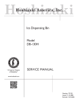
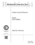
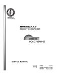
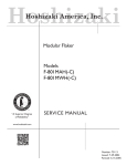
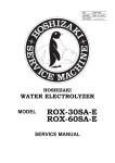
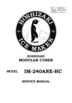
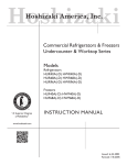
NO.
17EA-622 / 73106
ISSUED: FEB. 25, 2003
REVISED: JAN. 12, 2007
HOSHIZAKI
SELF-CONTAINED CUBER
MODEL
AM-100BAE
AM-150BAF
AM-150BWF
SERVICE MANUAL
IMPORTANT
Only qualified service technicians should attempt to service or maintain this icemaker.
No such service or maintenance should be undertaken until the technician has
thoroughly read this Service Manual.
HOSHIZAKI provides this manual primarily to assist qualified service technicians in the service
and maintenance of the icemaker.
Should the reader have any questions or concerns which have not been satisfactorily
addressed, please call or write to the HOSHIZAKI Technical Support Department for
assistance.
HOSHIZAKI AMERICA, INC.
618 Highway 74 South
Peachtree City, GA 30269
Attn: HOSHIZAKI Technical Support Department
Phone: 1-800-233-1940 Technical Service
(770) 487-2331
Fax: (770) 487-3360
NOTE: To expedite assistance, all correspondence/communication MUST include the
following information:
• Model Number
• Serial Number
• Complete and detailed explanation of the problem
CONTENTS
PAGE
I. SPECIFICATIONS ------------------------------------------------------------------------------------1. DIMENSIONS/CONNECTIONS----------------------------------------------------------------[a] AM-100BAE -----------------------------------------------------------------------------------[b] AM-150BAF ------------------------------------------------------------------------------------[c] AM-150BWF -----------------------------------------------------------------------------------2. SPECIFICATIONS --------------------------------------------------------------------------------[a] AM-100BAE -----------------------------------------------------------------------------------[b] AM-150BAF ------------------------------------------------------------------------------------[c] AM-150BWF ------------------------------------------------------------------------------------
1
1
1
2
3
4
4
5
6
II. GENERAL INFORMATION -------------------------------------------------------------------------- 7
1. CONSTRUCTION ---------------------------------------------------------------------------------- 7
[a] AM-100BAE ------------------------------------------------------------------------------------ 7
[b] AM-150BAF ------------------------------------------------------------------------------------- 8
[c] AM-150BWF ------------------------------------------------------------------------------------ 9
2. ICEMAKING COMPARTMENT ---------------------------------------------------------------- 10
III. INSTALLATION AND OPERATING INSTRUCTIONS ---------------------------------------- 11
1. CHECKS BEFORE INSTALLATION---------------------------------------------------------- 11
2. LOCATION ------------------------------------------------------------------------------------------ 12
3. SET UP---------------------------------------------------------------------------------------------- 13
4. ELECTRICAL CONNECTIONS ---------------------------------------------------------------- 13
5. WATER SUPPLY AND DRAIN CONNECTIONS ------------------------------------------- 14
6. FINAL CHECK LIST ------------------------------------------------------------------------------ 16
7. START UP ------------------------------------------------------------------------------------------ 16
8. PREPARING THE ICEMAKER FOR LONG STORAGE (more than 1 day) ---------- 17
IV. MAINTENANCE AND CLEANING INSTRUCTIONS ---------------------------------------- 19
1. CLEANING INSTRUCTIONS ------------------------------------------------------------------- 19
[a] WATER SYSTEM ----------------------------------------------------------------------------- 19
[b] STORAGE BIN, SLOPE, SCOOP, ETC. ------------------------------------------------ 21
2. MAINTENANCE ----------------------------------------------------------------------------------- 23
3. WATER VALVE ------------------------------------------------------------------------------------ 24
4. BIN CONTROL THERMOSTAT ---------------------------------------------------------------- 25
V. TECHNICAL INFORMATION ---------------------------------------------------------------------- 26
1. WATER CIRCUIT AND REFRIGERANT CIRCUIT ----------------------------------------- 26
[a] AM-100BAE ----------------------------------------------------------------------------------- 26
[b] AM-150BAF ------------------------------------------------------------------------------------ 27
[c] AM-150BWF ----------------------------------------------------------------------------------- 28
2. WIRING DIAGRAM ------------------------------------------------------------------------------- 29
[a] AM-100BAE ----------------------------------------------------------------------------------- 29
[b] AM-150BAF ------------------------------------------------------------------------------------ 30
[c] AM-150BWF ----------------------------------------------------------------------------------- 31
i
3. CONTROLS ---------------------------------------------------------------------------------------- 32
[a] ICEMAKING CONTROL --------------------------------------------------------------------- 32
[b] DEFROST CONTROL ----------------------------------------------------------------------- 32
[c] NO ADJUSTMENT REQUIRED ----------------------------------------------------------- 32
[d] ADJUSTMENT AT PART REPLACEMENT -------------------------------------------- 32
4. TIMING CHART ------------------------------------------------------------------------------------ 34
5. PERFORMANCE DATA------------------------------------------------------------------------- 35
[a] AM-100BAE ----------------------------------------------------------------------------------- 35
[b] AM-150BAF ------------------------------------------------------------------------------------ 36
[c] AM-150BWF ----------------------------------------------------------------------------------- 37
VI. SERVICE DIAGNOSIS ---------------------------------------------------------------------------- 38
1. NO ICE PRODUCTION -------------------------------------------------------------------------- 38
2. LOW ICE PRODUCTION ------------------------------------------------------------------------ 40
3. ABNORMAL ICE ---------------------------------------------------------------------------------- 40
4. OTHERS -------------------------------------------------------------------------------------------- 41
VII. ADJUSTMENT -------------------------------------------------------------------------------------- 42
1. EXPANSION VALVE - AM-150BAF ONLY -------------------------------------------------- 42
2. WATER REGULATING VALVE - WATER-COOLED MODEL ONLY ------------------ 43
VIII. REMOVAL AND REPLACEMENT ------------------------------------------------------------- 44
1. SERVICE FOR REFRIGERANT LINES ----------------------------------------------------- 44
[a] SERVICE INFORMATION ------------------------------------------------------------------ 44
[b] REFRIGERANT RECOVERY -------------------------------------------------------------- 45
[c] EVACUATION AND RECHARGE --------------------------------------------------------- 46
2. COMPRESSOR ----------------------------------------------------------------------------------- 47
3. DRIER ----------------------------------------------------------------------------------------------- 48
4. EVAPORATOR ------------------------------------------------------------------------------------ 49
5. HOT GAS VALVE --------------------------------------------------------------------------------- 50
6. PUMP MOTOR ------------------------------------------------------------------------------------ 51
7. FAN MOTOR --------------------------------------------------------------------------------------- 51
8. WATER VALVE ------------------------------------------------------------------------------------ 52
9. CONTROLLER BOARD ------------------------------------------------------------------------- 52
10. THERMISTOR FOR CUBE CONTROL ------------------------------------------------------ 53
11. BIN CONTROL THERMOSTAT ---------------------------------------------------------------- 54
12. EXPANSION VALVE - AM-150BAF/BWF ONLY ------------------------------------------ 55
13. WATER REGULATING VALVE - WATER-COOLED MODEL ONLY ------------------ 56
[a] VALVE BODY --------------------------------------------------------------------------------- 56
[b] WHOLE VALVE ------------------------------------------------------------------------------- 57
ii
I. SPECIFICATIONS
1. DIMENSIONS/CONNECTIONS
[a] AM-100BAE
1
[b] AM-150BAF
2
[c] AM-150BWF
3
2. SPECIFICATIONS
[a] AM-100BAE
AC SUPPLY VOLTAGE
AMPERAGE
MINIMUM CIRCUIT AMPACITY
MAXIMUM FUSE SIZE
115/60/1
6.5A (5 Min. Freeze AT 104°F/ WT 80°F)
N/A
N/A
APPROXIMATE ICE PRODUCTION
PER 24 HR.
lbs./day (kg/day)
SHAPE OF ICE
ICE PRODUCTION PER CYCLE
APPROXIMATE STORAGE CAPACITY
Ambient
Water Temp. (°F)
Temp. (°F)
50
70
70
105 (48)
103 (47)
80
96 (44)
93 (42)
90
86 (39)
83 (38)
100
67 (31)
66 (30)
Cube
ø20 x H27mm
1.54 lbs. (0.70 kg) 60 pcs.
44 Ibs.
ELECTRIC & WATER CONSUMPTION
ELECTRIC
W (KWH/100 lbs.)
WATER gal./24HR (gal./100 lbs.)
90°F/70°F
490 (15.7)
31 (38)
EXTERIOR DIMENSIONS (W x D x H)
EXTERIOR FINISH
WEIGHT
CONNECTIONS - ELECTRIC
- WATER SUPPLY
- DRAIN
24.9” x 20.5” x 38.7” (633 x 520 x 982mm)
Includes 6” leg
Stainless Steel, Galvanized Steel (Rear)
Net 110 lbs. (50 kg)
Shipping 150 lbs. (68 kg)
Cord Connection
Inlet
Fitting size is a 1/2” FPT (Water Inlet 3/4” BSP)
Outlet 3/4” FPT
CUBE CONTROL SYSTEM
HARVESTING CONTROL SYSTEM
ICE MAKING WATER CONTROL
COOLING WATER CONTROL
BIN CONTROL SYSTEM
Thermistor, Timer
Hot gas, Thermistor
Timer
N/A
Thermostat
COMPRESSOR
CONDENSER
EVAPORATOR
REFRIGERANT CONTROL
REFRIGERANT CHARGE
Hermetic, Model QA110K27CAU6
Air-cooled, Fin and Tube type
Tin-plated copper tube on sheet and cells
Capillary Tube
R134a 6.6 oz. (185 g)
COMPRESSOR PROTECTION
Auto-reset Overload Protector
ACCESSORIES - SUPPLIED
- REQUIRED
Ice Scoop, 6” Leg (4 pcs)
N/A
OPERATION CONDITIONS
VOLTAGE RANGE
AMBIENT TEMP.
WATER SUPPLY TEMP.
WATER SUPPLY PRESS.
DRAWING NO. (DIMENSIONS)
3X6975
70°F/50°F
430 (9.9)
38 (37)
90
96 (43)
86 (39)
76 (35)
61 (28)
See details of
PERFORMANCE DATA
No. SS-01129
104 - 127 V
50 - 100°F
41 - 90°F
7 - 113 PSIG
* We reserve the right to make changes in specifications and design without prior notice.
4
[b] AM-150BAF
AC SUPPLY VOLTAGE
AMPERAGE
MINIMUM CIRCUIT AMPACITY
MAXIMUM FUSE SIZE
115/60/1
8.8A (5 Min. Freeze AT 104°F/ WT 80°F)
N/A
N/A
APPROXIMATE ICE PRODUCTION
PER 24 HR.
lbs./day (kg/day)
SHAPE OF ICE
ICE PRODUCTION PER CYCLE
APPROXIMATE STORAGE CAPACITY
Ambient
Water Temp. (°F)
Temp. (°F)
50
70
90
70
150 (68)
140 (64)
130 (59)
80
140 (64)
130 (59)
120 (55)
90
130 (59)
120 (55)
110 (50)
100
110 (51)
105 (48)
100 (45)
Cube
ø20 x H27mm
1.87 lbs. (0.85 kg) 60 pcs.
88 Ibs.
ELECTRIC & WATER CONSUMPTION
ELECTRIC
W (KWH/100 lbs.)
WATER gal./24HR (gal./100 lbs.)
90°F/70°F
710 (14.2)
36 (31)
EXTERIOR DIMENSIONS (W x D x H)
EXTERIOR FINISH
WEIGHT
CONNECTIONS - ELECTRIC
- WATER SUPPLY
- DRAIN
27.7” x 28” x 38.8” (703 x 710 x 986mm)
Includes 6” leg
Stainless Steel, Galvanized Steel (Rear)
Net 143 lbs. (65 kg)
Shipping 185 lbs. (84 kg)
Cord Connection
Inlet
Fitting size is a 1/2” FPT (Water Inlet 3/4” BSP)
Outlet 3/4” FPT
CUBE CONTROL SYSTEM
HARVESTING CONTROL SYSTEM
ICE MAKING WATER CONTROL
COOLING WATER CONTROL
BIN CONTROL SYSTEM
Thermistor, Timer
Hot gas, Thermistor
Timer
N/A
Thermostat
COMPRESSOR
CONDENSER
EVAPORATOR
REFRIGERANT CONTROL
REFRIGERANT CHARGE
Hermetic, Model ASE24C3E
Air-cooled, Fin and Tube type
Tin-plated copper tube on sheet and cells
Expansion Valve
R404A 9.5 oz. (270 g)
70°F/50°F
660 (10.6)
44 (31)
See details of
PERFORMANCE DATA
No. SS-01131
COMPRESSOR PROTECTION
Auto-reset Overload Protector
REFRIGERANT CIRCUIT PROTECTION Auto-reset High Pressure Control Switch
ACCESSORIES - SUPPLIED
- REQUIRED
Ice Scoop, 6” Leg (4 pcs)
N/A
OPERATION CONDITIONS
VOLTAGE RANGE
AMBIENT TEMP.
WATER SUPPLY TEMP.
WATER SUPPLY PRESS.
DRAWING NO. (DIMENSIONS)
3X6976
104 - 127 V
50 - 100°F
41 - 90°F
7 - 113 PSIG
* We reserve the right to make changes in specifications and design without prior notice.
5
[c] AM-150BWF
AC SUPPLY VOLTAGE
AMPERAGE
MINIMUM CIRCUIT AMPACITY
MAXIMUM FUSE SIZE
115/60/1
7.0A (5 Min. Freeze AT 104°F/ WT 80°F)
N/A
N/A
APPROXIMATE ICE PRODUCTION
PER 24 HR.
lbs./day (kg/day)
SHAPE OF ICE
ICE PRODUCTION PER CYCLE
APPROXIMATE STORAGE CAPACITY
Ambient
Water Temp. (°F)
Temp. (°F)
50
70
90
70
150 (68)
140 (64)
130 (60)
80
150 (68)
140 (64)
130 (60)
90
145 (66)
140 (64)
130 (60)
100
145 (66)
135 (62)
125 (58)
Cube
ø20 x H27mm
1.78 lbs. (0.81 kg) 60 pcs.
88 Ibs.
ELECTRIC & WATER CONSUMPTION
ELECTRIC
W (KWH/100 lbs.)
WATER gal./24HR (gal./100 lbs.)
WATER-COOLED CONDENSER
90°F/70°F
560 (9.5)
43 (31)
196 (140)
EXTERIOR DIMENSIONS (W x D x H)
27.7” x 28” x 38.8” (703 x 710 x 986mm)
Includes 6” leg
Stainless Steel, Galvanized Steel (Rear)
Net 138 lbs. (63 kg)
Shipping 180 lbs. (82 kg)
Cord Connection
Inlet
Fitting size is a 1/2” FPT (Water Inlet 3/4” BSP)
Outlet 3/4” FPT
Inlet
1/2” FPT
Outlet 3/8” FPT
EXTERIOR FINISH
WEIGHT
CONNECTIONS - ELECTRIC
- WATER SUPPLY
- DRAIN
- COOLING WATER
70°F/50°F
560 (9.0)
48 (31)
138 (92)
See details of
PERFORMANCE DATA
No. SS-01769
CUBE CONTROL SYSTEM
HARVESTING CONTROL SYSTEM
ICE MAKING WATER CONTROL
COOLING WATER CONTROL
BIN CONTROL SYSTEM
Thermistor, Timer
Hot gas, Thermistor
Timer
N/A
Thermostat
COMPRESSOR
CONDENSER
EVAPORATOR
REFRIGERANT CONTROL
REFRIGERANT CHARGE
Hermetic, Model ASE24C3E
Water-cooled, Tube in Tube type
Tin-plated copper tube on sheet and cells
Expansion Valve
R404A 9.5 oz. (270 g)
COMPRESSOR PROTECTION
Auto-reset Overload Protector
REFRIGERANT CIRCUIT PROTECTION Auto-reset High Pressure Control Switch
ACCESSORIES - SUPPLIED
- REQUIRED
Ice Scoop, 6” Leg (4 pcs)
N/A
OPERATION CONDITIONS
VOLTAGE RANGE
AMBIENT TEMP.
WATER SUPPLY TEMP.
WATER SUPPLY PRESS.
DRAWING NO. (DIMENSIONS)
3X6976
104 - 127 V
50 - 100°F
41 - 90°F
7 - 113 PSIG
* We reserve the right to make changes in specifications and design without prior notice.
6
II. GENERAL INFORMATION
1. CONSTRUCTION
[a] AM-100BAE
Top Panel
Front Panel (Upper)
Ice Making Mechanism
Bin Control Thermostat
Storage Bin
Slope
Door
Front Panel (Lower)
Control Box
Condenser
Air Filter
Tapped Hole (Leg Mounting)
Control Switch
Fuse
7
[b] AM-150BAF
Top Panel
Ice Making Mechanism
Separator
Water Tank
Bin Control Thermostat
Slope
Door
Storage Bin
Front Panel (Lower)
Control Box
Condenser
Air Filter
Tapped Hole (Leg Mounting)
Control Switch
Fuse
8
[c] AM-150BWF
Top Panel
Ice Making Mechanism
Separator
Water Tank
Bin Control Thermostat
Slope
Door
Storage Bin
Front Panel (Lower)
Control Box
Condenser
Tapped Hole (Leg Mounting)
Control Switch
Fuse
9
2. ICEMAKING COMPARTMENT
Bracket
Evaporator
Separator
Ice Chute
Pump Motor
Water Plate
Water Tank
10
III. INSTALLATION AND OPERATING INSTRUCTIONS
1. CHECKS BEFORE INSTALLATION
* Visually inspect the exterior of the shipping container, and any severe damage noted should
be reported to the carrier.
WARNING
1. Remove shipping tape(s) and packing as follows. If any left in the icemaker,
it will not work properly.
2. Do not lift or carry the unpacked icemaker by using the brass fitting for water
supply at the rear of the unit. The plastic threads may be damaged.
IMPORTANT
1. Remove the shipping tapes holding the Door and Separator.
2. Ensure all components, fasteners and thumbscrews are securely in place.
* Remove the package containing accessories.
* Check that refrigerant lines do not rub or touch lines or other surfaces.
* Check that the Compressor is snug on all mounting pads.
* See the Nameplate on the upper right part of the Left Side Panel, and check that your
voltage supplied corresponds with the voltage specified on the Nameplate.
Ice Making Mechanism
Separator
Shipping Tape
Nameplate
Door
Shipping Tape
Accessories
Compressor
Mounting Pad
Fig. 1
11
2. LOCATION
WARNING
This icemaker is not intended for outdoor use. Normal operating ambient
temperature should be within 50°F (10°C) to 100°F (38°C); Normal operating
water temperature should be within 41°F (5°C) to 90°F (32°C). Operation of
the icemaker, for extended periods, outside of these normal temperature ranges
may affect production capacity.
For best operating results:
* The icemaker should not be located next to ovens, grills or other high heat producing
equipment.
* The location should provide a firm foundation for the equipment. Level the icemaker from
side to side and front to rear.
* Avoid a site where dripping is not allowed.
* This icemaker will not work at subfreezing temperatures. To prevent damage to the water
supply line, drain the icemaker when air temperature is below zero.
* The AM-100BAE icemaker requires no clearance at either side. But allow enough space at
rear for water supply and drain connections and at least 12” (approx. 30 cm) clearance at
front.
* The AM-150BAF icemaker requires 2” (approx. 5 cm) clearance at either side. Allow enough
space at rear for water supply and drain connections and at least 12” (approx. 30 cm)
clearance at front.
12
3. SET UP
IMPORTANT
Do not place heavy objects exceeding 33 lbs (15 kg) on the Top Panel.
1) Unpack the icemaker, and remove all shipping cartons, tapes
and packing BEFORE operating the unit.
2) Position the icemaker in a selected site. Clean the interior
with soap and water and rinse thoroughly.
3) Level the icemaker in both the left-to-right and the front-torear directions (when installed with or without legs). See Fig.
2.
Max. 0.4” (1 cm)
Fig. 2
4) When installing the unit without legs, the perimeter where the
machine touches the counter should be sealed with silicone
to prevent water from leaking under the icemaker.
Tapped Hole
(Leg Mounting)
5) When installing the unit with legs on the bottom, use the four
accessory legs adjustable from 6” (15.2 cm) to 7” (17.8 cm).
Screw the legs tightly into the tapped holes in the base (see
Fig. 3). Handle the icemaker carefully not to damage the
exterior.
Base
Adjustable Leg
Fig. 3
4. ELECTRICAL CONNECTIONS
WARNING
THIS APPLIANCE MUST BE GROUNDED.
This icemaker requires a ground that meets the national and local electrical
code requirements. To prevent possible severe electrical shock injury to
individuals or extensive damage to equipment, install a proper ground wire to
this icemaker. Remove the plug from the mains socket before any maintenance,
repairs or cleaning is undertaken.
* This icemaker must be plugged into the separated power receptacle which has enough
capacity. The maximum allowable voltage variation should not exceed ± 10 percent of the
nameplate rating. See the Nameplate.
* Usually an electrical permit and services of a licensed electrician are required.
13
5. WATER SUPPLY AND DRAIN CONNECTIONS
WARNING
To prevent damage to the freezer mechanism, do not operate this icemaker
when the water supply is OFF, or if the pressure is below 10 PSIG (0.7 bar), the
recommended water pressure. Stop the icemaker until proper water pressure
is resumed.
CAUTION
1. A brass fitting for the water supply line connection is attached to the 3/4” BSP
plastic threads to avoid cross-threading of the Water Valve possibly resulting
in leaks. The brass fitting allows connection of a 1/2” FPT that should be
connected to the potable water supply line.
2. While making the water supply line connection, use a wrench to hold the
brass fitting still to prevent overtightening and damage to the plastic threads.
* Water supply inlet for the icemaker is 1/2” female pipe thread (FPT).
Note: On water-cooled model, two water supply inlets are provided. One is for the icemaker
(1/2” FPT), and the other is for the water-cooled condenser (1/2” FPT).
* The brass fitting is attached as shown in Fig. 4. The fitting size is a 1/2” FPT and must be
connected only to a potable water supply.
* A water supply line shut-off valve and drain valve must be installed.
* Water supply pressure should be a minimum of 10 PSIG (0.7 bar) and a maximum of 113
PSIG (7.5 bar). If the pressure exceeds 113 PSIG (7.5 bar), use a pressure reducing valve.
* Drain outlet for icemaker dump is 3/4” FPT.
Note: On water-cooled model, a 3/8” FPT is provided for the condenser drain outlet. The
icemaker drain and the condenser drain piping connections must be made separately.
* Drain must be 1/4” fall per foot (2 cm fall per meter) on horizontal runs to get good flow.
* Keep a more than 2 vertical inch (5 vertical cm) air gap between the drain pipe end and the
sink.
* The drain pipe must be so laid as to prevent a backflow into the Storage Bin. Provide a trap
in the bin drain line to prevent odor from flowing back into the Storage Bin.
14
* A plumbing permit and services of a licensed plumber may be required in some areas.
* This icemaker should be installed in accordance with applicable national, state and local
regulations.
AM-100BAE
AM-150BAF
Icemaker
Water Supply Inlet
3/4” BSP Threads
Brass fitting is attached
to Water Supply Inlet.
Fitting size is a 1/2” FPT.
Shut-off Valve
Drain Valve
Bin Drain Outlet
3/4” FPT
Trap
1/4” fall per foot
To approved floor drain
AM-150BWF
Icemaker
Water Supply Inlet
3/4” BSP Threads
Condenser Outlet
3/8” FPT
Brass fitting is attached
to Water Supply Inlet.
Fitting size is a 1/2” FPT.
Water-cooled
Condenser Inlet
1/2” FPT
Shut-off Valve
Drain Valve
Bin Drain Outlet 3/4” FPT
1/4” fall per foot
Drain Valve
To approved floor drain
Shut-off Valve
Trap
Fig. 4
15
6. FINAL CHECK LIST
1) Is the icemaker level?
2) Is the icemaker in a site where the ambient temperature is within 50°F (10°C) to 100°F
(38°C) and the water temperature within 41°F (5°C) to 90°F (32°C) all year around?
3) Have all shipping tape(s), string and packing been removed from the icemaker?
4) Are all components, fasteners and thumbscrews securely in place?
5) Have all electrical and piping connections been made?
6) Has the power supply voltage been tested or checked against the nameplate rating?
Has a proper earth been installed to the icemaker?
7) Are the Water Supply Line Shut-off Valve and Drain Valve installed? Has the water supply
pressure been checked to ensure a minimum of 10 PSIG (0.7 bar) and a maximum of
113 PSIG (7.5 bar)?
8) Have the Compressor hold-down bolts and all refrigerant lines been checked against
vibration and possible failure?
9) Has the Bin Control Thermostat been checked for correct operation? When the icemaker
is running, cool the Detector of the Bin Control Thermostat. The icemaker should stop
within 10 seconds.
10) Has the user been given the Instruction Manual and instructed on how to operate the
icemaker and the importance of periodic maintenance recommended?
11) Has the user been given the name and telephone number of the Authorized Service
Agency?
7. START UP
* Check that shipping tape(s), string and packing are removed before starting the icemaker.
1) Clean inside the Storage Bin and Door.
2) Open the Water Supply Line Shut-off Valve and plug in the icemaker.
3) Remove the Front Panel (Lower), and move the Control Switch on the Control Box to the
“ICE” position.
* The freezing cycle will start automatically.
16
8. PREPARING THE ICEMAKER FOR LONG STORAGE (more than 1
day)
WARNING
Drain the icemaker to prevent damage to the water supply line at subfreezing
temperatures, using air or carbon dioxide. Shut off the icemaker until proper air
temperature is resumed.
[1] On water-cooled model only, first remove the water from the water-cooled condenser:
1) Remove the Front Panel (Lower).
Icemaker
Potable Water
Supply Line
2) Move the Control Switch, on the Control
Box, to the “OFF” position.
3) Wait 3 minutes.
Shut-off Valve
4) Move the Control Switch to the “ICE”
position.
5) Allow 5 minutes for the icemaker to fill with
water and the Water Pump to start
operating.
Drain Valve
Air or CO2
Water-cooled Condenser
Shut-off Valve
6) Close the Water-cooled Condenser Water Supply Line
Water Supply Line Shut-off Valve.
7) Open the Drain Valve for the water-cooled
condenser water supply line.
Drain Valve
Air or CO2
Fig. 5
8) Allow the line to drain by gravity.
9) Attach compressed air or carbon dioxide supply to the Condenser Water Line Drain
Valve.
10) Blow the water-cooled condenser out using compressed air or carbon dioxide until water
stops coming out.
[2] Remove the water from the potable water supply line and the Water Tank:
1) Close the Water Supply Line Shut-off Valve, and open the Drain Valve.
2) Remove the Front Panel (Lower), and move the Control Switch, on the Control Box, to the
“OFF” position.
17
3) Blow out the water supply line.
Note: This procedure is necessary to protect the icemaker from freezing up at subfreezing
temperature.
4) Unplug the icemaker.
5) Remove all ice from the Storage Bin, and clean the Bin.
6) Drain and clean the Water Tank. See “IV. 1. [b] STORAGE BIN, SLOPE, SCOOP, ETC.”
7) Refit the Front Panel (Lower) in its correct position.
8) Close the Drain Valve.
18
IV. MAINTENANCE AND CLEANING INSTRUCTIONS
IMPORTANT
Ensure all components, fasteners and thumbscrews are securely in place after
any maintenance or cleaning is done to the equipment.
1. CLEANING INSTRUCTIONS
WARNING
1. HOSHIZAKI recommends cleaning this unit at least once a year. More
frequent cleaning, however, may be required in some existing water conditions.
2. To prevent injury to individuals and damage to the icemaker, do not use
ammonia type cleaners.
3. Always wear liquid-proof gloves for safe handling of the cleaning and sanitizing
solutions. This will prevent irritation in case the solution comes into contact
with skin.
[a] WATER SYSTEM
1) Dilute approximately 5 fl. oz. (148 ml) of recommended cleaner Hoshizaki “Scale Away”
or “LIME-A-WAY” (Economics Laboratory, Inc.) with 1 gal. (3.8 lit.) of water.
2) Remove all ice from the Evaporator and the Storage Bin.
Note: To remove cubes on the Evaporator, remove the Front Panel (Lower), move the
Control Switch on the Control Box to the “OFF” position and move it back to the
“ICE” position after 3 minutes. The defrost cycle starts and the cubes will be
removed from the Evaporator.
3) Move the Control Switch to the “OFF” position. Close the Water Supply Line Shut-off
Valve.
4) Remove the Water Tank to drain the water. Refit the Water Tank in its correct position.
5) Slowly pour the cleaning solution into the Water Tank.
6) Move the Control Switch to the “WASH” position.
7) After circulating the cleaning solution for about 30 minutes, move the Control Switch to the
“OFF” position.
19
8) Remove the Water Tank to drain the cleaning solution. Refit the Water Tank in its correct
position.
9) Open the Shut-off Valve.
10) Move the Control Switch to the “WASH” position to circulate clean water for about 5
minutes.
11) Move the Control Switch to the “OFF” position and immediately back to the “WASH”
position to rinse water.
12) Repeat the above rinse procedure three more times to rinse thoroughly.
13) Dilute approximately 0.5 fl. oz. (14.8 ml) of 5.25% Sodium Hypochlorite (Chlorine Bleach)
with 1 gal. (3.8 lit.) of water.
14) Move the Control Switch to the “OFF” position. Close the Water Supply Line Shut-off
Valve.
15) Remove the Water Tank to drain the water. Refit the Water Tank in its correct position.
16) Slowly pour the sanitizing solution into the Water Tank.
17) Move the Control Switch to the “WASH” position.
18) After circulating the sanitizing solution for about 15 minutes, move the Control Switch to
the “OFF” position.
19) Remove the Water Tank to drain the sanitizing solution. Refit the Water Tank in its correct
position.
20) Open the Shut-off Valve.
21) Move the Control Switch to the “WASH” position to circulate clean water for about 5
minutes.
22) Move the Control Switch to the “OFF” position and immediately back to the “WASH”
position to rinse water.
23) Repeat the above rinse procedure two more times to rinse thoroughly.
24) Move the Control Switch to the “ICE” position, and start the automatic icemaking process.
Refit the Front Panel (Lower) in its correct position.
20
[b] STORAGE BIN, SLOPE, SCOOP, ETC.
IMPORTANT
1. Wash your hands before removing ice. Use the Plastic Scoop provided to
remove ice.
2. Keep the Scoop clean. Clean it by using a neutral cleaner at least once a
day, and rinse thoroughly.
3. Close the Bin Door after removing ice to prevent entrance of dirt, dust or
insects into the Bin.
4. Clean the Bin Liner at least once a month by using a neutral cleaner. Rinse
thoroughly after cleaning.
5. The Storage Bin is for ice use only. Do not store anything else in the Bin.
6. Keep the area around the icemaker clean. Dirt, dust or insects in the icemaker
could cause electrical damage to the equipment or harm to individuals.
1) Remove the Front Panel (Lower), and move the Control Switch on the Control Box to the
“OFF” position.
2) Unplug the icemaker.
3) Open the Bin Door, and remove ice from the Storage Bin.
4) Remove the Slope by bending its center carefully and releasing it from the two Slope
Shafts. Take out the Slope from the Storage Bin.
5) Thoroughly clean and sanitize the Storage Bin, Slope, Scoop and any parts normally
accessible from the Storage Bin.
6) Remove each Separator by lifting it to the
horizontal position and pushing it hard inward.
Remove all the Separators in the same way,
and clean and sanitize them.
Separator
7) Disconnect the Suction Tube from the Water
Tank to drain the Tank.
Water Tank
Suction Tube
21
8) Remove the Thumbscrews on both sides of the
Water Tank, and pull it out toward you. Clean
and sanitize the Water Tank.
Water Tank
Thumbscrew
9) Pull the Discharge Tube from the Water Plate.
Remove the Water Plate by pulling it toward you.
Water Plate
Discharge Tube
10) Remove the Caps to clean and sanitize the
Water Plate. If the Nozzles are clogged, clean
them with a wire or a suitable brush.
Cap
Water Plate
11) Refit the Caps on the Cleaning Outlets to seal
them off.
Cap
Water Plate
Water Plate
12) Slide in the Water Plate along the Mechanism
Base. Refit the Discharge Tube securely on
the Spray Outlet. A loose fitting may cause a
water leak.
Discharge Tube
13) Place the rear of the Water Tank on the Water
Tank Rest at the back of the Storage Bin. Use
the Thumbscrews to secure the front of the
Water Tank to the Mechanism Base.
Mechanism Base
Bin Rear
Tank Rest
Thumbscrew
Water Tank
14) Refit the Suction Tube on to the Water Tank Inlet.
A loose fitting may cause a water leak.
Water Tank
Suction Tube
22
15) Hook each Separator on to the Mechanism
Base, and pull it hard toward you until it locks in
place with a click. Refit all the Separators in
the same way.
Separator
16) Refit the Slope in its correct position.
17) Plug in the icemaker, and move the Control Switch on the Control Box to the “ICE” position
to start the automatic icemaking process.
18) Refit the Front Panel (Lower) in its correct position.
2. MAINTENANCE
IMPORTANT
This icemaker must be maintained individually, referring to the instruction manual
and labels provided with the icemaker.
1) Exterior
To keep the exterior clean, wipe occasionally with a clean and soft cloth. Use a damp
cloth containing a neutral cleaner to wipe off all oil or dirt build-up.
2) Air Filter
A plastic mesh air filter removes dirt or dust from the air, and keeps the Condenser
from getting clogged. As the filter gets clogged, the icemaker’s performance will be
reduced. Check the filter at least twice a month. When clogged, use warm water and
a neutral cleaner to wash the filter.
3) Condenser
Check the Condenser once a year, and clean if required by using a brush or vacuum
cleaner. More frequent cleaning may be required depending on the location of the
icemaker.
23
3. WATER VALVE
1) Unplug the icemaker or disconnect the power source.
2) Close the water supply tap.
3) Remove the Top Panel and Door.
4) Disconnect the Water Supply Inlet from the Water Valve.
5) Remove the Mesh Filter from the Water Valve.
6) Clean the Mesh using a brush.
7) Refit the Mesh and Water Supply Inlet in their correct positions.
8) Open the water supply tap.
9) Plug in the icemaker or connect the power source.
10) Check for leaks.
11) Refit the panels in their correct positions.
Coil
Filter
Do not remove
Fig. 6
24
4. BIN CONTROL THERMOSTAT
Bin Control Thermostat Replacement Procedure
To ensure proper operation, follow the instructions below:
1) Make a 40 mm (1.6”) diameter loop.
2) Locate the loop below the Thermostat Capillary (Bulb).
3) Manually bend the Capillary to keep it 15 mm (0.6”) forward from the through hole
position on the Holder.
4) Turn up the end of the Capillary.
Holder
Through Hole
Capillary (Bulb) End
Loop
15 mm (0.6”)
Capillary (Bulb)
40 mm (1.6”) DIA
Bin Control Thermostat Assembly Details
Thermostat
A
150mm
(5.9”)
Silicone Tube
210mm (8.3”)
Silicone Tube
Seal
Cord Heate
Flexible Tube
Capillary (Bulb)
DETAIL A
[NOTE]
1) Run Cord Heater along with Capillary of Thermostat and bind them tightly with
Aluminum Tape (Form end to end of Cord Heater).
2) Do not overheat Flexible Tube during shrinking process.
25
V. TECHNICAL INFORMATION
1. WATER CIRCUIT AND REFRIGERANT CIRCUIT
[a] AM-100BAE
Water Inlet
Capillary Tube
Accumulator
Evaporator
Water Plate
Drain Pan
Insulation
Pump
Motor
Insulation
Water Tank
Bin
Controller Board
Drier
Condenser
Fan
Compressor
Water Circuit
Refrigeration Circuit
26
Hot Gas
Valve
[b] AM-150BAF
Water Inlet
Expansion
Valve
Bulb
Evaporator
Water Plate
Water Tank
Pump
Motor
Drain Pan
Bin
Controller Board
Hot Gas
Valve
Compressor
Pressure
Switch
Fan
Drier
Condenser
Water Circuit
Refrigeration Circuit
27
[c] AM-150BWF
Water Inlet
Expansion
Valve
Bulb
Evaporator
Water Plate
Water Tank
Pump
Motor
Drain Pan
Bin
Controller Board
Hot Gas
Valve
Compressor
Pressure
Switch
Drier
Condenser
Water Regulator
Water Circuit
Refrigeration Circuit
28
2. WIRING DIAGRAM
[a] AM-100BAE
29
[b] AM-150BAF
30
[c] AM-150BWF
31
3. CONTROLS
[a] ICEMAKING CONTROL
The freeze and defrost cycles are controlled by the combination of a Thermistor and an
Electronic Controller.
When the Evaporator cools down to a specific temperature (around 27°F), the Thermistor
attached to the Evaporator senses the temperature and signals to the Electronic Controller.
After the built-in Timer counts 8 minutes from the signal input, the Controller switches the
contact of the built-in Relays (X1 and X2) to stop the Pump Motor and Fan Motor and to open
the Hot Gas Valve and Water Valve. This completes the freeze cycle and starts the defrost
cycle.
[b] DEFROST CONTROL
The ice cubes formed inside the Icemaking Cells are released by hot gas warming the
Evaporator. When a small portion of the ice melts on the Icemaking Cell interior, the ice
drops by its own weight and slides down the Ice Guide into the Storage Bin. When the
Evaporator is warmed further (to around 45°F), the Thermistor senses the temperature rise
and signals to the Electronic Controller. After the built-in Timer counts 50 seconds from the
signal input, the Controller switches the contact of the built-in Relays to start the Pump Motor
and Fan Motor and to close the Hot Gas Valve and Water Valve. This completes the defrost
cycle and starts the freeze cycle.
At low temperature conditions where the defrost cycle exceeds 102 seconds, the Water Valve
will close after 102 seconds.
In the initial cycle at startup or after shutdown for bin control, water is supplied for 102 seconds.
This means the Water Valve closes (approx. 50 seconds) after the freeze cycle starts.
[c] NO ADJUSTMENT REQUIRED
The Thermistor and Electronic Controller are factory adjusted to produce constant ice all the
year around, not affected by changes in the ambient and water temperatures.
No adjustment is required for any ambient temperature.
[d] ADJUSTMENT AT PART REPLACEMENT
Electronic Controller
The Thermistor and Electronic Controller
are designed for optimum ice production.
If adjustment is desired, follow the
instructions below.
Variable Resistor for
adjustment of freeze cycle
completion temperature
Fig. 7
32
Variable Resistor for
adjustment of defrost cycle
completion temperature
The Variable Resistor VR1 is for a fine adjustment of the defrost cycle completion temperature.
The Variable Resistor VR2 is for a fine adjustment of the freeze cycle completion temperature.
Turn VR2 clockwise for a higher temperature (WARM), i.e. ice cubes with larger diameter
holes and counterclockwise for a lower temperature (COLD), i.e. ice cubes with smaller
diameter holes.
Note: Do not adjust VR2 to the lowest temperature. It will cause excessive ice production
resulting in defrost failure.
When replacing the Controller Board, turn the Variable Resistor VR1 by 90° clockwise, and
leave VR2 as it is. See Fig. 8.
Marking (RED)
Variable Resistor for
adjustment of freeze cycle
completion temperature
Variable Resistor for
adjustment of defrost cycle
completion temperature
Fig. 8
33
ON
OFF
34
ON
OFF
X2
0°C
ON
OFF
ON
OFF
X1
Thermostat
(Evap. Temp.)
Electronic
Controller
Bin Control
Thermostat
OPEN
CLOSE
Hot Gas Valve
ON
OFF
Pump Motor
OPEN
CLOSE
ON
OFF
Fan Motor
Water Valve
ON
OFF
Compressor
Bin Control
ON
Thermostat Heate OFF
Power Cord
Power Switch
102sec
50sec
102sec
Defrost
Cycle
Freeze Cycle
(20 - 30 min.)
MAX 102sec
Defrost Cycle
(2 - 4 min.)
ON TIME: MAX 102sec
Freeze Cycle
(MAX STORAGE)
Shutdown
(Bin Control)
102sec
50sec
102sec
Defrost Freeze Cycle
Cycle
4. TIMING CHART
5. PERFORMANCE DATA
[a] AM-100BAE
APPROXIMATE
ICE PRODUCTION
PER 24 HR.
lbs./day (kg/day)
APPROXIMATE ELECTRIC
CONSUMPTION
Watts
APPROXIMATE WATER
CONSUMPTION PER 24 HR.
gal./day (m3/day)
FREEZING CYCLE TIME
min.
HARVEST CYCLE TIME
min.
HEAD PRESSURE
PSIG (kg/cm2G)
SUCTION PRESSURE
PSIG (kg/cm2G)
TOTAL HEAT OF REJECTION
Ambient
Water Temp. (°F)
Temp. (°F)
50
70
90
70
105 (48)
103 (47)
96 (44)
80
96 (44)
93 (42)
86 (39)
90
86 (39)
83 (38)
76 (35)
100
67 (31)
66 (30)
61 (28)
70
430
440
450
80
460
470
480
90
490
490
500
100
510
510
520
70
38 (0.15)
36 (0.14)
35 (0.14)
80
36 (0.14)
35 (0.14)
33 (0.13)
90
32 (0.13)
31 (0.12)
30 (0.12)
100
28 (0.11)
27 (0.11)
26 (0.10)
70
17
18
19
80
19
20
21
90
22
23
24
100
26.5
27.5
28.5
70
4
4
4
80
3
3
3
90
3
3
3
100
2.5
2.5
2.5
70
125 (0.86)
128 (0.88)
129 (0.89)
80
155 (1.07)
156 (1.08)
158 (1.09)
90
177 (1.22)
178 (1.23)
180 (1.24)
100
216 (1.49)
217 (1.50)
220 (1.52)
70
16 (0.11)
17 (0.12)
20 (0.14)
80
19 (0.13)
20 (0.14)
23 (0.16)
90
20 (0.14)
22 (0.15)
25 (0.17)
100
25 (0.17)
26 (0.18)
29 (0.20)
2400 BTU/h (AT 90°F /WT 70°F)
Note: The data without *marks should be used for reference.
35
[b] AM-150BAF
APPROXIMATE
ICE PRODUCTION
PER 24 HR.
lbs./day (kg/day)
APPROXIMATE ELECTRIC
CONSUMPTION
Watts
APPROXIMATE WATER
CONSUMPTION PER 24 HR.
gal./day (m3/day)
FREEZING CYCLE TIME
min.
HARVEST CYCLE TIME
min.
HEAD PRESSURE
PSIG (kg/cm2G)
SUCTION PRESSURE
PSIG (kg/cm2G)
TOTAL HEAT OF REJECTION
Ambient
Water Temp. (°F)
Temp. (°F)
50
70
90
70
150 (68)
140 (64)
130 (59)
80
140 (64)
130 (59)
120 (55)
90
130 (59)
120 (55)
110 (50)
100
110 (51)
105 (48)
100 (45)
70
660
670
690
80
670
690
710
90
680
710
730
100
700
720
750
70
44 (0.17)
46 (0.16)
43 (0.15)
80
43 (0.16)
43 (0.15)
36 (0.14)
90
40 (0.15)
36 (0.14)
34 (0.13)
100
36 (0.14)
34 (0.13)
30 (0.12)
70
14
15
16
80
15.5
17.5
18
90
17
18.5
19.5
100
17.5
19
20
70
3.8
3.8
3.8
80
3
3
3
90
2.5
2.5
2.5
100
2
2
2
70
240 (1.65)
243 (1.67)
244 (1.68)
80
269 (1.85)
270 (1.86)
273 (1.88)
90
299 (2.06)
301 (2.07)
303 (2.08)
100
339 (2.33)
340 (2.34)
342 (2.35)
70
58 (0.40)
58 (0.40)
58 (0.40)
80
59 (0.41)
59 (0.41)
59 (0.41)
90
61 (0.42)
61 (0.42)
61 (0.42)
100
62 (0.43)
62 (0.43)
62 (0.43)
2460 BTU/h (AT 90°F /WT 70°F)
Note: The data without *marks should be used for reference.
36
[c] AM-150BWF
APPROXIMATE
ICE PRODUCTION
PER 24 HR.
lbs./day (kg/day)
APPROXIMATE ELECTRIC
CONSUMPTION
Watts
APPROXIMATE WATER
CONSUMPTION PER 24 HR.
gal./day (m3/day)
FREEZING CYCLE TIME
min.
HARVEST CYCLE TIME
min.
HEAD PRESSURE
PSIG (kg/cm2G)
SUCTION PRESSURE
PSIG (kg/cm2G)
TOTAL HEAT OF REJECTION
Ambient
Water Temp. (°F)
Temp. (°F)
50
70
90
70
150 (68)
140 (64)
130 (60)
80
150 (68)
140 (64)
130 (60)
90
145 (66)
140 (64)
130 (60)
100
145 (66)
135 (62)
125 (58)
70
560
560
560
80
560
560
570
90
560
560
570
100
560
570
570
70
186 (0.70)
225 (0.85)
524 (1.98)
80
186 (0.70)
234 (0.89)
550 (2.08)
90
188 (0.71)
239 (0.90)
587 (2.22)
100
190 (0.72)
246 (0.93)
610 (2.31)
70
14
15
16.5
80
14.5
15
16.5
90
15
15
16.5
100
15
15.5
17
70
3
3
2.5
80
3
2.5
2.5
90
2.5
2.5
2.5
100
2.5
2.5
2.5
70
266 (1.84)
270 (1.86)
274 (1.89)
80
268 (1.85)
270 (1.86)
274 (1.89)
90
270 (1.86)
271 (1.87)
274 (1.89)
100
270 (1.86)
271 (1.87)
274 (1.89)
70
65 (0.45)
64 (0.44)
64 (0.44)
80
67 (0.46)
65 (0.45)
65 (0.45)
90
67 (0.46)
67 (0.46)
65 (0.45)
100
67 (0.46)
65 (0.45)
65 (0.45)
2720 BTU/h (AT 90°F /WT 70°F)
Note: The data without *marks should be used for reference.
37
VI. SERVICE DIAGNOSIS
1. NO ICE PRODUCTION
PROBLEM
[1] The icemaker
will not start.
CHECK
a) Control Switch
POSSIBLE CAUSE
1. OFF position.
2. Loose connections.
3. Bad contacts.
b) Power Cord
1. Loose connection.
2. Open circuit - damaged.
1. Blown out.
1. Tripped with Bin filled with
ice.
2. Fused contacts.
c) Fuse
d) Bin Control
Thermostat
e) High Pressure
Control
(150BAF/BWF)
f) Wiring to
Controller Board
g) Thermistor
h) Hot Gas Solenoid
Valve
i) Water Supply Line
(water-cooled)
j) Water Solenoid
Valve
[2] Compressor
will not start, or
operates
intermittently.
k) Controller Board
a) High Pressure
Control
(150BAF/BWF)
b) Water Regulator
(water-cooled)
c) Overload
Protector
1. Bad contacts.
1. Loose connections or
open.
1. Leads short-circuit.
1. Continues to open in
freeze cycle.
1. Water supply OFF and
water supply cycle does
not finish.
2. Condenser water
pressure too low or OFF
and Pressure Control
opens and closes
frequently.
1. Mesh filter or orifice gets
clogged and water supply
cycle does not finish.
2. Coil winding opened.
3. Wiring to Water Valve.
1. Defective.
1. Condenser water
temperature too warm
(water-cooled).
2. Refrigerant overcharged.
3. Condenser water
pressure too low or OFF
(water-cooled).
1. Set too high.
2. Clogged or defective.
1. Bad contacts.
2. Voltage too low.
38
REMEDY
1. Move to ICE position.
2. Tighten.
3. Check for continuity and
replace.
1. Tighten.
2. Repair or replace.
1. Replace.
1. Remove ice.
2. Check for continuity and
replace.
1. Check for continuity and
replace.
1. Check for continuity and
repair or replace.
1. Replace.
1. Check for power OFF in
freeze cycle and replace.
1. Check for recommended
pressure.
2. Check for recommended
pressure.
1. Clean.
2. Replace.
3. Check for loose
connection or open, and
replace.
1. Replace.
1. Check for recommended
temperature.
2. Recharge.
3. Check for recommended
pressure.
1. Adjust lower.
2. Clean or replace.
1. Check for continuity and
replace.
2. Check for recommended
voltage.
PROBLEM
[2] (Continued)
CHECK
d) Starter
e) Start Capacitor
f) Power Relay
(150BAF/BWF)
g) Compressor
h) Air Filter,
Condenser
a) Control Circuit
[3] Compressor
runs, but other
components will
not start.
[4] Fan Motor will
a) Wiring
not run.
b) Thermistor,
Controller Board
[5] Water
a) Water Solenoid
continues to be
Valve
supplied in
b) Controller Board
freeze cycle.
[6] Water does not a) Water Supply Line
circulate.
b) Water Solenoid
Valve
c) Water System
d) Pump Motor
e) Controller Board
f) Discharge Tube
[7] All components
run, but no ice
is produced.
a) Refrigerant
POSSIBLE CAUSE
3. Refrigerant overcharged
or undercharged.
1. Defective.
1. Defective.
1. Bad contacts.
2. Coil winding opened.
1. Wiring to Compressor.
2. Defective.
1. Clogged.
1. Replace.
1. Replace.
1. Check for continuity and
replace.
2. Replace.
1. Check for loose
connection or open, and
repair or replace.
2. Replace.
1. Clean.
1. Loose connection or
broken wire.
1. Repair or replace.
1. Loose connection or
broken wire.
1. Defective.
1. Repair or replace.
1. Diaphragm does not
close.
1. Defective.
1. Check for water leaks
with icemaker OFF.
1. Replace.
1. Water pressure too low
and water level in Water
Tank too low.
1. Dirty mesh filter or orifice
and water level in Water
Tank too low.
1. Water leaks.
1. Check for recommended
pressure.
2. Clogged.
1. Motor winding opened.
2. Bearing worn out.
3. Wiring to Pump Motor.
4. Defective or bound
impeller.
1. Defective.
1. Clogged.
2. Out of position.
1. Undercharged.
2. Air or moisture trapped.
b) Compressor
c) Hot Gas Solenoid
Valve
d) Expansion Valve
(150BAF/BWF)
REMEDY
3. Recharge.
1. Defective valve.
1. Continues to open in
freeze cycle.
1. Continues to close in
freeze cycle.
39
1. Replace.
1. Clean.
1. Check connections for
water leaks, and repair.
2. Clean.
1. Replace.
2. Replace.
3. Check for loose
connection or open, and
replace.
4. Replace and clean.
1. Replace.
1. Clean.
2. Place in position.
1. Check for leaks and
recharge.
2. Replace Drier, and
recharge.
1. Replace Compressor.
1. Check and replace.
1. Check and replace.
2. LOW ICE PRODUCTION
PROBLEM
[1] Freeze cycle
time is too long.
CHECK
a) Water Supply
b) Water
Temperature
c) Water Quality
d) Refrigerant
Charge
e) Refrigerant Circuit
f) Thermistor,
Controller Board
g) Air Filter,
Condenser
POSSIBLE CAUSE
1. Low pressure.
REMEDY
1. Check for recommended
pressure.
1. Too high.
1. Check for recommended
water temperature.
1. High hardness or contains 1. Install a water filter or
impurities.
scale treatment.
2. Lime is deposited inside
2. Clean.
Cooling Water Tubing.
1. Overcharged or
1. Recharge correctly and
undercharged.
check for leaks.
1. Excessive moisture.
1. Replace Drier and
recharge correctly.
1. Defective.
1. Replace.
1. Clogged.
1. Clean.
3. ABNORMAL ICE
PROBLEM
[1] Large-hole
cubes.
[2] Cloudy cubes.
CHECK
POSSIBLE CAUSE
a) Water Supply Line 1. Low pressure.
b) Ambient or Water
Temperature
c) Air Filter,
Condenser
d) Water Valve
e) Pump Motor
f) Refrigerant
Charge
g) Thermistor,
Controller Board
h) Expansion Valve
(150BAF/BWF)
a) Water Supply Line
b) Water Quality
c) Water Valve
d) Water System
e) Water Plate
f) Pump Motor
g) Thermistor,
Controller Board
1. Too high.
1. Clogged.
1. Clogged.
1. Leaks.
1. Undercharged.
REMEDY
1. Check for recommended
pressure.
1. Check for recommended
temperatures.
1. Clean.
1. Defective.
1. Clean.
1. Repair or replace.
1. Check for leaks and
recharge correctly.
1. Replace.
1. Poorly adjusted.
1. Readjust.
1. Low pressure.
1. Check for recommended
pressure.
2. Clogged.
2. Check Strainer and clean.
1. High hardness or contains 1. Install a water filter or
impurities.
scale treatment.
2. Lime is deposited inside
2. Clean.
Cooling Water Tubing.
1. Clogged.
1. Clean.
1. Scaled up.
1. Clean or remove scale.
1. Jet hole clogged.
1. Clean.
1. Leaks.
1. Replace.
2. Bearings worn out.
2. Replace.
1. Defective.
1. Replace.
40
4. OTHERS
PROBLEM
[1] Icemaker will
not stop when
Bin is filled with
ice.
[2] Abnormal noise
CHECK
a) Bin Control
Thermostat
b) Controller Board
POSSIBLE CAUSE
1. Fused contacts.
a) Pump Motor
b) Fan Motor
1. Bearing worn out.
1. Bearings worn out.
2. Fan Blade deformed.
3. Fan Blade does not move
freely.
1. Mounting pad out of
position.
1. Rubbing or touching on
other surfaces.
1. Plugged.
c) Compressor
d) Refrigerant Lines
[3] Ice in Storage
Bin often melts.
a) Bin Drain
1. Defective.
41
REMEDY
1. Check for continuity and
replace.
1. Replace.
1. Replace.
1. Replace.
2. Replace Fan Blade.
3. Replace.
1. Reinstall.
1. Secure or reset pipes.
1. Clean.
VII. ADJUSTMENT
1. EXPANSION VALVE - AM-150BAF/BWF ONLY
The Expansion Valve is factory-adjusted. Do not adjust it except at replacement or service.
Adjust the valve setting, if necessary, as follows:
1) Remove the Cap Nut.
2) Use a flat-blade screwdriver to rotate the Adjust Screw.
3) Watch holes of ice cubes produced. Standard setting is that Evaporator inlet side and
outlet side cubes have almost the same diameters. To make the inlet side larger, rotate
90 - 180° clockwise. Smaller, counterclockwise. Do not rotate more than 180° at a time.
CAUTION
Over adjustment of the valve may result in liquid refrigerant return causing freezing
to the suction line and severe damage to the Compressor.
Bulb
Adjust Screw
Capillary Tube
Cap Nut
Solder Connection
Fig. 9
42
2. WATER REGULATING VALVE - WATER-COOLED MODEL ONLY
The Water Regulating Valve is factory-adjusted. Do not adjust it except at replacement or
service. Adjust the valve setting, if necessary, as follows:
1) Attach a pressure gauge to high-side line, or prepare a thermometer to check Condenser
drain temperature.
2) Rotate the Adjust Screw using a flat blade screwdriver so that the pressure gauge shows
270 PSIG, or the thermometer reads 104 - 115°F, 5 minutes after Freeze Cycle starts.
When the pressure or temperature exceeds the above, rotate the Adjust Screw
counterclockwise.
3) Check that the pressure or temperature holds.
Adjust Screw
Adjust Screw
Valve Body
Top View
3/8-18NPT
Bellows
Capillary Tube
Fig. 10
43
VIII. REMOVAL AND REPLACEMENT
1. SERVICE FOR REFRIGERANT LINES
[a] SERVICE INFORMATION
1) Allowable Compressor Opening Time and Prevention of Lubricant Mixture [R134a/
R404A]
The compressor must not be opened more than 30 minutes in replacement or service. Do
not mix lubricants of different compressors even if both are charged with the same refrigerant,
except when they use the same lubricant.
2) Treatment for Refrigerant Leak [R134a/R404A]
If a refrigerant leak occurs in the low side of an ice maker, air may be drawn in. Even if the low
side pressure is higher than the atmospheric pressure in normal operation, a continuous
refrigerant leak will eventually lower the low side pressure below the atmospheric pressure
and will cause air suction. Air contains a large amount of moisture, and ester oil easily absorbs
a lot of moisture. If an ice maker charged with R134a/R404A has possibly drawn in air, the
drier must be replaced. Be sure to use a drier designed for R134a/R404A.
3) Handling of Handy Flux [R134a/R404A]
Repair of the refrigerant circuit needs brazing. It is no problem to use the same handy flux
that has been used for the current refrigerants. However, its entrance into the refrigerant
circuit should be avoided as much as possible.
4) Oil for Processing of Copper Tubing [R134a/R404A]
When processing the copper tubing for service, wipe off oil, if any used, by using alcohol or
the like. Do not use too much oil or let it into the tubing, as wax contained in the oil will clog the
capillary tubing.
5) Service Parts for R134a/R404A
Some parts used for refrigerants other than R134a/R404A are similar to those for R134a/
R404A. But never use any parts unless they are specified for R134a/R404A because their
endurance against the refrigerant have not been evaluated. Also, for R134a/R404A, do not
use any parts that have been used for other refrigerants. Otherwise, wax and chlorine remaining
on the parts may adversely affect R134a/R404A.
6) Replacement Copper Tubing [R134a/R404A]
The copper tubes currently in use are suitable for R134a/R404A. But do not use them if oily
inside. The residual oil in copper tubes should be as little as possible. (Low residual oil type
copper tubes are used in the shipped units.)
44
7) Evacuation, Vacuum Pump and Refrigerant Charge [R134a/R404A]
Never allow the oil in the vacuum pump to flow backward. The vacuum level and vacuum
pump may be the same as those for the current refrigerants. However, the rubber hose and
gauge manifold to be used for evacuation and refrigerant charge should be exclusively for
R134a/R404A.
8) Refrigerant Leak Check
Refrigerant leaks can be detected by charging the unit with a little refrigerant, raising the
pressure with nitrogen and using an electronic detector. Do not use air or oxygen instead of
nitrogen for this purpose, or rise in pressure as well as in temperature may cause R134a or
R404A to suddenly react with oxygen and explode. Be sure to use nitrogen to prevent explosion.
[b] REFRIGERANT RECOVERY
The refrigerant must be recovered if required by an applicable law. No refrigerant Access
Valve is provided in the unit. Install a proper Access Valve on the low-side line (ex. Compressor
Process Pipe). Recover the refrigerant from the Access Valve, and store it in a proper
container. Do not discharge the refrigerant into the atmosphere.
When replacing the Drier, take the opportunity to also fit a High-side Access Valve for ease of
charging liquid refrigerant.
45
[c] EVACUATION AND RECHARGE
1) Attach Charging Hoses, a Service Manifold and a Vacuum Pump to the system. If possible,
use Quick Release Connectors onto the Access Valves (especially on the high side).
2) Turn on the Vacuum Pump.
3) Allow the Vacuum Pump to pull down to a 29.9”Hg vacuum. Evacuating period depends
on the pump capacity.
4) Close the Low-side and High-side Valves on the Service Manifold.
5) Disconnect the Vacuum Pump, and attach a Refrigerant Charging Cylinder to accurately
weigh in the liquid charge. Remember to purge any air from the Charging Hose. See the
Nameplate for the required refrigerant charge.
6) Open the High-side Valve on the Gauge Manifold, and accurately measure in the liquid
charge. Close the valve on the Charging Cylinder before closing the High-side Manifold
Valve. Any remaining liquid in the line can be charged into the low side.
Note: Always charge in the liquid stage, as many refrigerants are blends and vapour
charging will affect the blend consistency (eg. R404A).
7) Turn on the icemaker. Release the High-side Access Connector, and allow pressure in
the charging line to slowly enter the low side of the system. Cap off the High-side Access
Valve. When pressure reduces on the low side, disconnect the low side charging line
and cap off the Access Valve.
8) Always cap the Access Valves to prevent a refrigerant leak.
9) Always thoroughly leak test all joints and valve caps.
10) Avoid charging large quantities of liquid into the low side in case of damage to the
Compressor.
Depressed
Cap
Access Valve
OPEN
Fig. 11
46
2. COMPRESSOR
1) Unplug the icemaker or disconnect the power source.
2) Remove the Rear Mesh and Front Panel..
3) Recover the refrigerant and store it in a proper container, if required by an applicable law
(See “1. [b] REFRIGERANT RECOVERY”).
4) Remove the Terminal Cover on the Compressor, and disconnect Solderless Terminals.
5) Disconnect the Discharge and Suction Pipes using brazing equipment.
6) Remove the Hold-down Bolts, Washers and Rubber Grommets.
7) Slide and remove the Compressor. Unpack the new Compressor package.
8) Attach the Rubber Grommets of the previous Compressor.
9) Clean the Suction and Discharge Pipes with an abrasive cloth/paper.
10) Place the Compressor in position, and secure it using the Bolts and Washers.
11) Remove Plugs from the Compressor Suction and Discharge Pipes.
12) Braze or solder the Access, Suction and Discharge lines (Do not change this order), with
nitrogen gas flowing at a pressure of 3 - 4 PSIG.
13) Install the new Drier (See “3. DRIER”).
14) Check for leaks using nitrogen gas (140 PSIG) and soap bubbles.
15) Evacuate the system and charge it with refrigerant (See “1. [c] EVACUATION AND
RECHARGE”).
16) Connect the Solderless Terminals and replace the Terminal Cover in its correct position.
17) Refit the panels in their correct positions.
18) Plug in the icemaker or connect the power source.
Note: Hoshizaki recommends that Compressor starting electrics are always replaced at the
same time as the Compressor.
47
3. DRIER
1) Unplug the icemaker or disconnect the power source.
2) Remove the Rear Mesh and Front Panel.
3) Recover the refrigerant and store it in a proper container, if required by an applicable law
(See “1. [b] REFRIGERANT RECOVERY”).
4) Remove the Drier Holder, if any, and pull the Drier toward you for easy service.
5) Remove the Drier using brazing equipment.
6) Braze or solder the new Drier, with the arrow on the Drier in the direction of the refrigerant
flow. Use nitrogen gas at a pressure of 3 - 4 PSIG when brazing tubings. Braze in an
Access Valve using a tee if necessary.
7) Check for leaks using nitrogen gas (140 PSIG) and soap bubbles.
8) Evacuate the system and charge it with refrigerant (See “1. [c] EVACUATION AND
RECHARGE”).
9) Refit the panels in their correct positions.
10) Plug in the icemaker or connect the power source.
Note: Always use a Drier of the correct capacity and refrigerant type.
48
4. EVAPORATOR
IMPORTANT
Always install a new Drier every time the sealed refrigeration system is opened.
Do not replace the Drier until after all other repair or replacement has been
made.
1) Unplug the icemaker or disconnect the power source.
2) Remove the Rear Mesh, Door, Top and Front Panels.
3) Recover the refrigerant and store it in a proper container, if required by an applicable law
(See “1. [b] REFRIGERANT RECOVERY”).
4) Remove the Water Tank and Water Plate, referring to “IV. 1. CLEANING.”
5) Remove the Thermistor Holder and Thermistor from the Evaporator.
6) Disconnect the solder connections on the Evaporator using brazing equipment. Protect
the surrounding components from heat damage.
7) Remove the four screws holding the Evaporator.
8) Install the new Evaporator, and secure it with the four original screws.
9) Remove and replace the Drier (See “3. DRIER”).
10) Braze pipes, with nitrogen gas flowing at a pressure of 3 - 4 PSIG.
11) Check for leaks using nitrogen gas (140 PSIG) and soap bubbles.
12) Refit the Thermistor (See “10. THERMISTOR FOR CUBE CONTROL”).
13) Evacuate the system and charge it with refrigerant (See “1. [c] EVACUATION AND
RECHARGE”).
14) Refit the panels in their correct positions.
15) Plug in the icemaker or connect the power source.
49
5. HOT GAS VALVE
IMPORTANT
Always install a new Drier every time the sealed refrigeration system is opened.
Do not replace the Drier until after all other repair or replacement has been
made.
1) Unplug the icemaker or disconnect the power source.
2) Remove the Rear Mesh and Front Panel.
3) Recover the refrigerant and store it in a proper container, if required by an applicable law
(See “1. [b] REFRIGERANT RECOVERY”).
4) Disconnect the Hot Gas Valve leads.
5) Remove the screw and the Solenoid Coil.
6) Remove the valve and Drier using brazing equipment.
7) Braze the new Hot Gas Valve with nitrogen gas flowing at a pressure of 3 - 4 PSIG.
WARNING
Always protect the valve body by using a damp cloth to prevent the valve from
overheating. Do not braze with the valve body exceeding 248°F.
8) Install the new Drier (See “3. DRIER”).
9) Check for leaks using nitrogen gas (140 PSIG) and soap bubbles.
10) Evacuate the system and charge it with refrigerant (See “1. [c] EVACUATION AND
RECHARGE”).
11) Attach the Solenoid Coil to the valve body, and secure it with the screw.
12) Connect the leads.
13) Refit the panels in their correct positions.
14) Plug in the icemaker or connect the power source.
50
6. PUMP MOTOR
1) Unplug the icemaker or disconnect the power source.
2) Remove the Top Panel, Door and Front Panel.
3) Disconnect the Pump Motor leads behind the Evaporator.
4) Drain the Water Tank by compressing the plastic tabs on the Suction Tube to release the
Joint.
5) Spread the tabs on both sides of the Water Tank and pull it toward you.
6) Carefully remove the plastic housing by releasing the retaining screws.
7) Disconnect the Pump Suction and Discharge Tubings.
8) Release the pump retaining screws to remove the Pump.
9) Install the new motor in the reverse order of the removal procedure.
10) Plug in the icemaker or connect the power source, and check for leaks.
11) Refit the panels in their correct positions.
7. FAN MOTOR
1) Unplug the icemaker or disconnect the power source.
2) Remove the Front Panel.
3) Disconnect the Connector of the Fan Motor.
4) Remove the Fan Motor Bracket and the Fan Motor.
5) Cut the leads of the Fan Motor allowing enough lead length to reconnect using closed end
connectors.
6) Install the new Fan Motor in the reverse order of the removal procedure.
7) Refit the panels in their correct positions.
9) Plug in the icemaker or connect the power source.
51
8. WATER VALVE
1) Close the water supply tap.
2) Unplug the icemaker or disconnect the power source.
3) Remove the Top Panel and Front Panel.
4) Disconnect the Receptacle (leads) from the Water Valve.
5) Remove the Valve Outlet tubing.
6) Remove the Water Supply Inlet and Water Valve by releasing the two retaining screws.
7) Install the new valve in the reverse order of the removal procedure.
8) Open the water supply tap.
9) Plug in the icemaker or connect the power source.
10) Check for leaks.
11) Refit the panels in their correct positions.
Note: When replacing parts, disassemble as shown in Fig. 6 (page 24) and replace the
defective parts.
9. CONTROLLER BOARD
1) Unplug the icemaker or disconnect the power source.
2) Remove the Front Panel.
3) Remove screws and the Control Box Cover.
4) Pull out the Control Box from the machine compartment, and disconnect the Connectors
on the Controller Board.
5) Pull out and remove the Controller Board from the Control Box.
6) Install the new Controller Board and reassemble the Control Box in the reverse order of
the removal procedure.
7) Refit the panel in its correct position.
8) Plug in the icemaker or connect the power source.
52
10. THERMISTOR FOR CUBE CONTROL
1) Unplug the icemaker or disconnect the power source.
2) Remove the Top and Front Panels, Pipe Cover (Rear) and Control Box Cover.
3) Remove the Connectors on the Controller Board, referring to “9. CONTROLLER BOARD.”
4) Unscrew and remove the Thermistor Holder and Thermistor, located on the Evaporator.
5) Install the new thermistor in the reverse order of the removal procedure, by using a sealant
(High-thermal Conduct Type). See Fig. 12.
Note: Recommended sealant is KE4560RTV, manufactured by SINETSU SILICON.
When other type of sealant used, the cube size and performance will be changed.
Do not use silicone sealant as this will insulate the Thermistor.
Sealant
Sealant
Holder
Holder
* Thermistor and Leads are FRAGILE.
HANDLE WITH CARE.
Holder
Screw
* Leads
* Thermistor
Fig. 12
53
Evaporator
IMPORTANT
When replacing the Thermistor, wrap the Thermistor Bulb with aluminum foil
tape [1”(25mm) W x 0.6”(15mm) L].
1) Wrap a turn with an overlap of 0.1 - 0.2” (3 - 5mm).
2) Make the aluminum foil tape tightly stick to the
Thermistor Bulb.
3) Keep the overlap of the aluminum foil tape away
from the Evaporator.
Evaporator
Overlap of
aluminum
foil tape
11. BIN CONTROL THERMOSTAT
1) Unplug the icemaker or disconnect the power source.
2) Remove the Top Panel, Door and Pipe Cover (Rear).
3) Remove the Thermostat Holder from the Storage Bin, and disconnect the the Bin Control
Thermostat Bulb.
4) Remove the Bin Control Thermostat from the icemaker body (rear).
5) Install the new Bin Control Thermostat in the reverse order of the removal procedure.
6) Refit the panels in their correct positions.
7) Plug in the icemaker or connect the power source.
54
12. EXPANSION VALVE - AM-150BAF/BWF ONLY
IMPORTANT
Always install a new Drier every time the sealed refrigeration system is opened.
Do not replace the Drier until after all other repair or replacement has been
made.
1) Unplug the icemaker or disconnect the power source.
2) Remove the Top, Front and Rear Mesh Panels.
3) Recover the refrigerant and store it in a proper container, if required by an applicable law
(See “1. [b] REFRIGERANT RECOVERY”).
4) Remove the Expansion Valve using brazing equipment. Protect the Evaporator and pipes
from excessive heat with damp cloths or similar.
5) Remove the Expansion Valve Sensor (Bulb).
6) Remove the Drier using brazing equipment.
7) Braze in the new Expansion Valve. Protect the body of the valve from excessive heat, and
use nitrogen at a pressure of 3 - 4 PSIG when brazing.
8) Braze or solder the new Drier (See “3. DRIER”).
9) Check for leaks using nitrogen gas (140 PSIG) and soap bubbles.
10) Evacuate the system and charge it with refrigerant (See “1. [c] EVACUATION AND
RECHARGE”).
11) Attach the Bulb to the suction line in position. Be sure to secure it using a wire or clamp
and replace the insulation.
12) Replace the panels in their correct positions.
13) Plug in the icemaker or connect the power source.
55
Bulb
Adjust Screw
Capillary Tube
Cap Nut
Solder Connection
Fig. 13
13. WATER REGULATING VALVE - WATER-COOLED MODEL ONLY
[a] VALVE BODY
1) Unplug the icemaker or disconnect the power source.
2) Close the water supply tap.
3) Remove the Rear Mesh and Front Panel.
4) Disconnect the flare connections of the Water Regulating Valve.
5) Remove the valve from the Bracket.
6) Install a new Water Regulating Valve.
7) Connect the flare connections.
8) Open the water supply tap.
9) Check for water leaks.
10) Replace the Rear Mesh and Front Panel in their correct positions.
11) Plug in the icemaker or connect the power source.
56
[b] WHOLE VALVE
IMPORTANT
Always install a new Drier every time the sealed refrigeration system is opened.
Do not replace the Drier until after all other repair or replacement has been
made.
1) Unplug the icemaker or disconnect the power source.
2) Close the water supply tap.
3) Remove the Rear Mesh and Front Panel.
4) Recover the refrigerant and store it in a proper container, if required by an applicable law
(See “1. [b] REFRIGERANT RECOVERY”).
5) Remove the Capillary Tube from the Copper Tube using brazing equipment.
6) Disconnect the flare connections from the Bracket.
7) Remove the screws and the valve from the Bracket.
8) Install the new valve, and insert the Capillary Tubes into the Copper Tube.
9) Web the Copper Tube end, and braze or solder the Copper Tube and Capillary Tubes
together.
10) Install the new Drier (See “3. DRIER”).
11) Check for leaks using nitrogen gas (140 PSIG) and soap bubbles.
12) Evacuate the system and charge it with refrigerant (See “1. [c] EVACUATION AND
RECHARGE”).
13) Connect the flare connections.
14) Open the water supply tap.
15) Check for water leaks.
16) Replace the panels in their correct positions.
17) Plug in the icemaker or connect the power source.
57
Adjust Screw
Valve Body
Flare
Connection
Bellows
Capillary Tube
Fig. 14
58
HOSHIZAKI AMERICA, INC.
618 HIGHWAY 74 SOUTH
PEACHTREE CITY, GA 30269
U.S.A.
PHONE: 770-487-2331
www.hoshizakiamerica.com
HOSHIZAKI ELECTRIC CO., LTD.
3-16 MINAMIYAKATA, SAKAE, TOYOAKE,
AICHI 470-1194 JAPAN
PHONE: 0562-97-2111