1
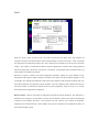
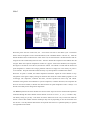
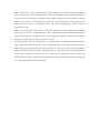
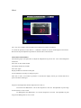
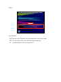
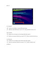
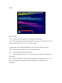
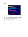
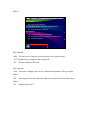
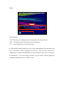
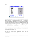
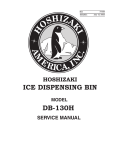
Slide 1 REACH-IN SAFETEMP (-AAC) FH1-AAC H O S H I Z A K I RH2-AAC-HD A M E R I C A The Hoshizaki line of reach- ins consists of two types of refrigerators and freezers. The high end TEMPGUARD (-SSB) and the mid-range SAFETEMP (–AAC). The TEMPGUARD has all the features that you would expect to find in a high-end box such as, solid state control system including alarm and error codes, stainless steel interiors, doors and exterior sides, etc. The unit also has other features found exclusively on Hoshizaki products such as the EverCheck™ control board system. The TEMPGUARD™ (-SSB) and SAFETEMP™ (-AAC) products are available in various configurations some of which are one, two, and three, section refrigerators, one and two section freezers, with half door and glass door options. Combination units are also available with refrigerators and freezers in the same unit. This module will concentrate on the SAFETEMP (-AAC). The TEMPGUARD –SSB will be covered in another module. At the end of this module you will find a table with detailed specifications for all current Reach-In models. Slide 2 -AAC REFRIGERATOR SEQUENCE H O S H I Z A K I A M E R I C A When the power switch is turned “ON”, the control board starts the delay timer and energizes the evaporator fan motor and frame heaters (if the “Perimeter Heater” switch is turned on). After 2.0 minutes the compressor and condenser fan motor start. The evaporator fan circulates air across the coil, and into the cabinet. The cabinet is cooled until the desired set-point temperature is reached. The average pull-down time for an empty box to the factory set point is 21~23 minutes. This pull-down time would obviously vary when product is included in the cabinet. When the set point is reached, the cabinet temperature thermistor signals the control module to stop refrigeration. This signal is simply a change of resistance that causes the control module program to re-act accordingly. (See Temperature Resistance chart below) The compressor and condenser fan motor will stop. The cabinet thermistor will signal the control module to cycle the compressor and condenser fan motor on and off as needed, to maintain the desired cabinet set point temperature. There is always a 2.0 minute restart delay for the refrigeration components. Defrost control: Defrost will initiate by temperature through the defrost thermistor. This thermistor is mounted in the evaporator, if it gets below 13ºF the unit will initiate a defrost cycle and de–energizing the compressor and condenser fan motor. The evaporator fan will continue to run. When the evaporator temperature has reached 40ºF the control module will cycle the compressor and condenser fan motor on and continue normal cycling. Slide 3 -AAC FREEZER SEQUENCE When the power switch is turned “ON”, the –AAC freezer will start in the defrost cycle. The defrost heaters will be energized as well as the frame heaters (if the “Perimeter Heater” switch is on). After the defrost thermistor that is mounted in the center of the coil, has reached 100°F the defrost heaters will deenergize and a five minute delay timer will start. After five minutes the compressor and condenser fan will energize. When the evaporator temperature reaches 0°F (Approx. 700O at the thermistor) the evaporator fan begins to circulate air across the coil, and into the cabinet. The cabinet is cooled until the desired setpoint temperature is reached. The average pull-down time for an empty box to the factory set point is 21~23 minutes. This pull-down time would obviously vary when product is included in the cabinet. When the set point is reached, the cabinet temperature thermistor signals the control module to stop refrigeration. This signal is simply a change of resistance that causes the control module program to re-act accordingly. The compressor, condenser fan motor, and the evaporator fan motor stop. The cabinet thermistor will signal the control module to cycle the compressor, condenser fan motor, and evaporator fan motor on and off as needed, to maintain the desired cabinet set point temperature. There is always a 2.5 minute restart delay for the refrigeration components. The defrost system for all freezer models uses electric heater strips and is time initiated and temperature terminated through the control module. Freezer defrost can be set to occur 1, 2, 3, 4, 6, or 8 times a day. The factory setting is 6 per day. This means an electric defrost will occur every 4 hours from when the freezer is started. The number of defrost needed per day will vary depending on how each customer uses the reach-in. You may find that more defrost are required if the reach-in is opened frequently or operated in a high humid environment. When a defrost occurs, “dEF” will be displayed. During defrost, the evaporator fan motor, condenser fan motor, and compressor shut down and the electric heaters are energized. The heaters warm the evaporator coil to remove any ice build up. The defrost control thermistor signals the control module to terminate defrost, once the center of the evaporator coil reaches 100°F. This should indicate a clear evaporator coil. Remember that this 100°F is coil temperature and is not circulated throughout the cabinet because the evaporator fan is off. When the coil temperature reaches 100°F at the defrost thermistor, the control module de-energizes the defrost heaters and starts a 5 minute delay timer. After 5 minutes, the compressor and condenser fan motor restart and the evaporator coil begins to cool. Once the evaporator temperature reaches 0°F, the thermistor signals the control module to restart the evaporator fan motor. The electric defrost system is backed up by two additional safeties. A one hour maximum defrost timer starts counting when the defrost begins. If the coil temperature fails to reach 100°F within one hour, this back up timer will terminate defrost and re-start normal cycling. The second safety, a bi-metal switch also backs up the defrost system. This switch is mounted on the top of the evaporator coil. If the temperature at the top of the evaporator coil reaches 120°F, this switch opens to shut down the electric heaters. The control board will continue in defrost with no electric heaters until the one hour timer expires. Pressing the reset at the display panel will clear the E3 alarm. Slide 4 REACH-IN SAFETEMP (-AAC) CONTROL MODULE H O S H I Z A K I A M E R I C A The –AAC uses a simple control module and two thermistors (Cabinet and defrost) to control the operation of the reach-in. A different controller is used for the Refrigerator and freezer. However the setpoint adjustment procedure is done the same on both controls SET POINT ADJUSTMENT: The following steps will explain how to adjust the temperature set point on the –AAC series Refrigerator and Freezer. Press “Set” on the control module The display should now read SP1 Press “Set” again Display should now read Current Set point Use the UP/Down arrow keys to change set point Press “Set” to store. If no button is pressed in 15 seconds, the display will not go to normal and the set point will remain unchanged. Set point is the temperature that the compressor will come on. For Freezers the differential is -6°F for the compressor to turn off. The adjustable set point range for the Freezers is -10°F to 28°F. For Refrigerators the differential is -5°F for the compressor to turn off. The adjustable set point range for the Refrigerators is 37°F to 55°F. Slide 5 -AAC CONTROLLER ADJUSTMENT •Accessing: •Press the “F” Key and the “Down Arrow Key” together •Screen will go blank for 2 seconds then begin the control menu. Press Together H O S H I Z A K I A M E R I C A There are several menu items that can be adjusted in the-AAC control module. However the system was designed and tested with the factory default settings. Therefore only adjustments to set point and defrost frequency (Freezer only) are recommended. In the event that adjustments are needed use the following chart to view these adjustments. To access this menu press the [ ] and the [°F] buttons and release. To advance to the next display press [°F] Slide 6 -AAC REFRIGERATOR CONTROLLER ADJUSTMENT •1st Command: •“dif” Indicates Cabinet differential setting •“-06” Factory setting for Refrigerator •2nd Command: •“HI” Maximum Setpoint • “28” Default for Refrigerator in °F •3rd Command: •“LO” Minimum Setpoint •“-10” Default for Refrigerator in °F H O S H I Z A K I A M E R I C A 1st Command: “dIF” Indicates next display is cabinet differential setting “-05” Indicates cabinet differential is set for -5°F Factory default for refrigerator is -5°F 2nd Command: “HI” Indicates the next display is the maximum allowable setpoint “55” Indicates a maximum allowable set point of 55°F which is default for refrigerator. 3rd Command: “LO” Indicates the next display is the minimum allowable set point “37” Indicates a minimum allowable set point of 37°F which is default for refrigerator. Slide 7 -AAC REFRIGERATOR CONTROLLER ADJUSTMENT •4th Command: •“CAL” Thermistor calibration. •“XX” When replacing Thermistor place Thermistor end in ice water and confirm that Display reads 32°F. If not adjust setting. •5th Command: •“def” 1st command concerning Defrost Cycle •“In1” Defrost initiation temperature •“13” Defrost will initiate at 13 degrees H O S H I Z A K I A M E R I C A 4th Command: “CAL” Indicates the next display is for calibration of the thermistor. “XX” When replacing thermistor, place thermistor end in an ice water bath of 32°F and confirm that the display reads 32°F. If not adjust setting. 5th Command: “dEF” The next series of displays refer to the defrost initiation temperature “In1” The next display shows initiation temperature “13” Defrost will initiate at 13°F. This is default for refrigerators. Slide 8 -AAC REFRIGERATOR CONTROLLER ADJUSTMENT •6th Command: •“Def” Second command concerning defrost • “End” Defrost termination temperature • “40” Defrost will terminate at 40°F •7th Command: •“Sho” Short Cycle Protection •“CyC” Minimum time Compressor must remain OFF •“02” 2 Minute minimum OFF time H O S H I Z A K I A M E R I C A 6th Command: “dEF” The next series of displays refer to the defrost termination temperature “End” Next display shows defrost termination temperature “40” Defrost will terminate at 40°F. This is default for refrigerators. 7th Command: “SH0” The next series of displays refer to the Short Cycle Protection “CyC” Minimum time Compressor must remain OFF “02” 2 Minute minimum OFF time Slide 9 -AAC REFRIGERATOR CONTROLLER ADJUSTMENT •8th Command: •“COI” •“Sen” Temperature of defrost sensor •“20” Actual temperature of the Defrost Sensor in °F WARNING WARNING This unit has been tested with its default settings. Under normal conditions the only values that should be adjusted are the Setpoint and Defrost frequency H O S H I Z A K I A M E R I C A 8th Command: “COI” The next series of displays refer to the temperature of the defrost sensor “SEn” The next display shots actual defrost thermistor temperature “20” Actual temperature of the defrost sensor in °F Slide 10 -AAC FREEZER CONTROLLER ADJUSTMENT •1st Command: •“dif” Indicates cabinet differential setting •“-06” Factory setting for Freezer •2nd Command: •“HI” Maximum Setpoint • “28°F” Default for Freezer •3rd Command: •“LO” Minimum Setpoint •“-10°F” Default for Freezer H O S H I Z A K I A M E R I C A 1st Command: “dIF” Indicates next display is cabinet differential setting “-06” Indicates cabinet differential is set for -6°F Factory default for freezer -6°F 2nd Command: “HI” Indicates the next display is the maximum allowable setpoint “28” Indicates a maximum allowable set point of 28°F Which is default for the freezer. 3rd Command: “LO” Indicates the next display is the minimum allowable setpoint “-10” Indicates a minimum allowable set point of -10°F which is default for the refrigerator. Slide 11 -AAC FREEZER CONTROLLER ADJUSTMENT •4th Command: •“CAL” Thermistor Calibration. •“XX” When replacing thermistor place Thermistor end in ice water and confirm that display reads 32°F. If not adjust setting. •5th Command: •“def” 1st Command concerning Defrost Cycle •“04” Defrost frequency in hours (ex. 1 Defrost cycle every 4 hours) H O S H I Z A K I A M E R I C A 4th Command: “CAL” Indicates the next display is for calibration of the thermistor. “XX” When replacing thermistor place thermistor end in an ice water bath of 32°F and confirm that the display reads 32°F. If not adjust setting. 5th Command: (Ok to adjusting depending on box application and defrost needs) “dEF” The next series of displays refer to the defrost frequency “Int” The next display shows defrost interval “4” Defrost frequency in hours (ex. 1 Defrost cycle every 4 hours or 6 defrost per 24 hour period) Note: The defrost frequency can be adjusted by using the up and down arrow keys. You must cycle through the remaining steps in this menu before any changes will be recognized. Slide 12 -AAC FREEZER CONTROLLER ADJUSTMENT •6th Command: •“def” 2nd Command concerning Defrost •“dur” Maximum allowable time for Defrost •“60” Equals 60 minute maximum Defrost •7th Command: •“def” 3rd Command concerning Defrost •“HI” Defrost termination temperature •“100” Defrost will terminate at 100°F H O S H I Z A K I A M E R I C A 6th Command: “dEF” The next series of displays refer to the maximum allowable time for defrost “dur” The next display shows maximum defrost duration “60” Equals 60 minute maximum Defrost 7th Command: “dEF” The next series of displays refer to the defrost termination temperature “HI” The next display shows the defrost temperature in °F. “100” Defrost will terminate at 100°F Slide 13 -AAC FREEZER CONTROLLER ADJUSTMENT •8th Command: •“Sho” Short Cycle Protection •“CyC” Minimum time compressor must remain OFF •“02” 2 Minute minimum OFF time •9th Command: •“Fan” Concerns Evaporator fan operation •“HI” Re-Initiation temperature of Evap. Fan after defrost •“00” Default setting is 0°F H O S H I Z A K I A M E R I C A 8th Command: “SH0” The next series of displays refer to the short cycle protection time. “CyC” Minimum time compressor must remain off. “02” 2 Minute minimum OFF time. 9th Command: “FAn” Next series of displays refer to the re-Initiation temperature of Evap. fan after defrost. “HI” Next display shows the temperature that the evaporator fan will energize after a defrost. “00” Default Setting is 0°F. Slide 14 -AAC FREEZER CONTROLLER ADJUSTMENT •10th Command: •“COI” •“Sen” Temperature of Defrost Sensor •“20” Actual Temperature of the Defrost Sensor in °F WARNING WARNING This unit has been tested with its default settings. Under normal conditions the only values that should be adjusted are the Setpoint and Defrost frequency H O S H I Z A K I A M E R I C A 10th Command: “COI” The next series of displays refer to temperature of the defrost Sensor. “SEn” Next display shows actual defrost sensor temperature. “20” Actual Temperature of the defrost Sensor We hope that this training module gives you a basic understanding of the operation of the –AAC SafeTemp™ reach- in refrigerators and freezers. You can access copies of the complete Service Manual at hoshizakiamerica.com or for hard copies please contact your local distributor. If you need further assistance you can contact Technical Support at [email protected] or 1-800-233-1940.