1
NO.
X007-793
ISSUED: FEB. 12, 2010
REVISED:
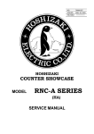
HOSHIZAKI
WATER ELECTROLYZER
MODEL
ROX-30SA-E
ROX-60SA-E
SERVICE MANUAL
CONTENTS
PAGE
I. GENERAL INFORMATION---------------------------------------------------------------------------1
1. SAFETY INSTRUCTIONS--------------------------------------------------------------------------1
2. PRODUCT INFORMATION------------------------------------------------------------------------3
[a] FEATURES-----------------------------------------------------------------------------------------3
[b] MODEL NAME------------------------------------------------------------------------------------4
3. DIMENSIONS/SPECIFICATIONS----------------------------------------------------------------5
[a] ROX-30SA-E---------------------------------------------------------------------------------------5
[b] ROX-60SA-E---------------------------------------------------------------------------------------6
II. TECHNICAL INFORMATION------------------------------------------------------------------------7
1. PRINCIPLE OF ELECTROLYSIS-----------------------------------------------------------------7
2. TEMPERATURE CORRECTION FUNCTION----------------------------------------------- 10
3. CONSTRUCTION----------------------------------------------------------------------------------- 13
[a] EXTERIOR--------------------------------------------------------------------------------------- 13
[b] INTERIOR---------------------------------------------------------------------------------------- 14
[c] MECHANISM------------------------------------------------------------------------------------ 15
[d] CONTROL BOX--------------------------------------------------------------------------------- 17
[e] OPERATION PANEL--------------------------------------------------------------------------- 18
[f] CONTROL PANEL (A) (B)-------------------------------------------------------------------- 19
[g] WATER SOFTENER TIMER----------------------------------------------------------------- 19
4. FUNCTIONS AND OPERATION---------------------------------------------------------------- 20
[a] NORMAL MODE-------------------------------------------------------------------------------- 20
[b] ADJUSTMENT MODE------------------------------------------------------------------------- 20
[c] CHECK MODE---------------------------------------------------------------------------------- 21
5. WATER SOFTENER------------------------------------------------------------------------------- 26
[a] DISCHARGE VOLUME----------------------------------------------------------------------- 26
[b] REGENERATION PROCESS--------------------------------------------------------------- 28
6. NEUTRALIZER-------------------------------------------------------------------------------------- 30
7. WATER CIRCUIT----------------------------------------------------------------------------------- 31
8. WIRING DIAGRAM--------------------------------------------------------------------------------- 33
III. SERVICE INFORMATION------------------------------------------------------------------------- 34
1. MAINTENANCE/INSPECTION------------------------------------------------------------------ 34
2. ERROR CODES------------------------------------------------------------------------------------ 35
3. SERVICE DIAGNOSIS---------------------------------------------------------------------------- 37
4. REMOVAL AND REPLACEMENT OF COMPONENTS----------------------------------- 39
[a] FRONT COVER--------------------------------------------------------------------------------- 39
[b] ELECTROLYTIC CELL------------------------------------------------------------------------ 40
[c] NEUTRALIZER---------------------------------------------------------------------------------- 42
[d] SALT WATER TANK--------------------------------------------------------------------------- 43
[e] WATER SOFTENER--------------------------------------------------------------------------- 44
[f] CONTROL BOX--------------------------------------------------------------------------------- 45
5. INSTALLATION AND SAFETY PRECAUTIONS-------------------------------------------- 46
[a] VENT LINES------------------------------------------------------------------------------------- 46
[b] NEUTRALIZER---------------------------------------------------------------------------------- 47
[c] SALT----------------------------------------------------------------------------------------------- 47
IV. AUTOMATIC DISPENSING VALVE VDW-2PB-E (OPTION)----------------------------- 48
1. DIMENSIONS/SPECIFICATIONS-------------------------------------------------------------- 48
2. CONSTRUCTION----------------------------------------------------------------------------------- 49
[a] VALVE UNIT------------------------------------------------------------------------------------- 49
[b] OPERATION PANEL--------------------------------------------------------------------------- 50
3. DISPENSING MODES AND OPERATION--------------------------------------------------- 51
4. ADJUSTMENT--------------------------------------------------------------------------------------- 52
[a] STANDARD SETTINGS---------------------------------------------------------------------- 52
[b] OPTIONAL SETTINGS (OPTION REQUIRED)---------------------------------------- 53
[c] SERVICE SETTINGS-------------------------------------------------------------------------- 54
V. REMOTE CONTROLLER ROX-RCUA (OPTION)------------------------------------------- 56
1. DIMENSIONS/SPECIFICATIONS-------------------------------------------------------------- 56
2. INSTALLATION INSTRUCTIONS-------------------------------------------------------------- 57
ii
In the context of this manual, the term "sanitizing water" refers to acidic water and
"cleaning water" refers to alkaline water.
I. GENERAL INFORMATION
1. SAFETY INSTRUCTIONS
The following instructions contain important safety precautions and should be strictly
observed. The terms used here are defined as follows:
WARNING: There is a possibility of death or serious injury to the service person and
a third party or the user due to improper service operations or defects in
serviced products.
CAUTION: There is a possibility of injury to the service person and a third party or the
user or damage to their property* due to improper service operations or
defects in serviced products.
* The term “damage to their property” here refers to extensive damage to household
effects, houses and pets.
WARNING
1. When there is no need to energize the unit during disassembly or cleaning, be sure to
unplug the unit or disconnect the main power supply before servicing the unit to prevent
electric shocks.
2. If the unit must be energized for inspection of the electric circuit, use rubber gloves to
avoid contact with any live parts, which may result in electric shocks.
3. Check for proper earth connections, and repair if necessary to prevent electric shocks.
4. Always use service parts intended for the applicable model for replacement of defective
parts. Use proper tools to secure the wiring. Otherwise abnormal operation or trouble
may occur and cause electric leaks or fire.
5. Check for proper part installations, wiring conditions and soldered or solderless terminal
connections to avoid smoke, fire or electric shocks.
6. Be sure to replace damaged or deteriorated power cords and lead wires to prevent
electric shocks, flames or smoke.
7. Lead wires using solderless terminals or the like must be bound with their closed ends
up to avoid entrance of moisture that could lead to electric leaks or fire.
8. After servicing, always use a megohmmeter (500VDC) to check for the insulation
resistance of minimum 1 megohm between the live part (attachment plug) and the dead
metal part (earth terminal). Negligence in checking may cause electric leaks or shocks.
9. Do not service the electrical parts with wet hands to prevent electric leaks or shocks.
10. Always ask the user to keep children away from the work area. They may be injured by
tools or disassembled products.
CAUTION
1. After servicing, be sure to check for water leaks from the water supply and drain lines to
prevent wetting the surrounding properties.
2. After servicing, always check for proper operation.
CAUTION LABEL LOCATION
The following caution labels are attached where special care should be taken.
On top panel
Inside door
On remote controller (option)
On bottom front of control box
2. PRODUCT INFORMATION
[a] FEATURES
1) Built-in neutralizer
The neutralizer is provided inside the unit to facilitate installation.
2) Flow rate
ROX-30SA-E: 1.5 - 3.0L/min
ROX-60SA-E: 3.0 - 6.0L/min
3) Standardized high pump head specification
The standardized 0.1MPa pressure switch allows for long pipe installation. Do not
change the following settings.
Pressure switch:
Flow rate switch:
0.1MPa
1.5 - 2.0L/min
4) No air chamber drain required
The relief valve is provided to eliminate periodical air chamber drain and drain valve
installation (water check valve is still required outside the unit).
5) Improved salt water tank door
The salt water tank door has been redesigned to prevent salt from spilling inside the
unit.
6) Salt water tank overflow hose
In case the salt water tank overflow pipe clogs, the overflow hose prevents salt water
from flowing out of the entire salt water tank by leaking salt water from a single spot
(bottom panel mesh near neutralizer).
7) No valve required for downstairs water delivery
No electric ball valve installation is required to deliver electrolyzed water downstairs.
8) 25A vents
To meet the demand for increased ventilation capacity, another vent has been added
for the netralizer and the vent size has been changed from 20A to 25A.
9) Production starts only by turning on power switch
Just turn on the power switch (earth leakage circuit breaker) to start producing
electrolyzed water. There is no need to press the ON/OFF switch. In case of
instantaneous power failure, the unit automatically resumes production.
10) Independent controls by systemized components
Idependent controls are provided for operations of cell A, cell B (ROX-60SA-E only),
left and right water pumps, and salt water level. Even if one unit stops with error, the
other keeps running and electrolyzed water is still available.
11) Common main control board
Both ROX-30SA-E and ROX-60SA-E use the same main control board with model
identification by provision of CN37 connector (ROX-30SA-E: provided, ROX-60SA-E:
not provided). Replacement of the main control board for ROX-30SA-E will require
reconnection of the CN37 connector to the new board.
12) New VDW automatic dispensing valve
The automatic sensor dispensing valve has been renewed to improve design and
user-friendliness. The LED lamps visually identify sanitizing water (red) and cleaning
water (blue).
13) Exclusive remote controller
The new LED remote controller ROX-RCUA-E allows tank water level check from a
remote site.
[b] MODEL NAME
ROX - 30 S A - E
Global specifications
Development order
System
Maximum flow rate (x0.1L/min)
Hoshizaki water electrolyzer
3. DIMENSIONS/SPECIFICATIONS
[a] ROX-30SA-E
[b] ROX-60SA-E
II. TECHNICAL INFORMATION
1. PRINCIPLE OF ELECTROLYSIS
Water (H2O) we use in our daily life has a mysterious power. Adding a small amount of salt
(NaCl) to water (H2O) and electrolyzing it with special electrodes will generate "electrolytic
oxidizing water (acidic water)" with strong oxidizing effects and "electrolytic reducing water
(alkaline water)" with strong reducing effects. Here we explain this electrolysis process and
the meaning of such terms as "pH" and "oxidization/reduction" which may sound unfamiliar.
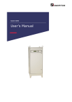
Electrolysis Process - See the diagram on the following page for the electrolysis
mechanism inside the electrolytic cell.
1) Electrolysis with a higher salt concentration around 5 - 20% is apt to generate chlorine
gas (Cl2) at the anode. The electrolyzer with a lower salt concentration around 0.07 0.15% is apt to generate hypochlorous acid (HOCl) at the anode.
2) At the anode, oxidization will generate hypochlorous acid (HOCl) and chlorine gas (Cl2).
3) At the cathode, reduction will generate hydrogen gas (H2) and sodium hydroxide (NaOH).
Oxidization/Reduction - Oxidization and reduction occur a the same time, while electrons
are transferred.
1) Oxidization - Reaction of a substance to emit electrons.
2) Reduction - Reaction of a substance to receive electrons.
Oxidization/Reduction Potential - Degree of liability to oxidization and reduction,
indicated in "mV".
1) Positive potential - An oxidizing agent (= a substance capable of oxidizing other
substances) is contained. The higher potential shows the higher tendency to oxidize
other substances.
2) Negative potential - An reducing agent (= a substance capable of reducing other
substances) is contained. The lower potential shows the higher tendency to reduce
other substances.
pH - Concentration index of hydrogen ions. pH7 means neutrality, the higher pH alkalinity,
and the lower pH acidity.
Flow of electrons
DC Power Supply
Sodium Hydroxide
(NaOH)
Hypochlorous Acid
(HOCl)
Electrolytic Cell
Anode
(OX)
Na
+
Positive ions drawn
to cathode
Diaphragm
Na
-
OH
Cathode
(RED)
+
Na
+
H2
HOCl
-
OH
2e
-
Na
Na
2e
-
H2O
Cl
-
H2O
Negative ions
drawn to anode
Cl
-
Salt Water (NaCl)
Reactions at Anode
Reactions
at Anode
Chloride ions (Cl-) and
hydroxide ions emit
-) to(Cl
Chloride (e
ions
and hydroxide
ions
electrons
the) anode,
which become
emit electrons
(e (HOCl).
) to the anode, which
hypochlorous
acid
become hypochlorous acid (HOCl).
Reactions at Cathode
Reactions
Cathode
+)atreceive
Sodium ions (Na
electrons -(e-)
+
Sodium
ions
(Na
)
receive
electrons
(e )
from the cathode and become sodium
from
cathode
and become
sodium
metalthe
(Na)
which reacts
with water
(H2O)
and
becomes
sodium
hydroxide
(NaOH)
metal (Na) which reacts with water (H2O)
and hydrogen gas (H2).
and becomes sodium hydroxide (NaOH)
and hydrogen gas (H2).
4
Salt water contains four kinds of ions; sodium ions (Na+), chlorine ions (Cl-), hydrogen ions
(H+) and hydroxide ions (OH-).
NaCl + H2O
→
(Mix water and salt)
Na+ + Cl- + H+ + OHSalt water (4 kinds of ions)
When two electrodes are inserted into salt water and voltage is applied:
Negative ions (Cl-) are drawn to the anode, and
Positive ions (Na+) are drawn to the cathode.
At the anode, hydrogen chloride (HCl) and hypochlorous acid (HOCl) are generated.
2Cl- + H2O →
HCl + HOCl + 2e-
Electrons (2e-) are emitted to the anode, which means the acid water (HCl + HOCl) causes
oxidization. [As electrons are emitted, the oxidization/reduction potential becomes positive
(+mV).]
Chlorine ions also emit electrons and become chlorine gas (Cl2).
2Cl- →
Cl2 + 2e(Cl2 = chlorine gas)
At the cathode, sodium hydroxide (NaOH) and hydrogen gas (H2) are generated.
Na+ + H2O + H+ + 2e-
→
NaOH + H2
Electrons (2e-) are received from the cathode, which means the alkali water (NaOH)
causes reduction. [As electrons are received, the oxidization/reduction potential becomes
negative (-mV).]
2. TEMPERATURE CORRECTION FUNCTION
Due to the properties of electrolyzed water, low water temperatures in winter may cause
excessively high available chlorine concentrations. For purpose of protection, a thermistor
is provided to detect water temperatures and automatically lower electrolytic current.
Current and pH
Current (A)
pH (OX)
RT: normal, WT: 25°C
Voltage (V)
Current and sanitizing water available chlorine concentration
Available chlorine concentration
RT: normal, WT: 25°C
Salt water concentration: 20%
Set current integration time: 3 sec
Toyoake city water
Electric conductivity: 70μS/cm
Set current (A)
Voltage (V)
10
Water temperature and sanitizing water available chlorine concentration
Factor
Water
temperature
High
(30°C)
Low
(5°C)
Electric conductivity
required for electrolysis
Salt water supply
Low
(approx. 2,300μS/cm)
High
(approx. 4,250μS/cm)
Low
(approx. 2.7g/L)
High
(approx. 5.6g/L)
Resulting sanitizing
water available chlorine
concentration
Low
(approx. 37mg/L)
High
(approx. 65mg/L)
Thermistor (Taico NBFC-36-T2) temperature properties
Temperature
(°C)
-10.0
-9.0
-8.0
-7.0
-6.0
-5.0
-4.0
-3.0
-2.0
-1.0
0.0
1.0
2.0
3.0
4.0
5.0
6.0
7.0
8.0
9.0
10.0
11.0
12.0
13.0
14.0
15.0
16.0
17.0
18.0
19.0
20.0
Lower limit
(kΩ)
9.025
8.627
8.249
7.889
7.548
7.223
6.914
6.620
6.340
6.074
5.820
5.568
5.329
5.101
4.884
4.678
4.481
4.294
4.116
3.946
3.784
3.630
3.483
3.342
3.208
3.080
2.958
2.841
2.730
2.624
2.522
Standard value
(kΩ)
9.392
8.969
8.568
8.187
7.825
7.481
7.154
6.844
6.548
6.267
6.000
5.746
5.503
5.273
5.053
4.844
4.645
4.455
4.273
4.100
3.935
3.778
3.628
3.484
3.348
3.217
3.092
2.972
2.858
2.749
2.644
11
Upper limit
(kΩ)
9.765
9.317
8.891
8.488
8.105
7.741
7.396
7.068
6.757
6.461
6.180
5.923
5.679
5.446
5.224
5.012
4.810
4.617
4.433
4.257
4.089
3.929
3.776
3.630
3.490
3.356
3.229
3.106
2.989
2.877
2.770
Temperature
(°C)
21.0
22.0
23.0
24.0
25.0
26.0
27.0
28.0
29.0
30.0
31.0
32.0
33.0
34.0
35.0
36.0
37.0
38.0
39.0
40.0
41.0
42.0
43.0
44.0
45.0
46.0
47.0
48.0
49.0
50.0
51.0
52.0
53.0
54.0
55.0
56.0
57.0
58.0
59.0
60.0
Lower limit
(kΩ)
2.425
2.332
2.243
2.158
2.077
1.999
1.925
1.853
1.785
1.720
1.657
1.597
1.539
1.484
1.431
1.381
1.332
1.285
1.240
1.197
1.156
1.116
1.078
1.042
1.006
0.9727
0.9402
0.9089
0.8789
0.8500
0.8222
0.7954
0.7697
0.7449
0.7210
0.6981
0.6759
0.6546
0.6341
0.6143
Standard value
(kΩ)
2.545
2.449
2.358
2.270
2.186
2.106
2.029
1.955
1.885
1.817
1.752
1.690
1.630
1.573
1.518
1.465
1.414
1.366
1.319
1.274
1.231
1.190
1.150
1.111
1.075
1.039
1.005
0.9724
0.9409
0.9106
0.8814
0.8532
0.8261
0.8000
0.7749
0.7507
0.7273
0.7048
0.6832
0.6622
12
Upper limit
(kΩ)
2.668
2.570
2.476
2.385
2.299
2.216
2.137
2.061
1.988
1.918
1.851
1.786
1.724
1.665
1.608
1.553
1.501
1.450
1.401
1.355
1.310
1.266
1.225
1.185
1.146
1.109
1.074
1.039
1.006
0.9746
0.9439
0.9144
0.8859
0.8585
0.8321
0.8066
0.7820
0.7583
0.7354
0.7133
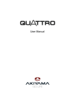
3. CONSTRUCTION
[a] EXTERIOR
[8]
[13]
[12]
[1]
[7]
[2]
[9]
[11]
[3]
[6]
[5]
[4]
[10]
(Front)
[1] Cleaning Water Outlet (20A)
[2] Neutralizer Vent (25A)
[3] Cleaning Water Vent (25A)
[4] Water Tank (Left)
Holds cleaning water in normal
dispensing mode and sanitizing water
in reverse dispense mode.
[5] Water Tank (Right)
Holds sanitizing water in normal
dispensing mode and cleaning water
in reverse dispense mode.
[6] Salt Chute Door
Open to add in salt.
[7] Operation Panel
Indicates the state of operation. See
“[e] OPERATION PANEL”.
[15]
[14]
(Rear)
[8] Sanitizing Water Vent (25A)
[9] Sanitizing Water Outlet (20A)
[10] Adjustable Legs
Keep the unit level and stable.
[11] Earth Wire
Ensure proper earth connection to
prevent electric shock.
[12] Power Cord (with L-shaped plug)
[13] Grommet
Receives the cable from the operation
box (option).
[16]
Front
(Bottom)
[14] Drain Outlet (G3/4 female)
[15] Tank Drain Outlet (G1/2 female)
[16] Water Inlet (Rc1/2 female)
13
[b] INTERIOR
[10]
[1]
[2]
[9]
[3]
[4]
[8]
[5]
[6]
[7]
[1] Power Switch (Earth Leakage Circuit Breaker)
Turns on and off the power supply.
[2] Control Panel (B)
ROX-60SA-E only. Provided with buttons and display for setting cell functions. See “[f]
CONTROL PANEL (A) (B)”.
[3] Water Softener
Softens tap water.
[4] Salt Water Tank
Dilutes salt to make salt water.
[5] Neutralizer
Neutralizes sanitizing water pH.
[6] Neutralizer Inlet
Open to add in neutralizing agent.
[7] Water Softener Timer
Sets the present time and regeneration time. See “[g] WATER SOFTENER TIMER”.
[8] Control Panel (A)
Provided with buttons and display for setting cell functions. See “[f] CONTROL
PANEL (A) (B)”.
[9] Water Sampling Tap
Sample water to check water hardness.
[10] Door
Open/close to evacuate the salt water pump and add in neutralizing agent.
14
[c] MECHANISM
[]
[3]
[4]
[9]
[2]
[0]
[2]
[8]
[] bulb location
[4]
[5]
[3] Flow switching valve interior
[3]
[6]
Cleaning
water
[7]
Sanitizing
water
[6] behind this
Impeller
rotates 90°
Cleaning
water
[5]
15
Sanitizing
water
[1] Control Box
Functions as the brain of the electrolyzer to control its operation (see "[d] CONTROL
BOX" for details).
[2] Water Valve
Supplies water from the water supply hose to the electrolytic cell or salt water tank.
[3] Flow Switching Valve
Operates every 12 hours to change the flow direction when the DC voltage to the
electrolytic cell reverses.
[4] Gear Motor
Rotates the impeller inside the flow switching valve.
[5] Microswitch (Location)
Senses the location of the flow switching valve. On the motor side.
[6] Microswitch (Direction)
Senses the direction of the flow switching valve. On the hose side.
[7] Flow Rate Sensor (Production)
Measures the flow rate to the electrolytic cell.
[8] Flow Rate Valve
Located between the water supply inlet and the electrolytic cell. Adjusts the rate of
water supply.
[9] Electrolytic Cell
Electrolyzes diluted salt water and produces sanitizing water and cleaning water.
Provided on the right side only for ROX-30SA-E.
[10] Salt Water Pump
Feeds a fixed amount of concentrated salt water (electrolyte) into the electrolytic cell.
[11] Thermistor
Senses the water temperature to prevent excessive available chlorine concentration
in low temperature conditions.
[12] Relief Valve
Operates when water delivery pipe pressure exceeds 0.3MPa and releases water
into the water tank to prevent water hammer.
[13] Pressure Switch
Detects water delivery pipe pressure and switches on/off.
[14] Flow Rate Switch (Water Delivery)
Detects water delivery pipe flow rate and switches on/off.
[15] Overflow Pipe
Keeps the salt water tank from leaking. Turn to the left to remove. Also functions as a
drain pipe.
[16] Overflow Hose
Prevents salt water from flowing out of the entire salt water tank in case the overflow
pipe clogs, by leaking salt water from a single spot (bottom panel mesh near
neutralizer).
16
[d] CONTROL BOX
[28]
[26]
[29]
[25]
[24]
[2]
[27]
[22]
[23]
[21] Bipower Relay
Turns on/off the supply line of the DC power supply [electrolytic cell]. Coil voltage
12VDC, contact current 10A.
[22] CB Relay
Changes the polarity of the voltage on the electrolytic cell. Coil voltage 12VDC,
contact current 30A.
[23] Current Sensor
Measures the current of the electrolytic cell.
[24] Noise Absorber
Noise absorbing board provided with a surge absorber.
[25] DC Power Supply (Main Control Board)
DC power supply to drive the DC electrical components. Output voltage 5V.
[26] Main Control Board
Functions as the brain of the controls to command inputs. Common between ROX30SA-E and ROX-60SA-E with model identification by provision of CN37 connector
(ROX-30SA-E: provided, ROX-60SA-E: not provided). Replacement of the main
control board for ROX-30SA-E will require reconnection of the CN37 connector to the
new board.
[27] DC Power Supply (Electrolytic Cell)
DC power supply for electrolysis in the electrolytic cell. Output voltage 12V.
[28] Earth Leakage Breaker
Shuts off the primary power supply in case of earth leakage or overcurrent.
[29] Control Panel
Allows various settings of the electrolytic cell functions. Provided on the right side
only for ROX-30SA-E.
17
[e] OPERATION PANEL
[1]
[2]
[10]
[3]
[9]
[8]
[7]
[4]
[5]
[6]
[1] Electrolyzed Water Lamp (blue = cleaning water, red = sanitizing water)
Indicates the type of water stored in the tank.
[2] Tank Level Lamp (green)
Indicates the water level for each tank in three steps. Electrolyzed water is not
available if this lamp is off.
[3] Flush (Reverse Dispense) Lamp (blue)
The sanitizing and cleaning water outlets are switched while this lamp is on. Check
with the electrolyzed water lamp.
[4] Replace Cell Lamp (red)
Flashes when the electrolytic cell needs to be replaced.
Replace cell lamp
Flash rapidly
100H
* Electrolysis will not stop
after 3000 hours.
Flash slowly
OFF
[5] Error Lamp (red)
Comes on or flashes in case of trouble.
[6] ON/OFF Switch
Starts and stops electrolyzing water.
[7] Operation Lamp (green)
Stays on while the unit is in operation. (ROX-60SA-E: Flashes when one unit is off.)
[8] Add Salt Lamp (red)
Comes on when the salt water tank is running out of salt.
[9] Reset Switch
Resets the add neutralizer lamp.
[10] Add Neutralizer Lamp (red)
Flashes when the neutralizer is getting empty.
18
[f] CONTROL PANEL (A) (B) [ROX-30SA-E: Control panel (A) only]
[1]
[2]
[3]
[7]
[4]
[6]
[5]
[1] Display
Indicates the cell run time, current, voltage, and error code in case of trouble.
[2] Display Lamp (red)
Indicates the displayed item.
[3] Display Select Button
For use by a trained operator and service personnel only.
[4] Flush Button
Press to flush the electrolyzed water circuit. The flush lamp on the operation panel
stays on while flushing.
[5] Flow Rate Lamp (red)
Indicates the current flow rate.
[6] Flow Rate Button
Adjusts the flow rate of both sanitizing water and cleaning water.
Reference: HI = for utensil, MID = for food, LO = for food
[7] Set/Reset Button
For use by a trained operator and service personnel only.
[g] WATER SOFTENER TIMER
[4]
[1]
1
2
9
3
7
6
5
24
2 3 4 5
6
4
1
7
8
20 21 22 23
8 9 10 11
12
10
19
[2]
11
18
12
14 15 16 17
13
[3]
19
[1] Contact Select Switch
Keep in the “AUTO” position.
[2] Time Indicator
Indicates the present time.
[3] Set Switch
Sets the water softener regeneration
time. Regeneration begins at the red
time zone.
[4] Frequency Select Switch
Set to your local frequency.
4. FUNCTIONS AND OPERATION
The control panel allows selections and settings of three different modes - normal,
adjustment and check. To select a mode, hold down the set/reset button and press the
display select button. The mode changes Nor. (normal) > Adj. (adjustment) > CHE. (check)
> Nor. (normal) every time the button is pressed.
[a] NORMAL MODE
The following menus are available in the normal (Nor.) mode.
No.
Menu
1 Cell run time (h)
2 Current (A)
3 Voltage (V)
Description
Total electrolytic cell run time at present.
Current flowing in electrolytic cell at present as measured by
current sensor.
Voltage provided on electrolytic cell at present as measured
by main control board.
[b] ADJUSTMENT MODE
The following menus are available in the adjustment (Adj.) mode.
Press the display select button to show the desired number in the display, press the flush
button to select the number, use the display select button and flush button as an up/down
button to adjust the setting, and press the set/reset button to store the changed setting or
press the display sellect button and flush button at the same time to cancel the adjustment.
No.
A1
A2
A3
A4
A5
Menu
Current (A)
Voltage (V)
Total flow rate (L/min)
Combination
Portion control time (min)
Cleaning water dispensing
A6
time for hand washing (s)
Sanitizing water dispensing
A7
time for hand washing (s)
Cell run time/reversal time
A8
reset
A9 Initial flash time (s)
A10 Cell replacement time (h)
A11 Cell reversal time (h)
Continuous dispensing
A12
protection time (min)
A13 Single nozzle
Factory default
Lo: 10, Std: 10, Hi: 10
N/A
Lo: 3.0, Std: 4.0, Hi: 6.0
N/A
N/A
Adjustable range/increments
5.0 to 13.0/0.1 (wt=25°C)
Skip (fixed at 12VDC)
2.0 to 8.0/0.1
Skip
Skip
N/A
Skip
N/A
Skip
N/A
3000
12
Display present run time, then
hold down set/reset button
(10s) to reset
Skip (Std, 0 to 20/1)
1500 to 9000/100
0.033 (check), 1 to 150/1
N/A
Skip
N/A
Skip
N/A
20
No.
Menu
Factory default
Water temperature correction
A14
4
factor
Flow rate adjustment factor,
A15
0.3
operation time factor
A16 Skip
N/A
Flow rate correction value
A17
0
(L/min)
Water softener regeneration 6 (ROX-30SA-E)
A18
12 (ROX-60SA-E)
output cycle
Salt water supply factor,
A19
0.3
feedback
A21 Raw water conductivity
100
Salt water supply factor, initial
A22
5
non-electrolysis time (s)
A23 Salt water supply factor
5
Salt water supply factor,
A25 stroke subtraction after
N/A
reaching set point (times/s)
A26 Reset
N/A
A27 Flow rate valve open/closed N/A
Current sensor type (20A or
A28
20
30A)
Sanitizing water neutralizing
A29
20
volume (x 1000L)
Adjustable range/increments
0 to 8/1
0.1 to 2.0/0.1
Skip
-0.5 to 0.5/0.1
0.1 to 20/0.1 (x 1000L)
3.0 to 10.5/0.5
Skip
Skip
0 to 75/5 (initial stroke)
Skip
Display "rSEt", then hold down
set/reset button (10s) to reset
Display current status
20, 30
15 to 50/1
* Basically do NOT adjust the menus in gray.
* See "5. WATER SOFTENER" for button operations.
[c] CHECK MODE
The following menus are available for in the check (CHE.) mode.
Press the display select button to show the desired number in the display, press the flush
button to select the number, and press the display sellect button and flush button at the
same time to complete.
No.
C1 Inputs
C2 Inputs
C3 Outputs
Menu
Remarks
Right side only, see details below
Right side only, see details below
Right side only, see details below
Amount of concentrated salt
water supply, max. 720 shots/min
Total flow rate in one cell
Thermistor sensing temperature
C4 EH pump stroke (spm)
C5 Total flow rate (L/min)
C6 Water temperature (°C)
21
No.
Menu
C7 Set current at present water temperature (A)
C8 Corrected current (A)
C9
C10
C11
C12
C13
C14
C15
C16
C17
C18
C19
C20
C21
C22
C23
C24
C25
C26
C27
C28
C29
C30
C31
C32
C33
C34
C35
C36
C37
C38
C39
C40
Elapsed cell reversal time (min)
Water flow after regeneration output (x 1000L)
Last error number
Cell run time at last error
Cell reversal time at last error
Current at last error
Voltage at last error
Total flow rate at last error
Salt water pump stroke at last error (spm)
Water temperature at last error (°C)
Set current at water temperature at last error (A)
Corrected current at last error (A)
Second from last error number
Cell run time at second from last error
Cell reversal time at second from last error
Current at second from last error
Voltage at second from last error
Total flow rate at second from last error
Salt water pump stroke at second from last error
(spm)
Water temperature at second from last error (°C)
Set current at water temperature at second from
last error (A)
Corrected current at second from last error (A)
Third from last error number
Cell run time at third from last error
Cell reversal time at third from last error
Current at third from last error
Voltage at third from last error
Total flow rate at third from last error
Salt water pump stroke at third from last error (spm)
Water temperature at third from last error (°C)
Set current at water temperature at third from last
error (A)
Corrected current at third from last error (A)
C41 Model configulation
C42 Control board version
Sanitizing water neutralizing volume after
C43
regeneration (x 1000L)
22
Remarks
Current after correcting water
temperature variations
Current after correcting current
sensor variations
ROX-30SA-E: 30
ROX-60SA-E (A side): 60-1
ROX-60SA-E (B side): 60-2
ON: on
OFF: off
ON/OFF
S2
(remote
controller)
Unused
ON: on
OFF: off
Unused
Unused
23
Contact open
Combination other than above
Unknown
Contact open
Contact open
ROX-30SA-E
Unused
Contact open
ON: closed
(fully closed)
OFF: open
(not fully closed)
ROX-60SA-E
Model 2
Contact closed
Contact open
Model 3
Unused
Model ON: closed
Master or (master)
slave
OFF: open
(slave)
Unused
Unused
Model 2 ON: closed
(*A)
OFF: open
ON: closed
OFF: open
Unused
Model
Fully
closed
signal
ON: closed
(on)
OFF: open
(off)
Salt water
tank lower
FS
ON: closed
(full)
OFF: open
(not full)
ON: closed
Regeneration (regeneration)
signal
OFF: open
(preparation)
Location
MS
Regeneration ON: closed (accept)
accept
OFF: open (reject)
(24H timer)
ON: closed
(full)
OFF: open
(not full)
A. Model identification (Models - 3)
Unused
Unused
Model 3
(*A)
Unused
Salt water
tank upper
FS
Unused
ON: closed
(fully open)
OFF: open
(not fully open)
Unused
closed
Test port ON:
OFF: open
Unused
ON: closed
OFF: open
Unused
Model (*A)
Fully
open
signal
Unused
Reset S2
(remote
controller)
C1 (Inputs) Display
ON: closed
Direction (on)
MS
OFF: open
(off)
Unused
Left tank
high
lower FS
Unused
Right tank
high
upper FS
24
ON: closed
(full)
OFF: open
(not full)
ON: closed
Left
pressure S (low)
open
(left tank) OFF:
(high)
ON: closed
Left flow S (high)
(left tank) OFF: open
(low)
Unused
Display 2 ON: no
(*B)
OFF: yes
Reset S ON: on
(operation OFF: off
panel)
Unused
øB. Whether operation panel (display ) on body is connected with remote controller (display 2) or not.
ON: on
OFF: off
Left tank ON: closed (full)
mid FS OFF: open (not full)
Down S
ON: on
OFF: off
Unused
ON: on
OFF: off
Unused
ON: closed
Right tank (full)
mid FS OFF: open
(not full)
ON: closed
(full)
OFF: open
(not full)
Up S
Right tank
high
lower FS
Unused
Unused
Set S
Unused
Left tank ON: closed
(full)
high
upper FS OFF: open
(not full)
ON: closed
(low)
OFF: open
(high)
ON: closed
(full)
OFF: open
(not full)
Left tank ON: closed
(full)
low
upper FS OFF: open
(not full)
ON: closed
(full)
OFF: open
(not full)
ON: closed
Right tank (full)
low
OFF: open
upper FS (not full)
Right
pressure S
(right tank)
Right tank
low
lower FS
Left tank
low
lower FS
ON: closed
Right flow S (high)
(right tank) OFF: open
(low)
ON: closed
(full)
OFF: open
(not full)
Unused
ON/OFF
S
ON: on
(operation OFF: off
panel)
Unused
Unused
C2 (Inputs) Display
Flow rate S ON: on
OFF: off
Unused
Unused
Unused
Unused
Unused
Unused
25
ON
OFF
INT INT 2
ON
OFF
Open
(raising flow
rate)
Brake
ON
ON
(turning off flow
rate valve)
ON: H
OFF: L
Closed
Stop
OFF
OFF
(keeping flow
rate valve off)
Step ON: Tr on
motor 2 OFF: Tr off
Fan ON: Tr on (on)
motor OFF: Tr off (off)
ON: closed
(open)
OFF: open
(closed)
(reducing flow
rate)
INT 2
(*C)
Unused
Regeneration ON: closed (yes)
request
OFF: open (no)
ON: closed
DC power (on)
supply OFF: open
(off)
Left
shut-off
valve
ON: closed
(open)
OFF: open
(closed)
ON: closed
Right water (on)
pump
OFF: open
(off)
closed
Solenoid ON:
metering (on)
OFF: open
pump
(off)
øC. Flow rate valve outputs
ON: H
OFF: L
ON: Tr on
OFF: Tr off
ON: Tr on
OFF: Tr off
Step ON: Tr on
motor OFF: Tr off
Step
motor 3
DC
switching
negative
ON: closed
Salt water (open)
valve
OFF: open
(closed)
DC
switching ON: Tr on
positive OFF: Tr off
Water
valve
Unused
INT (*C)
ON: closed
(open)
OFF: open
(closed)
Unused
Unused
Unused
Right
shut-off
valve
Unused
Unused
Unused
C3 (Outputs) Display
ON: closed
Left water (on)
pump
OFF: open
(off)
Step
ON: Tr on
motor 4 OFF: Tr off
5. WATER SOFTENER
[a] DISCHARGE VOLUME
The discharge volume of the water softener is adjustable. Check your local water hardness
and adjust the volume to the proper level. The water softener requires regeneration
(to remove calcium and magnesium attached on the ion exchange resin inside) after
discharging a specific volume of soft water.
Note: The discharge volume is factory adjusted to 6 tons for ROX-30SA-E and 12 tons for
ROX-60SA-E.
For ROX-60SA-E, the adjustment must be made on the control panel (A).
1)Turn on the power switch (earth leakage circuit breaker).
2)Press and hold the set/reset button. When “Nor.” (normal) appears on the display,
press the display select button. “Adj.” (adjust) appears on the display.
3)Release the set/reset button. “A1” (current) appears on the display.
Note:If other than “A1” appears, press the set/reset button to have “A1” on the display.
4)Press the display select button until “A18” (water softener discharge volume) appears
on the display.
Note:If “A18” is passed on, press the set/reset button to go back to “A1”.
5)Press the flush button. The display shows “6” for ROX-30SA-E and “12” for ROX60SA-E. Now the discharge volume is adjustable.
6)Use the UP/DOWN button (UP: display select button, DOWN: flush button) to adjust
the discharge volume. The selected volume flashes on the display.
7)Press the set/reset button to set the volume. The display stops flashing and shows
“A18”.
8)Press and hold the set/reset button, and press the display select button. “CHE.” (check)
appears on the display.
9)Press and hold the set/reset button, and press the display select button. “Nor.” (normal)
appears on the display.
10) Release the set/reset button to complete the adjustment.
26
To adjust the “A18” setting, refer to the following table and calculation formula.
Water Hardness and Regeneration Cycle
Water
hardness
(mg/L)
30
40
50
60
70
80
90
100
110
120
130
140
150
160
170
180
190
200
210
220
230
240
250
260
270
280
290
300
Discharge volume (t)
ROX-30SA-E
ROX-60SA-E
[flow rate 3L/min]
[flow rate 6L/min]
10.0
20.0
7.5
15.0
6.0
12.0
5.0
10.0
4.3
8.6
3.8
7.5
3.3
6.7
3.0
6.0
2.7
5.5
2.5
5.0
2.3
4.6
2.1
4.3
2.0
4.0
1.9
3.8
1.8
3.5
1.7
3.3
1.6
3.2
1.5
3.0
1.4
2.9
1.4
2.7
1.3
2.6
1.3
2.5
1.2
2.4
1.2
2.3
1.1
2.2
1.1
2.1
1.0
2.1
1.0
2.0
* Factory default in gray
Regeneration cycle (h)
ROX-30SA-E
ROX-60SA-E
27.8
20.8
16.7
13.9
11.9
10.4
9.3
8.3
7.6
6.9
6.4
6.0
5.6
5.2
4.9
4.6
4.4
4.2
4.0
3.8
3.6
3.5
3.3
3.2
3.1
3.0
2.9
2.8
27.8
20.8
16.7
13.9
11.9
10.4
9.3
8.3
7.6
6.9
6.4
6.0
5.6
5.2
4.9
4.6
4.4
4.2
4.0
3.8
3.6
3.5
3.3
3.2
3.1
3.0
2.9
2.8
Example
If the tap water hardness is 150 mg/L (ppm) (ROX-30SA-E):
(Default discharge volume) x {(Standard hardness) / (Local hardness)} = Local discharge
volume
6.0 x { 50 / 150 } = 2.0
Therefore, the discharge volume must be adjusted to 2.0 tons.
27
[b] REGENERATION PROCESS
No.
Process
1
2
3
4
Backwash
Recharge / displace
Rinse
Refill
Reference: factory default
(external input)
5 min
60 min
5 min
3 min
*The processes 2 and 3 can be skipped at the time of installation. When the process
number stops flashing and stays on, press the manual switch to proceed to the next
process.
*There is no problem with the equipment operation even if the time in the display differs
from the present time.
*Do not change the program of the water softener or press the switches other than the
manual switch.
Process number
Time
Manual switch
28
Water
supply
1.
Backwash
(5 min)
Reverse water flow to
soak resign beads.
Water
supply
2.
Recharge / displace
Feed salt water to wash
resin beads with:
tank full of salt +
salt water valve open for
6 min (ROX-30SA-E) or
0 min (ROX-60SA-E).
(60 min)
Water
supply
3.
Rinse
(5 min)
Rinse off salt water.
Check Valve
4.
Water
supply
Refill
(3 min)
Salt Water
Tank
Water
Softener
Open check valve.
Feed water into salt
water tank.
29
6. NEUTRALIZER
*The add neutralizer lamp flashes after a specific time estimated from sanitizing water
overflow. The lamp may not start flashing when the neutralizer actually gets empty.
*The neutralizing agent is limestone consisting of almost pure calcium carbonate (CaCO3).
Based on experimental data, approximately 300g of limestone is consumed per ton of
sanitizing water overflow.
2HCl + CaCO3 → CaCl2 + H2O + CO2
*The add neutralizer lamp starts flashing rapidly after 20 tons of sanitizing water overflow
(factory default), then the unit automatically stops production (To restart the unit, hold
down the reset switch on the operation panel for more than 5 seconds, then press the
ON/OFF switch). To encourage supply of the neutralizing agent, the add neutralizer lamp
starts flashing slowly after 14 tons of overflow, that is, 70% of 20 tons.
Flash rapidly
20 tons
4 tons
30%
70%
Flash slowly
OFF
0 ton
Sanitizing water overflow and add neutralizer lamp
*After adding the neutralizing agent (up to the "MAX" line
of the neutralizer), be sure to hold down the reset switch
on the operation panel for more than 5 seconds to reset
the count of sanitizing water overflow.
MAX
MAX
MIN
30
7. WATER CIRCUIT
31
. Normal operation (no polarity change)
Water supply
Cleaning water
Sanitizing water
2. Normal operation (polarity change (automatically every 2h))
Water supply
Polarity change is made
separately for left and right cells.
Change valve is switched at the
same time.
Operational check of change
valve is easier with polarity
change every 2 min (adjust
0.033 by “A”).
Cleaning water
Sanitizing water
3. Flush
Water supply
Change valve switches left
and right circuits with no
polarity change.
Sanitizing water
Cleaning water
32
33
20
ホ
8. WIRING DIAGRAM
III. SERVICE INFORMATION
1. MAINTENANCE/INSPECTION
Check the following items during maintenance or inspection in normal condition. If any
abnormality or defect is found, repair, replace or adjust it properly.
No.
1
2
3
4
5
6
7
Inspection
Item
Check
Sanitizing water pH
Within specified range?
Cleaning water pH
Within specified range?
Available chlorine
Within specified range?
concentration (sanitizing water)
Flow rate (sanitizing/cleaning Within specified range?
water)
Ambient temperature
Within specified range?
Water supply temperature
Within specified range?
Water supply pressure
Within specified range?
8 Replace cell lamp
Flashing or stays on?
9 Earth Leakage Circuit Breaker Trips when test button is
pressed?
10 Salt water tank
No dirt buildup?
No salt deposit at bottom?
11 Filter
Not clogged with dirt?
12 Earth wire
Not damaged or loose?
13 Attachment plug
Securely plugged in?
Not hot?
14 Exterior
Clean?
15 Water circuit
No water leak?
16 Water softener
Water softened?
Working properly?
Set to regenerate while
unit is out of service?
Proper salt level?
17 Cartridge filter
Pressure difference within
specified range?
18 Water outlets
Not blocked?
Working properly?
19 Labels
Firmly attached?
34
Remedy
Check with pH test paper.
Check with pH test paper.
Check with o-Tolidine.
Check with beaker.
Check with thermometer.
Check with thermometer.
Check with water pressure
gauge.
Visually check.
Check.
Visually check.
Visually check.
Visually check.
Visually check.
Visually check.
Check.
Visually check.
Visually check.
Check water sample.
Check.
Check.
Check.
Visually check.
Visually check.
Check.
Visually check.
2. ERROR CODES
Error
No.
Control panel
display
Error
lamp
Flash
Problem
Operation
Flow rate stayed below Production stops Remove cause
1.5L/min for 10 sec
after water valve and press ON/
with water valve on
turns off twe times OFF switch
Fully closed valve, set
Automatically
flow rate, or fully open Production
reset even in
valve not detectable
continues
operation if cause
for 12 sec
is removed
Flow rate stayed above Production stops Remove cause
1.5L/min for 10 sec
after water valve and press ON/
with water valve off
turns on twe times OFF switch
Low water
E11 Error no.
Flow rate
valve
Alternate
between normal
E12
display and error
no.
Water
shutoff
E14 Error no.
Flash
Salt water
tank supply
Alternate
between normal
E31
display and error
no.
Flash
Salt water tank did not
Production
fill up after 30 min of
continues
water supply
Current stayed below
0.5A for 2 sec
On
DC relay
contact
E53 Error no.
Flash
Flow
switching
valve
E61 Error no.
Flash
Thermistor
Alternate
between normal
E74
display and error
no.
On
Salt water
tank float
switch
Alternate
between normal
E81
display and error
no.
On
Reset
Production
stops after relay
switches three
times
Remove cause
and press ON/
OFF switch
Remove cause
and press ON/
OFF switch
Remove cause
Switching did not
Production stops and press ON/
complete within 30 sec
OFF switch
Production
Automatically
continues as 5°
Open circuit (-30°C) or
reset even in
C (open circuit)
short circuit (60°C)
operation if cause
or 30°C (short
is removed
circuit)
Automatically
Upper switch on, lower Production
reset even in
switch off
continues
operation if cause
is removed
35
Error
Water tank
high float
switch
Water tank
low float
switch
(pumping
protection)
Control panel
display
Alternate
between normal
E82
display and error
no.
No.
Alternate
between normal
E85
display and error
no.
Alternate
Water
between normal
softener
E91
display and error
regeneration
no.
Alternate
Pumping
between normal
E92
function
display and error
no.
Model
setting
EE1 Error no.
Control
board
EF0 Error no.
Control
board
Alternate
between normal
EF1
display and error
no.
Salt water
level
—
(Add salt lamp
on)
Replace cell
(Replace cell
— lamp flashes
slowly)
Replace cell
(Replace cell
— lamp flashes
rapidly)
Add
neutralizer
(Add neutralizer
— lamp flashes
slowly)
Add
neutralizer
(Add neutralizer
— lamp flashes
rapidly)
Error
lamp
Problem
Operation
Reset
On
Production
Upper switch on, lower
continues (for at
switch off
least 3 min)
Automatically
reset even in
operation if cause
is removed
On
Upper switch on, lower Production
switch off
continues
Automatically
reset even in
operation if cause
is removed
On
No regeneration signal,
Production
regeneration did not
continues
complete within 90 min
Automatically
reset even in
operation if cause
is removed
Flash
Off
Flow rate switch turned
Pumping stops
off with water pump on
after restarted
or turned on with water
three times
pump off
Model setting or
communication
Production and
connector in bad or
pumping stop
wrong connection,
slave circuit open
Remove cause
and press ON/
OFF switch
Remove cause
and press ON/
OFF switch
Remove cause
and press ON/
OFF switch
Production
Automatically
continues (stops reset even in
Off
Check SUM error
with power on),
operation if cause
pumping available is removed
Salt water pump
Add salt and
Add salt stayed at 720 spm for Production stops press ON/OFF
90 sec
switch
Replace cell,
select "A8", hold
Cell run time exceeded
Replace
Production
down set/reset
2900 hours (factory
cell
continues
button for 10 sec,
default)
and turn on/off
power switch
Replace cell,
select "A8", hold
Cell run time exceeded
Replace
Production
down set/reset
3000 hours (factory
button for 10 sec,
cell
continues
default)
and turn on/off
power switch
Add neutralizer,
Sanitizing water
hold down reset
Add
neutralization volume Production
switch for 5 sec,
neutralizer exceeded 14 tons
continues
and press ON/
(factory default)
OFF switch
Add neutralizer,
Sanitizing water
hold down reset
Add
neutralization volume
Production stops switch for 5 sec,
neutralizer exceeded 20 tons
and press ON/
(factory default)
OFF switch
On
EEPROM error
36
Production and
pumping stop
3. SERVICE DIAGNOSIS
Error
E11
(low water)
Problem
Check
Possible cause
Flow rate sensor detected flow Water supply line Water failure
rate below 1.5L/min for 10 sec Electrolyzed
Blocked
with water valve on
water outlet
Joint hose
Crushed or bent
Scaled
Filter
Clogged
Water valve
Clogged
Connector in bad
contact
Defective
Flow rate sensor Clogged
Connector in bad
contact
Defective
E12
Fully closed valve, set flow
Flow rate valve Connector in bad
(flow rate valve) rate, or fully open valve was
contact
not detectable for 12 sec when
Defective
flow rate changed
E14
Flow rate sensor detected flow Water valve
Defective
(water shutoff) rate above 1.5L/min for 10 sec
Clogged
with water valve off
E31
Salt water tank did not fill up
Water valve
Clogged
(salt water tank after 30 min of water supply
Connector in bad
supply)
contact
Defective
Float switch
Jammed
Defective
Overflow pipe
Improperly
attached
Damaged
E53
Electrolytic current stayed
Current sensor Defective
(DC relay
below 0.5A for 2 sec
Signal line open
contact)
circuit
DC power supply Defective
Cell wiring
Red and black
wires swapped
Open circuit
E61
Switching did not complete
Gear motor
Defective
(flow switching within 30 sec
Location
Defective
valve)
microswitch
Direction
Defective
microswitch
E74
Open circuit (-30°C) or short
Thermistor
Defective
(thermistor) circuit (60°C) was detected
E81
Upper float switch turned on
Float switch
Defective
(salt water tank and lower float switch turned
float switch) off during production
E82
Upper high float switch (top)
Float switch
Defective
(water tank high turned on and lower high float
float switch) switch (2nd from top) turned off
37
Remedy
Recover water supply
Unblock
Correct
Replace
Unclog
Unclog
Correct
Repair or replace
Unclog
Correct
Repair or replace
Correct
Repair or replace
Repair or replace
Unclog
Unclog
Correct
Repair or replace
Unjam
Repair or replace
Correct
Repair or replace
Repair or replace
Correct
Repair or replace
Correct
Repair or replace
Repair or replace
Repair or replace
Repair or replace
Repair or replace
Repair or replace
Repair or replace
Error
E85
(water pump
float switch)
Problem
Check
Upper low float switch (bottom) Float switch
turned on and lower low float
switch (2nd from bottom)
turned off
E91
Water softener regeneration
Water softener
(water softener did not complete within 90 min
regeneration)
E92
Flow rate switch turned off with Water pump
(pumping)
water pump on or turned on
with water pump off
Flow rate switch
Pressure switch
Drain valve
EE1
Model setting or control board Model setting
(model
connector in bad or wrong
connector on
recognition) connection
control board
Control board
wiring
EF0
EEPROM error
Control board
(control board)
EF1
Check SUM error
Control board
(control board)
38
Possible cause
Defective
Remedy
Repair or replace
Defective
Repair or replace
Vapor lock
Defective
Defective
Defective
Closed
Bad contact
Correct
Repair or replace
Repair or replace
Repair or replace
Switch to pumping
Correct
Open circuit
Repair or replace
Defective
Repair or replace
Defective
Repair or replace
4. REMOVAL AND REPLACEMENT OF COMPONENTS
Control Box
Electrolytic
Cell
[f]
[b]
[e]
Front Cover
[a]
Water
Softener
Salt Water
Tank
[d]
[c]
Transformer
Neutralizer
[a] FRONT COVER
Loosen the two screws on the top of
the front cover, and remove the two
screws at the bottom (red arrows).
Remove the front cover, and hook it
inside the door.
The operation panel becomes easily
accessible during service and
maintenance.
39
[b] ELECTROLYTIC CELL
Drain the hose at the bottom of the
cell.
Disconnect the wiring connectors.
Disconnect the sanitizing and cleaning
water hoses by pinching the end of
the connector and pulling off the hose.
Remove the upper wiring screws
from the cell terminal block.
Remove the screws at the four
corners of the sheet metal cell base.
Pull out the cell together with the base.
40
Remove the bracket (three screws).
Use plumber’s pliers to disconnect the
four hoses at the cell inlets and outlets.
Slide out the cell toward you.
41
[c] NEUTRALIZER
Remove the bracket (two screws).
Remove the cap from the end of the
drain hose, and drain the neutralizer.
If the drain hose is clogged with
limestone, use a hand oil pump or
the like to drain the hose.
Remove the quick clamp from the
neutralizer inlet and outlet.
Pull out the inlet and outlet pipes, and
lift the neutralizer off the unit.
42
[d] SALT WATER TANK
Uncover the salt water tank (six
screws).
Remove the tie and disconnect the
hose from the right rear of the salt
water tank (be sure to reconnect
after service and maintenance).
Turn the overflow pipe to the left to
disconnect, and drain concentrated
salt water.
Remove the four screws from the
sheet metal part of the unit.
Remove the quick clamp from the
bottom of the salt water tank, and
disconnect the drain pipe.
Disconnect the float switch wiring
connectors, and lift the salt water
tank off the unit.
43
[e] WATER SOFTENER (* Remove neutralizer and salt water tank first)
Depressurize the water circuit by
turning on the power with water
supply off. Use plumber’s pliers to
disconnect the pipes from the water
softener.
Disconnect the metal band, and
remove the water softener.
Use a rubber belt wrench to turn
and disconnect the resin cylinder.
Replace the resin.
44
[f] CONTROL BOX
Remove the upper wiring screws
from the cell terminal block.
Disconnect the wiring connectors.
Remove the two screws from the
unit rail.
Slide out the control box toward you
(heavy, be careful).
Turn the control box upside down,
and place it on a table.
Remove the cover.
45
5. INSTALLATION AND SAFETY PRECAUTIONS
[a] VENT LINES
The vent lines must be installed to prevent health problems or damage to surrounding
equipment (e.g. corrosion, tank burst with increasing internal pressure) caused by
hydrogen gas or chlorine gas generated from electrolyzed water.
CAUTION
Run the sanitizing water, cleaning water, and neutralizer vent lines separately to
the outside.
Cover the vent pipe ends with nets or bored end caps to protect against insects.
IMPORTANT
1. The sanitizing water, cleaning water, and neutralizer vent lines must be
separate pipes.
2. The vent pipes must be sloped upward all the way to the ends without going
up and down.
3. Do not use any metal weather cover at the vent pipe ends.
4. The vent pipes must be sized at least 30A.
5. Protect the vent pipe functions from snowfall, freeze-up, and flying objects.
Make the vent connections as shown below.
Note: The plumbing materials must be prepared on site.
Upward bend allowed
Min. 500mm
Min. 1000mm
Make 2mm bores as many
Use 30A tees to help
as possible in 30A end caps horizontal gas diffusion and
for protection against insects drain rainwater downward.
Min. 4m from ground, min. 1m from windows/openings
Example
No ups and downs
1/50
1/50
1/50
To neutralizer vent
Outdoor
To cleaning
water vent
Indoor
GL
46
To
sanitizing
water vent
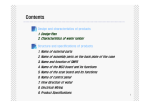
[b] NEUTRALIZER
The neutralizer must be supplied with a proper level of neutralizing agent (limestone).
Otherwise, sanitizing water overflow runs out without being neutralized and may corrode
the drain pipe or attack concrete.
[c] SALT
Do not leave spilled salt around the unit. The door and sheet metal parts inside the unit
may corrode.
47
IV. AUTOMATIC DISPENSING VALVE VDW-2PB-E (OPTION)
The automatic dispensing valve VDW-2PB-E is a compact and stylish sensor operated
valve to automatically dispense sanitizing water and cleaning water produced by the water
electrolyzer. It can be installed on either the counter or the wall.
1. DIMENSIONS/SPECIFICATIONS
48
2. CONSTRUCTION
[a] VALVE UNIT
(Front)
[1]
[5]
[1]
[6]
(Rear)
[6]
[2]
[3]
[7]
[7]
[4]
[1] Dispense Sensor
Functions in the same way as the dispense/stop button. Senses a hand or object to
start and stop dispensing electrolyzed water without using the dispense/stop button.
The detection range is 50 mm.
[2] Electrolyzed Water Outlet
Dispenses sanitizing water or cleaning water.
[3] Outlet Lamp
Provided inside the electrolyzed water outlet. Illuminates in red while sanitizing water
is being dispensed and in blue while cleaning water is being dispensed.
[4] AC Adapter
1 phase 90 - 264V
[5] Operation Panel
Provided with operation buttons, display, and lamps.
[6] Quick Fitting
Connected to the water delivery lines.
[7] Mounting Bracket
Fixes the product to the wall.
49
[b] OPERATION PANEL
[1]
[8]
[2]
[9]
[3]
[10]
[4]
[11]
[5]
[10]
[6]
[7]
[12]
[13]
[1] Auto Lamp (orange)
Comes on in the automatic dispensing mode.
[2] Cleaning Lamp (blue)
Flashes while cleaning water is being dispensed. Stays off in standby for the
automatic dispensing mode and stays on in standby for the timer dispensing or
continuous dispensing mode.
[3] Display
Indicates the dispensing time and data settings.
[4] Select Lamp (blue, red)
Indicates the type of electrolyzed water available by pressing the dispense/stop
button in the timer dispensing or continuous dispensing mode.
Also indicates the type of electrolyzed water being dispensed.
Cleaning water = left, blue
Sanitizing water = right, red
[5] Valve Reversal Mark
Comes on while the valve operation is reversed (with “U9” set to “1”). See “4. [a]
STANDARD SETTINGS”.
[6] Sanitizing Lamp (red)
Flashes while sanitizing water is being dispensed. Stays off in standby for the
automatic dispensing mode and stays on in standby for the timer dispensing or
continuous dispensing mode.
[7] Mix Lamp (green) [option required]
Flashes while mixed water is being dispensed. Stays off in standby for the automatic
dispensing mode and stays on in standby for the timer dispensing or continuous
dispensing mode.
[8] Timer Lamp (orange)
Comes on or goes off when the mode select button is pressed.
Timer dispensing mode = ON
Continuous dispensing mode = OFF
[9] Mode Select Button
Switches between the timer dispensing and continuous dispensing modes.
[10] Shift Button
Shifts to another dispensing mode. See “3. DISPENSING MODES AND
OPERATION”.
50
[11] Dispense/Stop Button
Starts and stops dispensing electrolyzed water.
[12] Data Set Button
Press to check or adjust the dispensing mode settings.
[13] Tap Water Lamp (orange) [option required]
Flashes while tap water is being dispensed. Stays off in standby for the automatic
dispensing mode and stays on in standby for the timer dispensing or continuous
dispensing mode.
3. DISPENSING MODES AND OPERATION
Automatic dispensing mode
Display/
functions
Timer dispensing mode or continuous dispensing mode
Cleaning water
Sanitizing water
Shift
button
Shift
button
Dispense sanitizing water and
Dispense sanitizing water and cleaning water for the
cleaning water automatically in the preset time or continuously.
preset order for the preset time.
Dispensing order
Dispensing time (timer dispensing mode only)
Set items
Dispensing time
Dispense/ Start/stop automatic dispensing
Start/stop dispensing
Start/stop dispensing
stop button
cleaning water
sanitizing water
Dispense Start/stop automatic dispensing
Start/stop dispensing
Start/stop dispensing
sensor (left)
cleaning water
cleaning water
Dispense Start/stop automatic dispensing
Start/stop dispensing
Start/stop dispensing
sensor (right)
sanitizing water
sanitizing water
Timer/
Timer dispensing only
Timer/continuous dispensing Timer/continuous dispensing
continuous
1)Press the dispense/stop button, 1)Press the dispense/stop button, or hold up a hand over
or hold up a hand over the
the dispense sensor.
dispense sensor.
The selected water is dispensed. The cleaning/sanitizing
The selected water is dispensed lamp flashes, and the outlet lamp also illuminates. In the
according to the timer setting.
portion dispensing mode, after the preset dispensing
The cleaning/sanitizing lamp
time has elapsed, the lamps go off and dispensing
flashes, and the outlet lamp
stops.
also illuminates. After the preset
dispensing time has elapsed,
Operation
the lamps go off and dispensing
stops.
51
Timer dispensing mode or continuous dispensing mode
Cleaning water
Sanitizing water
2)To stop dispensing in the middle 2)To stop dispensing, press the dispense/stop button, or
of the program, press the
hold up a hand over the dispense sensor. The cleaning/
dispense/stop button, or hold
sanitizing lamp and outlet lamp go off, and dispensing
up a hand over the dispense
stops.
sensor.
If sanitizing water is dispensed last, cleaning water is automatically dispensed for 1.5 seconds
with the select lamps flashing.
Automatic dispensing mode
Operation
Flushing
process
4. ADJUSTMENT
[a] STANDARD SETTINGS
To enter the adjustment mode, hold down the data set button for 3 seconds. "USEr"
appears in the display.
To return to the normal mode, hold down the data set button for 3 seconds. "oooo" appears
in the display.
* < > = optional setting
Code
Item
Description
Default
U1 1st water & dispensing time in 0: None, 1: Cleaning, 2: Sanitizing,
1: Cleaning
automatic dispensing mode
<3: Mixed>, <4: Tap>
15 sec
1 to 200 sec (in 1 sec steps)
U2 2nd water & dispensing time in 0: None, 1: Cleaning, 2: Sanitizing,
2: Sanitizing
automatic dispensing mode
<3: Mixed>, <4: Tap>
15 sec
1 to 200 sec (in 1 sec steps)
U3 3rd water & dispensing time in 0: None, 1: Cleaning, 2: Sanitizing,
0: None
automatic dispensing mode
<3: Mixed>, <4: Tap>
15 sec
1 to 200 sec (in 1 sec steps)
U4 4th water & dispensing time in 0: None, 1: Cleaning, 2: Sanitizing,
0: None
automatic dispensing mode
<3: Mixed>, <4: Tap>
15 sec
1 to 200 sec (in 1 sec steps)
U5 5th water & dispensing time in 0: None, 1: Cleaning, 2: Sanitizing,
0: None
automatic dispensing mode
<3: Mixed>, <4: Tap>
15 sec
1 to 200 sec (in 1 sec steps)
U6 Cleaning water dispensing
1 to 200 sec (in 1 sec steps)
15 sec
time in timer dispensing mode
U7 Sanitizing water dispensing
1 to 200 sec (in 1 sec steps)
15 sec
time in timer dispensing mode
U8 Neutralizing (cleaning) water 0 to 10 sec (in 0.5 sec steps)
1.5 sec
dispensing time
52
Code
Item
U9 Valve reversal (*1)
Description
0: L-cleaning, R-sanitizing
1: L-sanitizing, R-cleaning
0 to 10 sec (in 0.5 sec steps)
U10 Undetectable time after
switching sensor ON/OFF (*2)
U11 Left/right sensor distinction (*3) 0: Yes
1: No
U12 Countdown in automatic
0: Individual
dispensing mode (*4)
1: Total
U13 Cleaning water outlet lamp
0 to 100% (in 1% steps)
color & brightness (*5)
U14 Sanitizing water outlet lamp
color & brightness (*6)
0 to 100% (in 1% steps)
U50 Initialization (*7)
*1
*2
*3
*4
*5
*6
*7
Default
0: L-cleaning,
R-sanitizing
1.5 sec
0: Yes
0: Individual
Blue: 90%
Red: 0%
Green: 0%
Blue: 0%
Red: 90%
Green: 0%
0: None
0: None
1: Initialize
Open/close the solenoid valve opposite to the detecting sensor.
Set the sensor response speed.
Make the left and right sensors indistinctive.
Select the automatic dispensing mode countdown between individual dispensing time
for each type of water or total dispensing time.
Adjust the color and brightness of the outlet lamp for cleaning water.
Adjust the color and brightness of the outlet lamp for sanitizing water.
Reset all the settings to the default settings.
[b] OPTIONAL SETTINGS (OPTION REQUIRED)
To adjust the settings “U15” and “U16”, select “Yes” in the service setting “d2”.
To adjust the settings “U17”, “U18”, and “U19”, select “Yes” in the service setting “d3”.
Code
Item
Description
U15 Mixed water dispensing time in 1 to 200 sec (in 1 sec steps)
portion dispensing mode
U16 Mixed water outlet lamp color 0 to 100% (in 1% steps)
& brightness (*8)
U17 Tap water dispensing time in 1 to 200 sec (in 1 sec steps)
portion dispensing mode
U18 Tap water outlet lamp color & 0 to 100% (in 1% steps)
brightness (*9)
U19 Tap water addition (*10)
0: No
1: Yes
*8 Adjust the color and brightness of the outlet lamp for mixed water.
53
Default
15 sec
Blue: 0%
Red: 0%
Green: 90%
15 sec
Blue: 40%
Red: 40%
Green: 0%
0: No
*9 Adjust the color and brightness of the outlet lamp for tap water.
*10 Add tap water to sanitizing water, cleaning water, and mixed water.
[c] SERVICE SETTINGS
To enter the adjustment mode, hold down the data set button and mode select button for 4
seconds. "dSEr" appears in the display.
To exit the adjustment mode and return to the normal mode, hold down the data set button
and mode select button for 4 seconds. "oooo" appears in the display.
Code
Item
d1 Software version
d2 Mixed water mode
d3
d4
d5
d6
d7
d8
d9
d10
d11
d12
d13
d14
d15
d16
d17
d18
Description
Version number of software used
0: No
1: Yes
Tap water mode
0: No
1: Yes
Neutralizing water type
1: Cleaning 2: Mixed 3: Tap
Sensor function
0: ON
1: OFF
LED lamp flashing speed
0: Low
1: High
LED lamp flashing time
0.1 to 10 sec (in 0.1 sec steps)
Portion dispensing mode
0: Stop
(action with sensor reactivated) 1: Extend
Continuous dispensing mode 0 to 1,000 sec (in 10 sec steps)
protection time
Automatic dispensing mode
0 to 99,990,000 times (in 1 time
activation counter
steps) (*1)
Cleaning water mode activation 0 to 99,990,000 times (in 1 time
counter
steps) (*1)
Sanitizing water mode
0 to 99,990,000 times (in 1 time
activation counter
steps) (*1)
Mixed water mode activation
0 to 99,990,000 times (in 1 time
counter
steps) (*1)
Tap water mode activation
0 to 99,990,000 times (in 1 time
counter
steps) (*1)
Cleaning water sensor
0 to 99,990,000 times (in 1 time
activation counter (*2)
steps) (*1)
Sanitizing water sensor
0 to 99,990,000 times (in 1 time
activation counter (*2)
steps) (*1)
Dispense/stop button activation 0 to 99,990,000 times (in 1 time
counter (*2)
steps) (*1)
Cleaning water valve activation 0 to 5,000,000 times (in 1 time
counter
steps) (*1)
54
Default
N/A
0: No
0: No
1: Cleaning
0: ON
0: Low
1 sec
0: Stop
300 sec
0 time
0 time
0 time
0 time
0 time
0 time
0 time
0 time
0 time
Code
Item
Description
Default
d19 Sanitizing water valve activation 0 to 5,000,000 times (in 1 time
0 time
counter
steps) (*1)
d20 Tap water valve activation
0 to 5,000,000 times (in 1 time
0 time
counter
steps) (*1)
d21 Control board activation
0 sec to 10 years (in 0.1 sec steps) 0 sec
counter
d22 Demo mode
0: Normal
0: Normal
1: Demo
d23 Demo mode interval
0 to 200 sec (in 1 sec steps)
60 sec
d24 1st dispensing in demo mode <1st digit: water type>
1: Cleaning
1: Cleaning 2: Sanitizing
3: Mixed
4: Tap
<2nd to 4th digits: time>
10 sec
0 to 200 sec (in 1 sec steps)
d25 2nd dispensing in demo mode <1st digit: water type>
2: Sanitizing
1: Cleaning 2: Sanitizing
3: Mixed
4: Tap
<2nd to 4th digits: time>
10 sec
0 to 200 sec (in 1 sec steps)
d26 3rd dispensing in demo mode <1st digit: water type>
0
1: Cleaning 2: Sanitizing
3: Mixed
4: Tap
<2nd to 4th digits: time>
10 sec
0 to 200 sec (in 1 sec steps)
d27 4th dispensing in demo mode <1st digit: water type>
0
1: Cleaning 2: Sanitizing
3: Mixed
4: Tap
<2nd to 4th digits: time>
10 sec
0 to 200 sec (in 1 sec steps)
d28 5th dispensing in demo mode <1st digit: water type>
0
1: Cleaning 2: Sanitizing
3: Mixed
4: Tap
<2nd to 4th digits: time>
10 sec
0 to 200 sec (in 1 sec steps)
d29 Initialization
0: No
0: No
1: Yes (*3)
*1 To reset the settings “d10” to “d20” to 0, hold down the two shift buttons for 3 seconds.
*2 The number of sensor/button activations from the off state.
*3 Selecting “1” and exiting the adjustment mode will reset all the settings except the
activation counters to the factory defaults.
55
V. REMOTE CONTROLLER ROX-RCUA (OPTION)
1. DIMENSIONS/SPECIFICATIONS
56
2. INSTALLATION INSTRUCTIONS
57