1
16.
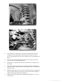
Attach the shock to the axle with the original shock hardware. Torque bolts to
20 ft-lbs. Go back and tighten the upper shock stem nut until the stem bushings
begin to swell. Install the thin jam nut on the stem and tighten it against the first
nut.
17.
Reattach the drag link to the pitman arm with the original castellated nut.
Torque the nut to 60 ft-lbs. Align the cotter pin hole with the slots in the nut and
install the cotter pin. Never loosen the nut to align the cotter pin, only tighten.
If the original cotter pin is damaged, replace it with a new one.
18.
Install the wheels and torque the lug nuts to the manufacturer’s specs. See vehicle owner’s manual.
19.
Remove the jack stands and lower the vehicle to the ground.
20.
Bounce the front of the vehicle to settle the suspension.
21.
Attach the sway bar links to the sway bar with the original hardware/bushings.
Tighten nuts until the bushings begin to swell.
22.
Reconnect the front track bar to the axle mount with the original hardware.
Torque bolt to 50 ft-lbs. Note: To aid in aligning the track bar hole have an assistant turn the steering wheel to shift the trackbar in the correct direction.
23.
Torque the lower control arm bolts to 85 ft-lbs.
24.
Check all hardware for proper torque.
»»R
ear Installation
Step 4 Note
The upper factory shock bolts
are prone to corrosion. Take care
removing the bolts, they can break
easily.
Step 6 Note
Slightly loosening the driver’s side
u-bolts will allow the axle to lower
from the spring with less restriction.
J3310, J3311 Installation - pg. 4
1.
Block the front wheels for safety.
2.
Raise the rear of the vehicle with a hydraulic jack and support with jack stands
at the frame rails just ahead of the leaf spring hanger.
3.
Remove the wheels.
4.
Support the rear axle with a hydraulic jack. Remove the shocks. Save all shock
hardware.
Complete the following one side at a time, starting with the passenger’s side.
5.
With the rear axle well supported with a hydraulic jack, remove the leaf spring
u-bolts. The sway bar link bracket will be free with the removal of the outer ubolt.
6.
Lower the axle from the spring.
7.
Remove the factory bend-over style leaf spring clamps. These will not be reused.
8.
Place C-clamps on each side of the leaf spring center pin to hold the leaf pack
together. Remove the leaf spring center pin and then release the C-clamps. This
will allow the leaf pack to come apart. Take note each leafs' position and orientation (front to rear).
9.
The leaf lengths get shorter as they go from the top leaf in a pyramid shape (Figure 4). Insert the supplied add-a-leaf in the appropriate position to form a pyramid shape. Using the C-clamps on each side of the center pin hole, compress
the leafs together while aligning the new center pin through all of leaf center pin
holes (from the bottom up). With the pack completely compressed together with
the clamps, fasten the center pin with the provided nut. Torque nut to 20 ft-lbs.
Cut off any access center pin. Do not use the center pin to compress the pack
together.
10.
Remove the C-clamps from the leaf pack and ensure the individual leafs are all
inline with each other. Install the provided bend-over style clamps on the leaf
pack (Figure 5). Install one clamp on each side of the center pin about 12” from
the center pin. Bend the ends of the clamps over to secure them to the spring.