1
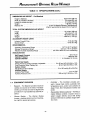
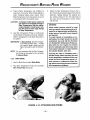
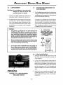
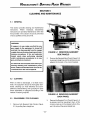
OPERATING PRECAUTIONS
GENERAL PRECAUTIONS
.
Federal Law restricts this device to sale by or on order of a physician.
.
Infant radiant warmers should be used only by properly trained personnel as directed by an appropriately
qualified physician aware of currently known hazards and benefits.
.
The functional checkout procedure should be performed before each use and after disassembly for
cleaning, servicing or maintenance. Refer to qualified service personnel if the unit does not perform as
specified.
.
The Cart/Bassinet End and Side panels cannot be used for pushing or pulling the Cart/Bassinet and or
Warmer.
.
Do not leave the infant unattended in the Cart/Bassinet when the side panels orthefront panel arefolded
down.
.
To avoid overheating or underheating, skin temperature must be continuously monitored and controlled
either manually or automatically. Rectal temperature should never be used to control skin temperature.
.
To avoid overheating or underheating when operating in manual mode, observe the infant constantly and
monitor the temperature using the temperature probe supplied with the equipment or another electronic
thermometer.
.
The skin temperature sensing probe must be in direct contact with the skin to provide accurate monitoring of the infant’s skin temperature. Failure to maintain direct skin contact can result in overheating and
possible burning. Check infant’s condition at least every fifteen minutes for correct Sensor attachment,
reddened skin areas, and proper skin temperature.
.
The skin temperature sensing probe should be placed at least 1.5 inches from any transcutaneous monitor (TcPOz or TcPCOz) probe to prevent false temperature indications. The skin temperature probe
should not be placed on an area previously used by a TcPOz or TcPC02 probe.
.
To avoid overheating the skin, the location of the skin temperature probe must be such that the skin
around the Sensor is in direct line with the radiation from the warmer. Do not place anything between the
radiant warmer and the infant that will interfere with the radiation from the warmer.
.
Radiant warming increases insensible water loss. Appropriate measures to maintain proper fluid balance should be considered.
.
For effective heating, make sure the Warmer Module is positioned on the center axis and locked with its
detent.
.
This Warmer is intended for use with the Cart/Bassinet. If the Warmer is used to warm the mother immediately after delivery, all warnings and instructions should be followed with particular regard to the
heater-to-mattress distance and skin probe location. Avoid placement of objects near the mother which
can absorb heat and become hot to the touch.
.
Compressed gas cylinders, such as oxygen cylinders, can become hazardous projectiles if the gas is
released rapidly due to damage or other causes. Cylinders must be securely fastened.
.
To avoid overheating the Warmer, do not place objects (equipment, blankets, clothing or sterile packs) on
top of the Warmer.
COPYRIGHT@3 1998, HILL-ROM AIR-SHIELDS, INC.
OPERATING PRECAUTIONS (Continued)
l
Avoid placement of objects between the infant and the Warmer Module that can block heat transfer or
absorb heat. These objects may be heated directly by the heater and can cause skin burns.
a
Temperature uniformity (per IEC 601-2-21) across the mattress surface may not be maintained when
the Bassinet is tilted in the 5- and 1 O-degree positions.
l
During calibration, inspect the secondary reflector directly under the warmer heater element for particles.
If particles are present, replace the heater element. The life expectancy of the heater element is 1000
hours of operation.
0
Evidence that the safety certification of the ACCESSORY has been performed in accordance with the
appropriate IEC 601-l and/or IEC 601-l-l harmonized national standard.
RESUSCITATION PRECAUTIONS
A one-way valve is installed at the Patient Outlet connection. This valve opens when pressure in the
hose delivering gas to the patient falls below -4 cm H20. Its purpose is to allow patient inspiration in the
unlikely event of failure of the gas supply.
A humidifier, when used, must be placed between the Patient Outlet connection and the patient circuit.
DO NOT PLACE A HUMIDIFIER IN THE SUPPLY LINE.
Humidifier must have low series flow resistance and not be placed between exhalation valve and patient
airway.
Gas going to the patient should not be super-saturated as evidenced by excessive condensation in the
tubing. Condensation droplets on the inner walls of the tubing are normal.
Periodic blood gas measurements should be made to ensure proper levels of ventilation.
Always confirm the airway pressure relief valve setting before patient use.
Confirm that the oxygen/air blender control of the Blended Gas Supply Module is correctly set prior to
use.
Confirm that the patient circuit contains all the parts needed prior to use.
Ensure that the patient breathing circuit connections are secure and free of obstructions.
The Aux Outlet circuit does not provide adjustable pressure limiting.
Auxiliary Gas Supply Pressure is internally limited to 160 cm HzO. Always use a patient resuscitation
circuit that includes appropriate pressure relief.
Always monitor Airway Pressure and/or provide appropriate pressure relief during infant resuscitation.
Confirm that the oxygen supply is turned off and that the equipment is disconnected from the oxygen
supply when performing cleaning and maintenance procedures; a fire and explosion hazard exists when
performing cleaning and/or maintenance procedures in an oxygen-enriched environment.
Gas supplies (02 and Air) should always be clean and dry. Water/Trap Filters should be used in the supply lines if necessary.
All hoses should be securely fastened to fittings. Hand-tighten to avoid damage to fittings.
Gas supplies should be maintained at 40 to 75 psi.
Flow restrictions (e.g., flowmeter, valve, etc.) must not be placed in the supply line.
If a compressor is used as the air source, steps should be taken to filter and dehumidify the room air
before introducing it into the Gas Supply Module.
_ ii _
OPERATING PRECAUTIONS (Continued)
ELECTRICAL PRECAUTIONS
a
An electrical shock hazard exists within the Warmer Module and Controller. Any substitution of components within the Controller or Warmer Module may impair the intrinsic safety of the unit. Service should
be performed by qualified personnel.
0
Connect the power cord only to a properly grounded receptacle that is approved for hospital use and of
the correct voltage. DO NOT USE EXTENSION CORDS.
l
Use only with power cords supplied with the Warmer.
EXPLOSION PRECAUTIONS
l
Do not use in the presence of flammable anesthetics.
0
Confirm that the oxygen supply is turned off and that the equipment is disconnected from the oxygen
supply when performing cleaning and maintenance procedures; a fire and explosion hazard exists when
performing cleaning and/or maintenance procedures in an oxygen-enriched environment.
OXYGEN PRECAUTIONS
l
Improper use of supplemental oxygen may be associated with serious side effects including blindness,
brain damage, and death. The risks vary with each infant. The method, the concentration, and the duration of oxygen administration should be prescribed by the attending physician.
.
If it is necessary to administer oxygen in an emergency, the attending physician should be notified immediately.
NOTE: See the current edition of “Guidelines for Perinatal Care”of the American Academy of Pediatrics/The
American College of Obstetricians and Gynecologists.
.
The oxygen concentration inspired by an infant does not predictably determine the partial pressure of
oxygen (PO,) in the blood. When deemed advisable by the attending physician, blood PO2 should be
measured by accepted clinical techniques.
.
Oxygen flow rates cannot be used as an accurate indication of oxygen concentrations. Oxygen concentrations should be measured with acalibrated oxygen analyzer at intervals directed by the attending physician.
.
Keep matches and all other sources of ignition out of the room in which the Warmer is located and keep
spark-producing equipment or any sources of ignition out of the Bassinet. Wood, textiles, oils, and other
combustibles are easily ignited and burn with great intensity in air enriched with oxygen.
.
Although oxygen compatible materials are used in the oxygen delivery system, special care must be taken when high pressure oxygen such as found in a medical oxygen cylinder is used. Violent ignition of oil,
grease, greasy substances, small particles of dust, dirt or other particulate contaminants (even small
particles of metal), can occur in the presence of high pressure oxygen if their ignition temperature is
reached. An instantaneous increase in temperature can occur due to friction, particle acceleration, or
adiabatic compression, if the oxygen cylinder valve is opened too rapidly. SERIOUS INJURY MAY RESULT! Always observe the following precautions:
-
Oil, grease, greasy substances, dust, dirt and other particulate contaminants must be kept away
from oxygen regulators, cylinder valves, tubing and all other oxygen equipment.
- III -
OPERATING PRECAUTIONS (Continued)
-
Always open oxygen cylinder shut-off valves very slowly and carefully.
-
On high pressure oxygen cylinders use only pressure regulators or reducing valves approved for
oxygen service. Do not use oxygen pressure regulators or reducing valves for air or gases other
than oxygen as they may be hazardous. Operate such devices in strict accordance with the
manufacturer’s recommendations.
-
When new or replacement oxygen cylinders are to be installed, they should have their outlet ports
cleared by cracking the cylinder valve momentarily before attachment to the equipment.
LOW FLOW MICROBLENDER WARNINGS
l
If either the air or oxygen gas source pressure is reduced or increased creating a pressure
differential of 30 psi, the microblender alarm will sound. This condition significantly alters the
FiO2 and flow output from the microblender.
Always operate the low flow microblender with clean/dry medical grade gases.
.
Air inlet water filters are recommended for use with the low flow microblender.
.
The level of oxygen and the partial pressure of oxygen within the patient’s blood
should be monitored.
l
- iv -
(Pa02)
TABLE OF DEFINITIONS AND SYMBOLS
NOTE, IMPORTANT, PRECAUTION, CAUTION, AND WARNING
NOTE: A Note is inserted in text to point outprocedures or conditions which may otherwise be misinterpreted
or overlooked. A Note may also be used to clarify apparent/y contradictory or confusing situations.
IMPORTANT
Similar to a Note but used when greater emphasis is required.
PRECAUTION: A Precaution is supplementalinformation
equipment.
CAUTION:
to assist the user in the safe and effective use of the
A Caution is inserted in text to call attention to a procedure which, if not followed exactly,
can lead to damage or destruction of the equipment.
WARNING: A Warning is inserted in text to call attention to dangerous or hazardous conditions
inherent to the operation, cleaning, and maintenance of the equipment which may result In personal injury or death of the operator or patient.
SYMBOLS
/
o-
\
Attention: consult
accompanying documents.
-
Examination Light
08
’ I ’
Type B equipment with an F-type
isolated (floating) applied part.
Examination Light Switch
A
Mode Control Key
8
Danger! High Voltage!
Temperature Override Mode
Key
Keypad Lock Key
Disposable Suction Bottle
00
Reusable Suction Bottle
I
Set Temperature Keys
Power On/Off Switch
Celsius/Fahrenheit Selection
Key
Patient
Heater Element
Silence/Reset Key
Suction Line Filter
Procedural Silence Indicator
w@
Load Symbol
-V-
Apgar Timer Keys
TABLE OF CONTENTS
PAGE
SECTION
1
.........................................................
1 GENERALINFORMATION..
1
1.1 INTRODUCTION.. ......................................................................
1
.........................................................................
1.2 DESCRIPTION
.......................................................................
1
1.3 SPECIFICATIONS
3
1.4 EQUIPMENTPROVIDED ................................................................
...................................................
4
1.5 FACTORY INSTALLED ACCESSORIES
.................... 4
1.6 FIELD INSTALLED ACCESSORIES (Refer to Section 6 for Part Numbers)
6
2 INSTALLATION
.....................................................................
6
2.1 UNPACKING ...........................................................................
..........................................................6
2.2 ASSEMBLY (Refer to Figure 2.1)
2.3 ASSEMBLY OF CART/BASSINET .........................................................6
........................................................
8
3 FUNCTIONAL DESCRIPTION
8
3.1 GENERAL ..............................................................................
8
............................................................
3.2 FUNCTIONALDESCRIPTION
8
..............................................................
3.2.1 WARMERMODULE..
8
3.2.2 CART/BASSINET ..................................................................
3.2.3 CONTROLLER ....................................................................8
3.2.4 BLENDER MODULE (OPTIONAL) .................................................... 8
3.2.5 RESUSCITATION MODULE (OPTIONAL) ............................................. 8
3.2.6 GAS SUPPLY MODULE (OPTIONAL) ............................................... 12
13
3.2.7 ALARMS .........................................................................
3.2.8 APGARTIMER ...................................................................13
......................................................................
14
4 OPERATION
..........................................
14
4.1 CONTROLS, INDICATORS AND CONNECTORS
4.2 OPERATIONAL CHECKOUT PROCEDURE - CONTROLLER ............................... 24
25
4.3 MECHANICALCHECKOUT .............................................................
............
27
4.4 RESUSCITATION EQUIPMENT PRE-USE CHECKOUT AND SETUP (OPTIONAL)
27
4.4.1 SUPPLYPRESSURE ..............................................................
.............
27
4.4.2 BLENDED GAS SUPPLY PRE-USE CHECKOUT AND SETUP (OPTIONAL)
4.4.3 RESUSCITATION MODULE PRE-USE CHECKOUT AND SETUP (OPTIONAL) .......... 28
29
4.5 CONTROLLEROPERATION ............................................................
29
...............................................................
4.5.1 PRE-WARMMODE
29
4.5.2 MANUALMODE ..................................................................
30
4.5.3 BABYMODE .....................................................................
31
4.5.4 EXAMINATION LIGHT .............................................................
32
4.6 CART/BASSINET ......................................................................
32
4.7 DOCKlNGANDUNDOCKlNGTHECART/BASSlNET
......................................
32
.................................................................
4.8 X-RAYPROCEDURES
33
5 CLEANINGANDMAINTENANCE ...................................................
33
5.1 GENERAL .............................................................................
33
............................................................................
5.2 CLEANING
33
5.3 DISASSEMBLYFORCLEANING .........................................................
34
5.4 CLEANINGPROCEDURES .............................................................
34
5.4.1 CLEANING AGENTS.. ............................................................
34
5.4.2 PAINTEDSURFACES .............................................................
54.3 CLEAR PLASTIC AND ACRYLIC SURFACES ........................................ 34
-vi-
TABLE OF CONTENTS (continued)
SECTION
5.4.4 METAL SURFACES ...............................................................
5.4.5 WOODEN SURFACES ............................................................
5.4.6 SKIN TEMPERATURE PROBE (REUSABLE) .........................................
5.5 STERILIZATION .......................................................................
5.6 REASSEMBLY AFTER CLEANING ......................................................
5.7 CALIBRATION .........................................................................
5.8 TROUBLESHOOTING ..................................................................
6 PARTS LIST .......................................................................
6.1 GENERAL .............................................................................
-vii-
PAGE
34
34
35
35
35
35
35
37
37
RESUSCITAIREB BIRTHING ROOM WARMER
SECTION 1
GENERAL INFORMATION
please contact your Hill-Rom Air-Shields’ representative for further information.
1 .l INTRODUCTION
This manual provides instructions for installation,
use, operator maintenance and troubleshooting of
the equipment. Hill-Rom Air-Shields cannot be responsible for the performance of the equipment if
the user does not operate the equipment in accordance with the instructions, fails to follow the maintenance recommendations in Section 5 of this
manual or effects any repairs with unauthorized
components. Calibration and repair should be performed only by qualified service personnel. Service
manuals are available from Hill-Rom Air-Shields.
1.2 DESCRIPTION
The ResuscitaireB Birthing Room Warmer is designed specifically for birthing room use. The Resuscitaire8 Birthing Room Warmer consists of a
detachable Cart/Bassinet, Warmer, and a Controller module which provides heat control, monitoring
of skin temperature and Apgar timing. The Resuscitaire8 Birthing Room Warmer also includes an
optional resuscitation package with suction and
oxygen delivery. Other options include a reserve
gas supply and blender.
This manual should be read, thoroughly understood, and be readily accessible to all personnel
who will be working with the equipment. The manual
should be stored with the equipment when not in
use. If there is anything you do not understand,
1.3 SPECIFICATIONS
Specifications for the
ResoscitaireB Birthing
Room Warmer are provided in Table 1 .l . All specifications are subject to change without notice.
-l-
RESUSCITAIREGI BIRTHING ROOM WARMER
TABLE 1.1 SPECIFICATIONS
POWER REQUIREMENTS ...........................................
12OV, 60 Hz, 750W
OVERLOAD PROTECTION ..................................... Dual 12A Circuit Breakers
CHASSIS LEAKAGE CURRENT
....................................... Less than 300 uA
EXAMINATION LIGHT. .............................. >lOO Foot Candles (0.12 lumens/cm:z)
ALARMS
High Temperature
................................ Activates if Skin Temperature Probe is
attached and the skin temperature
sensor reaches 39.0 “C. Resets at 38.5 “(3.
Check Patient ................................ Activates in Manual Mode after 10 minutes.
Remains on with audible alarm every
30 seconds for 5 minutes;
totalling 15 minutes. Then the heater is turned Off.
Apgar Timer ............................................Activates at the l-, 5-and lominute Apgar Time intervals.
Power Fail ................................................... Activates when there is a
loss of power.
Probe.. .......................................
Activates if Skin Temperature Probe fails
(open or short).
SystemFail ..........................................
Indicates system failure; refer unit
to service immediately.
BabyTemp ..............................................
Activates if Baby Temperature
fluctuates 1 “C above or below set poirit.
Electrical Module Audio Alarms ....................... Tone Frequency: 1.2 KHz maximum
Three-stage sound level: 15 seconcls
low, 15 seconds medium, then high.
Blender Module Pneumatic Audio Alarm ..................................Vibrating Reed.
DISPLAYS
Skin Temperature Display
Accuracy.. .................................
f 0.2 “C for 31 “C to 37 “C (88 “F to 98.6 “F)
Resolution .............................................................0.1 “C (0.5 “F)
Apgar Timer Display
Range ...............................................
Resolution .................................................................
Accuracy .............................................................
MANUAL HEAT CONTROL
0 to 59 minutes, 0 to 59 seconcls
lsecond
Of0.5second
..................................Adjustable in 10% increments
from zero to full power (100 %#)
DATA PORT .....................................................
2400 Bits/second fixed
Baud Rate. RS232C Compatible
DIMENSIONS AND WEIGHT-FREE STANDING WARMER
Height ...........................................................
74 inches (188 cm)
Width (side to side) ................................................
28 inches (102 cm)
Depth (front to back) .................................................40 inches (89 cm)
Weight (without tanks) ................................................. 170 Ibs (77 kg)
Warmer Head Rotation (right and left) .......................................
90 Degrees
-2-
RESUSCITAIREGO BIRTHING ROOM WARMER
TABLE 1 .I SPECIFICATIONS (Cont.)
DIMENSIONS AND WEIGHT - Cart/Bassinet
38.5 inches (98 cm)
Height to Mattress ................................................
Width (to outside of bumper) ......................................... 24 inches (61 cm)
Length (to outside bumper) .......................................... 31 inches (79 cm)
Weight ........................................................... c 160 Ibs (c73 Kg)
5 and 10 degrees Reverse Trendelenburg.
MattressTilt .................................
Infant’s head should be toward front of warmer.
TOTAL SYSTEM DIMENSIONS AND WEIGHT
..74inches(188cm)
Height .........................................................
28inches (71 cm)
Width .............................................................
48inches(122cm)
Length ..........................................................
..c320Ibs(c152Kg )
Weight ........................................................
ACCESSORY WEIGHT LIMITS
5 Ibs (2.2 Kg)
Infusion Pump/IV Pole ...................................................
Monitor Shelf .......................................................... 10 Ibs (4.5 Kg)
ENVIRONMENTAL
.................................. 18 “C to 30 “C ambfent
Operating Temperature Range
Storage Temperature Range ..................................- 20 “C to +45 “C ambient
Relative Humidity Operating Range .................. 5% RH to 95% RH, non-condensrng
RESUSCITATION
Wall Supply Pressure ...................................................
Cylinder Pressure .....................................................
Cylinder Diameter ............................................
40 to 75 psi
2900 psi max
4-5 inches( 1 O-l 2 cm)
Patient Gas Supply
0 to 50 cm Hz0 (4.9 kPa) + 10%
Airway Pressure Limiting Operator-Adjustable
.. . 60 cm Hz0 (5.9 kPa) 2 10%
Fixed Pressure Relief, Factory Set .....................................
Suction Circuit
0 to 150 mmHg (0 to 20 kPa)
Adjustable Suction Intensity ................................
Auxiliary Supply
0 to 15 LPM
Auxiliary Flow Range .....................................................
Auxiliary Pressure Limit .................................... 160 cm Hz0 (16 kPa) -c 10%
.
1.4 EQUIPMENT PROVIDED
.
.
Bassinet - The Bassinet provides maximum
visibility and access to the infant. The Bassinet tilts up in the rear to 5 and 10 degrees and
provides for X-ray Cassette tray (optional) insertion.
.
Warmer Module - The Warmer Module
houses a heating element and an Examination Light for special procedures.
-3-
Controller - The Controller provides prewarm, manual heat control, automatic skin
temperature servo-control and contains an
Apgar Timer, Skin Temperature monitor and
probe.
Resuscitation Module (optional) -The Resuscitation Module contains a suction circuit, a
patient oxygen delivery circuit with airway
pressure relief and an auxiliary oxygen delivery circuit.
RESUSCITAIR~ BIRTHING ROOM WARMER
1.5 FACTORY INSTALLED OPTIONS
.
Resuscitation Module
.
Integrated Precision Blender
.
Gas Supply Module
1.6
FIELD INSTALLED ACCESSORIES
(Refer to Section 6 for Part Numbers)
.
X-ray Cassette Tray
.
Air Hose Assembly
.
Oxygen Hose Assembly
.
Monitor Shelf
-
02 Pipeline and Cylinder
.
I.V. Pole
-
Oz/Air Pipeline and Cylinder
.
Drawer Organizer
-4-
RESUSCITAIREB BIRTHING ROOM WARMER
DRAWER
LOCK
PASS-THROUGH
DRAWER
CASTER LOCK
WARMER MODULE
CONTROLLER
MONITOR SHELF
/
3c.
iT TILT
MtwiANISM
\
BLENDED GAS
SUPPLY MODULE
RESUSCITATION
GAS SUPPLY MODULE
X-RAY TRAY 4
WALL 02/AIR
GAS HOSES
- GAS TANKS
(NOT SUPPLIED)
SUCTION BOTTLE
CAiTER LOCK
PASS-THROUGH DRAWER
FACTORY INSTALLED OPTIONS AND
FIELD INSTALLED ACCESSORIES
FIGURE 1 .I EQUIPMENT PROVIDED WITH
-5-
RESUSCITAIREGQ BIRTHING ROOM WARMER
SECTION 2
INSTALLATION
2.1 UNPACKING
7.
SLOWLY LOWER THE WARMER (7) onto the
Upper Post. Tighten the upper screws and
install the remaining four 10 - 32 x 3/8 inch
screws (6).
8.
THREAD THE WARMER POWER CABLE
out through the Controller opening. Connect
the Power Cable (10) to connector J4 on the
Controller (3).
9.
REMOUNTTHE CONTROLLER on the Upper
Post.
10
MOUNT THE BACK COVER (1) on the Upper
Column using the six 8
- 32 x 3/4 painted
screws (5).
11.
MOUNT THE HANDLE (12) on the Post using
the two 10 - 32 x 2.6 inch Phillips Head
Screws, No. 10 Lock Washers and Spacers
The ResuscitaireB Birthing Room Warmer is
shipped in two cartons. One carton contains the following assemblies:
.
Upper Post Assembly
.
Lower Post Assembly
.
Warmer Module Assembly
.
Post Handle
.
Any user installed Accessories that were ordered
The other carton contains the Cart/Bassinet.
2.2
ASSEMBLY OF THE WARMER
FER TO FIGURE 2.1)
(RE-
When removing the equipment from the carton, use
care not to scratch or otherwise damage unprotected surfaces; remove all packing material.
(13 1 (14 1 (15 ).
12. CONNECT THE LINE CORD to the Power
Connector on the rear of the Controller (refer to
Figure 4.2).
NOTE: If a Monitor Shelf is to be installed on the
unit, refer to the instructions provided with
the Monitor Shelf and install the weights
provided with these accessories in the bottom of the Lower Post.
1.
REMOVE THE CONTROLLER (3)
Upper Post (2).
13. SECURE THE LINE CORD to the Back Cover
(1) using the Cable Clamp (8) and 8 - 32 x 3/8
screw (9).
from the
CAUTION: Securing the Line Cord to the Back
Panel is required to prevent removal
of the Controller chassis with the ac
power applied.
CAUTION: Two persons of sufficient strength
are required when performing Steps
3 through 6.
2.
REST THE UPPER POST (2)
Lower Post opening.
3.
CONNECT THE SUCTION HOSE (4) to the
Suction Hose (11). Release the joined Suction
Hoses from the Neat Clip inside the Lower Column.
14. INSTALL ANY ACCESSORIES that were ordered using the installation instructions provided with the accessory.
on top of the
4.
MOUNT THE UPPER POST (2) on the Lower
Post using four 10 - 32 x 3/8 inch screws (16)
provided.
5.
INSTALL TWO 10 - 32 X 3/8 INCH SCREWS
(6) IN THE UPPER HOLES OF THE UPPER
POST. Do not tighten the screws.
6.
RAISE THE WARMER (7) above the open end
of the Upper Post (2) and insert the Power
Cable (10) into the open end of the column.
2.3
1.
2.
-6
ASSEMBLY OF THE CART/BASSINET
Refer to Paragraph 5.6, Step 4, and install the
Rear and Side Panels. Raise the Front Panel
from its storage slot and lock it in place.
ENGAGE THE CART/BASSINET TO THE
WARMER by pushing the Cart/Bassinet
straight onto the Warmer until it latches. Pull on
the Cart/Bassinet to ensure that it is latched
properly.
To disengage the Cart/Bassinet from the
Warmer, push and hold the release switch
(Figure 4.14) and pull the Cart/Bassinet away
from the Warmer.
RESUSCITAIREB BIRTHING ROOM WARMER
PARTS LIST
Screw, lo-32~3/8(QtylO) . ...99041 36
Screw, 10 - 32 x 2.6 (Qty 2) . . . . .99 045 30
Screw, 8 - 32 x 3/4 (Qty 6) . . . . .99 032 85
Screw, 8 -32 x 3/8 (Qty 1) . . . . . .99 031 38
No.iOLockWasher . . . . . . . . . . . . 9912416
Spacer (Qty 2) . . . . . . . . . . . . . . . . .99 124 61
..1772564
Cable Clamp
Post Handle . : : : : 1: : : : : : : : 1: : . .81 005 73
FIGURE 2.1 INSTALLATION
-7-
RESUSCITAIREB BIRTHING ROOM WARMER
SECTION 3
FUNCTIONAL DESCRIPTION
3.1 GENERAL
This section provides a functional description of the
equipment.
3.2 FUNCTIONAL DESCRIPTION
3.2.1 WARMER MODULE
full power. After 10 minutes of operation in the Manual Mode, a Chk Patient Alarm occurs.
Failure to acknowledge the Check Patient Alarm by
pressing the Silence/Reset Key within the next 5
minutes will cause the heater to be shut down.
The Apgar Timer displays the elapsed time and
sounds an audible dual tone to alert the operator
that 1, 5, and 10 minutes have elapsed since the
timer was activated.
The Warmer is controlled by a Controller which provides Pre-Warm Mode, Manual Mode heater control, or Baby Mode (automatic skin temperature
control). An Examination Light provides added illumination of the mattress area. A Warmer Head Pivot
permits the Warmer to be pivoted to either side for
X-ray procedures. In addition, when the Warmer is
pivoted, it can be powered and provide heat.
When operated in the Baby Mode, the Controller
utilizes a Skin Temperature Probe, connected between the Controller input and the infant, to automatically adjust the heater output of the Warmer
Module to maintain a digitally displayed preset Set
Temperature.
3.2.2 CART/BASSINET
The Bassinet is designed to provide maximum function and utility to aid in the care of the newborn. It is
detachable so that the infant can be transported to
the NICU, the general nursery or another area of the
hospital. The side and front panels may be folded
down to permit maximum access to the infant. The
mattress may be tilted up in the rear at a 0, 5- or
lo-degree angle. Openings are provided on each
side of the Bassinet for the insertion of the optional
X-ray Cassette Tray.
3.2.3 CONTROLLER
The Keypad Lock Key, when pressed, renders the
Up/Down Arrows and Select Mode Keys inactive or
active.
Also included is a Procedural Silence Timer to block
out Baby Temp audible Alarms during routine procedures.
3.2.4 BLENDER MODULE (OPTIONAL)
The Blender Module provides blended oxygen from
21% to 100% to the Patient Outlet on the Resuscitation Module.
3.2.5 RESUSCITATION MODULE (OPTIONAL)
At power-up, the microprocessor within the Controller performs a series of diagnostic tests to confirm the proper operation of the system. During this
time, all displays and indicators are lighted (except
Power Fail) and an audible tone is sounded.
The Resuscitation Module contains pneumatic circuitry necessary for infant resuscitation. Controls
and displays for the module are located above and
to the rear of the Bassinet.
The Resuscitation Module consists of the following
components:
PreWhen powered up, the system initializes in
Warm Mode, the Controller will start the heater at
100% power and maintain that setting forthree minutes, reduce to 60% for 12 minutes and then reduce
the heater power to 30%.
.
When operating the Controller in the Manual Mode,
the operator can adjust the heater power from 0 to
-8-
Suction - The Suction Circuit (reusable or
disposable) is driven by a gas powered venturi
actuated vacuum generator which provides a
negative pressure for suctioning the patient’s
airway. The suction pressure is indicated on
the Suction Gauge (Figure 3.1). Suction pres-
RESUSCITAIR~ BIRTHING ROOM WARMER
Switch. A fixed internal relief valve limits the
maximum suction level to 150 mmHg.
sure may be adjusted using the Suction Control or turned on and off using the On/Off
Extension Tube
Suction Catheter
Suction Catheter
I
I
‘Extension Tube
Disposable
Reusable
Note: Disposable bottle
has built-in filter
FIGURE 3.1 SUCTION FUNCTIONAL BLOCK DIAGRAM
-9-
RESUSCITAIR~ BIRTHING ROOM WARMER
FIGURE 3.2 RESUSCITATION MODULE WITH PATIENT GAS SUPPLY AND
AUXILIARY FLOW
.
.
Patient Gas Supply -
The Patient Gas Supply Circuit may be used to
provide continuous gas flow to the patient. Controls
are provided for Airway Pressure Relief (maximum pressure) and Flow Rate (LPM) (circuit flow
delivering 100% oxygen or blended gas). The adjustable Airway Pressure Relief Control is always
operative.
A fixed internal safety relief valve is also provided
and is also always operable. This valve provides redundant maximum pressure relief at 50 + 10 cm
Hz0 and also allows the patient to inspire room air in
the event of gas supply failure.
Auxiliary Flow
The Aux Flow circuit supplies 100% oxygen
through the Aux Flow (LPM) Control to the Aux
Outlet Connector. It is intended for oxygen enrichment of a manual bag resuscitator, for supplemental
delivery to the patient, the mother, or a second neonate, i.e., twins. The Aux Flow (LPM) Control adjusts the flow rate from 0 to 15 Ipm. An internal preset relief valve limits the AUX Outlet pressure to
160 cm HzO.
.
Airway Pressure
The Airway Pressure Gauge displays airway pressure when connected to patient circuits via external
connection.
WARNING: Breathing room air through the
2-way relief valve requires extra effort. This
condition, if it occurs, should be rectified as
soon as possible.
.
Patient Breathing and Supply Circuits
The patient breathing circuit used in conjunction
with the Resuscitation Module is illustrated in Figure
3.3. In addition, a patient supply circuit for Manual
Bagging (Figure 3.4) may also be used.
-10
RESUSCITAIREQXJ BIRTHING ROOM WARMER
l-CORRUGATED TUBING
5-EXHAUST PORT
2-EXHALATION VALVE HOUSING
6-PATIENT PORT
3-EXHALATION VALVE CAP
7-“T” FITTING
STEM
OF
ITEM
4
4-EXHALATION VALVE DIAPHRAGM
NOTE: EXHALATION VALVE DIAPHRAGM (ITEM 4)
MUST BE INSTALLED WITH DIAPHRAGM STEM
GAUGE
FIGURE 3.3 PATIENT BREATHING CIRCUIT FOR MANUAL VENTILATION
2-10 mm Corrugated Tubing
l-10/7.5 mm ID Adapter
3-15 mm/l0 mm Adapter
CONNECT BETWEEN PATIENT
OUTLET AND RESUSCITATION
FIGURE 3.4 PATIENT BREATHING CIRCUIT FOR MANUAL BAGGING
-ll-
RESUSCITAIR~ BIRTHING ROOM WARMER
I
3.2.6
GAS SUPPLY MODULE (Optional)
The Gas Supply Module includes an On/Off Switch
which controls the pipeline and cylinder gas supply
to the Resuscitation Module. An oxygen cylinder
Pressure Gauge is provided if the Resuscitation option is included. Oxygen and Air Pressure Gauges
are provided on units equipped with the Blender
Module.
FIGURE 3.5 GAS SUPPLY MODULE
-12-
/?EsuscimmD BIRTHING ROOM WARMER
3.2.7 ALARMS
first at a low level, then at a medium level, then at a
high level. In addition, if the temperature is 0.2 “C
above the selected Set Temperature, the heater
will be turned off automatically. Press Silence/Reset to silence the alarm for 10 minutes.
HIGH TEMPERATURE. When the Skin Temperature Probe is attached to the infant and the skin temperature exceeds 39.0 “C, the heater is automatically turned off, the High Temp Indicator will flash
and the audible alarm will sound continuously.
Press the Silence/Reset Key to silence the alarm
for two minutes. After the alarm condition is corrected (a skin temperature of 38.5 “C or less), the
alarm will automatically reset. If the Skin Probe
should detect a temperature of 39.5 “C, a hardware
shutdown will occur and a System Fail Alarm will be
generated.
POWER FAIL. When ac power to the unit is interrupted while the Controller is on, the Power Fail Indicator will flash and the audible alarm will beep.
When power is restored to the unit, the alarm will
automatically reset and all the settings will be retained. The alarm may be silenced by turning off the
power switch.
CHECK PATIENT. When in the Manual Mode after
10 minutes of operation, the Chk Patient Indicator
will illuminate and the alarm will sound one time.
Thereafter, the Chk Patient Indicator will remain illuminated and the audible alarm will sound every 30
seconds for 5 minutes. If the alarm has not been acknowledged at the end of 5 minutes, the heater will
be shut down and a continuous ramping audible
alarm will sound. The Silence/Reset Key then must
be pressed to reactivate the heater.
PROBE. If the Skin Temperature Probe fails (shortcircuited or open) or if the Controller is in Baby Mode
and there is not a Skin Probe connected to the Controller, the Probe Indicator will flash and a ramping
audible alarm will sound. Afterthe alarm condition is
corrected (the Probe is replaced), the alarm will
automatically reset.
SYSTEM FAIL. If an internal malfunction is detected, the System Fail Indicator will flash and the
audible alarm will beep. In addition, an Error Code
(eRO0 to eR025) will be displayed in the BabyTemperature Display. This alarm is not resettable and
the unit should be referred to qualified service personnel. A prolonged brown-out (five minutes or
more) will also cause a System Fail alarm.
BLENDER DIFFERENTIAL BYPASS ALARM
(Optional). The Blender Module (factory installed
option) will alarm and bypass whenever the pressure differential between the 02 and Air supplies exceeds 30 psi f2 psi. When this condition occurs, the
blender will continue to supply whichever gas is the
higher pressure: either 100% Air or 100% Oxygen.
This is an audible alarm only. There are no visual indicators.
3.2.8 APGAR TIMER
BABY TEMPERATURE. When the temperature
sensed by the Skin Temperature Probe is 1
“C
above or 1 “C below the selected Set Temperature
Display setting (in Baby Mode), the Baby Temp Indicator will flash and an audible alarm will sound,
When the Apgar Timer is running, the Apgar Timer
Display will show elapsed minutes and seconds and
the audible alarm will sound at the l-,
5- and
1 O-minute Apgar time intervals.
-13-
RESUSCITAIRE~ BIRTHING ROOM WARMER
SECTION 4
OPERATION
4.1 CONTROLS, INDICATORS AND
CON-
NECTORS
Controls, Indicators and Connectors for the
Control-
ler are presented in Figures 4.1 and 4.2 and Tables
4.1 and 4.2. Controls, Indicators and Connectors for
the Resuscitation Module are presented in Figure
4.3 and Table 4.3.
FIGURE 4.1 CONTROLLER FRONT PANEL: CONTROLS, INDICATORS AND
CONNECTORS
-14-
RESUSCITAIR~ BIRTHING ROOM WARMER
TABLE 4.1 CONTROLLER FRONT PANEL: CONTROLS, INDICATORS AND
CONNECTORS
ITEM
1
2
NAME
DESCRIPTION
Mode
Pre-Warm Indicator
Indicates that the Controller is operating in the
Warm Mode.
Manual Indicator
Indicates that the Controller is operating in the Manual
Mode.
Baby Indicator
Indicates that the Controller is operating in the
Mode.
Mode Select Key
Press to select either Pre-Warm, Manual or Baby
Mode of operation.
Pre-
Baby
/\
8
Skin Temp Probe
Connector
Accepts Skin Temperature Probe for monitoring infant
skin temperature. When connected, the Baby Temperature Display indicates the temperature sensed by the
probe. When probe isdisconnected, the BabyTemperature Display is blank. When disconnected in Baby
Mode, a Probe Alarm also occurs.
>37 “C Key
Press to place Set Temperature Display (refer to Item 9)
in Temperature Override Mode, >37 “C (98.6 “F).
0
>37”C
NOTE: This Key is inactive until the Set Temperature
has been set to 37.0 “C.
5
>37 “C Indicator
Lights to indicate that the Temperature Override Mode,
>37 “C (98.6 OF), has been selected.
6
Keypad Lock Key
7
e
0
Exam Light Key
Press to disable the ~37 “C, Up/Down Arrow and Mode
Select Keys (refer to Items 2, 4 and 8). Press again to
enable the ~37 “C, Up/Down Arrow and Mode Select
Keys. Key lights to indicate that Keypad is locked.
Press to turn on or turn off the Examination Light located
in the Warmer Module.
8
0
Manual Mode
Press the Up Arrow Key to raise heater power from 0% to
100% in 10% increments (refer to Item 11, Heater Power
8 @ @ Display).
Press the Down Arrow Key to lower relative heater power
from 100% to 0% in 10% increments (refer to Item 11,
Heater Power Display).
-15-
RESUSCITAIR~ BIRTHING ROOM WARMER
TABLE 4.1 CONTROLLER FRONT PANEL: CONTROLS, INDICATORS AND
CONNECTORS (cont.)
ITEM
DESCRIPTION
NAME
Baby Mode
8
@@
Press the Up Arrow Key to raise the Set Temperatu?e
from 34.0 “C (93 “F) to 37.0 “C (98.6 “F). In the Ternperature Override Mode (refer to Items 4 and 5), press
to raise the Set Temperature from 37.0 “C (98.6 “F) to
38.0 “C (102.2 “F).
Press one time to raise the Set Temperature in 0.1 degree increments. Press and hold to raise the Set Ternperature rapidly.
Press the Down Arrow Key to lower the Set Temperaturefrom 37.0 “C (98.6 “F) to 34.0 “C (93 “F). In the Teriperature Override Mode (refer to Items 4 and 5), press
to lower the Set Temperature from 38.0 “C (102.2 “F) to
37.0 “C (98.6 “F).
Press one time to lower the Set Temperature in 0.1 degree increments, Press and hold to lower the Set Ternperature rapidly.
NOTE: The Up/Down Arrow Keys may be locked by
the Keypad Lock Key (refer to Item 6).
9
10
Set Temperature Display
In Baby Mode, displays the Set Temperature as
selected by the Up/Down Arrow Keys (refer to Item
8) in “C or “F as selected by the “C/OF Key (refer to
Item 12). Display is blank in Pre-Warm and Manual
Modes.
Power Key
Press to turn on or turn off the Controller and Warmer
Module.
-
11
12
Heater Power Display
0
“C/“F
13
Baby Temperature Display
Displays relative heater power in 10% increments from
0% to 100%.
Press to alternately select “C or “F for the Baby Temperature and Set Temperature Displays.
Digital display of infant temperature in “C or “F (referto
Item 12), whether in Manual, Pre-Warm or Baby
Mode. The display is blank if the Skin Temperature
Probe (refer to Item 3) is disconnected from the Controller.
-16-
RESUSCITAIREB BIRTHING ROOM WARMER
TABLE 4.1 CONTROLLER FRONT PANEL: CONTROLS, INDICATORS AND
CONNECTORS (cont.)
ITEM
14
Silence/Reset Key
w
@
15
16
DESCRIPTION
NAME
Procedural Silence
Indicator
M
Alarms
Baby Temp
High Temp
In Manual Mode
Press to silence the High Temp Alarm (refer to Item 16)
for 2 minutes.
Resets Chk Patient Alarm (refer to Item 16), and silences Audible Alarm at any time after 10 minutes of
Manual Mode.
Resets Chk Patient Alarm (refer to Item 16), silences
Audible Alarm and restores heater power after the
15-minute Manual Mode period is complete.
In Baby Mode
Press to silence the High Temp Alarm (refer to Item 16)
for 2 minutes.
Press to silence Baby Temp (refer to Item 16) Alarm for
10 minutes.
During non-alarm conditions, press to enter Procedural Silence (refer to Item 15).
When illuminated, indicates thatthe unit is in Procedural
Silence. Procedural silence interval is 5 minutes. During
Procedural Silence, the Baby Temp Alarms are
blocked.
The Baby Temp Indicator will flash with a three-level
audible alarm to indicate that the baby’s skin temperature is more than 1 “C above or below the selected Set
Temperature (refer to Item 9). Press Silence/Reset
Key to silence alarm for 10 minutes.
The High Temp Indicator will flash, the audible alarm
will sound continuously, and the heater will be turned off
when the Skin Temperature Probe is attached to the infant and the skin temperature exceeds 39.0 “C. High
Temp (39.0 “C) Alarms can only be silenced for two minutes by the Silence/Reset Key.
Press the Silence/Reset Key to silence the audible
alarm for 2 minutes.
The Alarm condition is corrected when the temperature
falls to 38.5 “C; the alarm will automatically reset.
Probe
When in Baby Mode, if the Skin Temperature Probe
fails, the Probe Indicator will flash and a three-level
audible alarm will sound. After the Alarm condition is
corrected (the Skin Temperature Probe is replaced),
the alarm will automatically reset. Also refer to Table
5.1)
When in Baby Mode, if the Skin Temperature Probe
fails (shorted probe), the System Fail Indicator will light
and an audible alarm will sound. This Alarm cannot be
silenced. The Power MUST BE TURNED OFF then
ON to reset the alarm condition.
- 17-
RESUSCITAIRE~ BIRTHING ROOM WARMER
TABLE 4.1 CONTROLLER FRONT PANEL: CONTROLS INDICATORS AND
CONNECTORS (cont.)
16
DESCRIPTION
NAME
ITEM
Alarms (Cont.)
Chk Patient
System Fail
When in the Manual Mode, if the Warmer is in operation
for longer than 10 minutes, the Chk Patient Indicator will
illuminate and the audible alarm will sound one time.
Thereafter, the Chk Patient Indicator will remain on and
the audible alarm will sound every 30 seconds for the next
5 minutes. If at the end of 5 minutes (15 minutes total) the
alarm has not been acknowledged by pressing the Silence/Reset Key (refer to Item 14), the heater will be shut
down and a three level audible alarm will sound continuously.
When an internal malfunction is detected, the System
Fail Indicator will illuminate and the audible alarm wlill
sound continuously. In addition, an Error Code (ErOO to
Er025) will be displayed in the Baby Temperature Display. When a malfunction is detected, the Controller wiill
automatically perform the self-test function (refer to
para. 4.2 Step 3) to determine if the fault has corrected
itself. If the fault has not corrected itself, the error code
will be displayed until corrected.
This alarm is not resettable and the unit should be referred to qualified service personnel.
NOTE: Error code 023 may be corrected by the Operator; refer to Table 5.1.
Power Fail
When power to the unit is interrupted while the Control-,
ler is on, the Power Fail Indicator will flash and the audi-,
ble alarm will beep. When power is restored to the unit,
the alarm will automatically reset. Push the Power Key
to silence the Alarm.
17
Apgar Timer
When the Apgar Timer (refer to Item 18) is running, the
Apgar Timer displays elapsed minutes and seconds
5- and
and the audible alarm will sound at the l-,
1 O-minute Apgar Time intervals.
18
Stop/Start
Press to start or stop the Apgar Timer.
Reset
When timer is runnlng, press to reset the timer to zero
and restart the Apgar count.
0bm
0//
When timer is stopped, press to turn timer off.
NOTE: The Timer can be reset at any time.
- 18-
RESUSCITAIR~ BIRTHING ROOM WARMER
FIGURE 4.2 CONTROLLER REAR PANEL: CONTROLS AND CONNECTORS
TABLE 4.2 CONTROLLER REAR PANEL: CONTROLS AND CONNECTORS
DESCRIPTION
ITEM
NAME
1
CIRCUIT BREAKER
Turns Controller on and off when switched by operator or the presence of excessive current drain is
detected.
2
POWER
Accepts ac power cord.
3
AUX PORT
Data port for connection to printer or host system.
-19-
RESUSCITAIREB BIRTHING ROOM WARMER
o18
FIGURE 4.3A RESUSCITATION MODULE, INDICATORS AND
CONNECTORS
-2o-
RESUSCITAIREB BIRTHING ROOM WARMER
TABLE 4.3A RESUSCITATION MODULE: CONTROLS, INDICATORS AND
CONNECTORS
ITCM
I I LI.,
I
NAMF
1.e-nm.mmm
I
I-bFSCRIPTlflN
I___.
. . .
.
.-..
Suction
5
Suction Gauge
Displays suction level from 0 to 200 mmHg of vacuum.
6
Suction Min Max Control
Adjusts suction level from 0 to 150 mmHg of vacuum.
7
On/Off Switch
Turns Suction on and off.
Patient Supply
12
Airway Pressure Gauge
Displays airway pressure from -10 to +80 cm HzO.
13
Airway Pressure Relief
Min Max Control
Adjusts airway pressure relief setting from 0 to 50
cm HzO.
14
Flow Rate (LPM) Control
Adjusts patient gas flow from 0 to 15 LPM.
15
Patient Outlet Connector
Accepts patient circuit outlet line.
Auxiliarv Flow
16
Aux Outlet 100% Oxygen
Connector
Accepts auxiliary gas delivery line.
17
Aux Flow (LPM) Control
Adjusts auxiliary patient gas flow from 0 to 15 LPM.
18
Airway Pressure Port
Connects Airway Pressure Gauge to Patient Circuit.
-2l-
RESUSCITAIREB BIRTHING ROOM WARMER
FIGURE 4.3B BLENDED GAS SUPPLY MODULE CONTROL
TABLE 4.38 BLENDED GAS SUPPLY MODULE CONTROL
ITEM
DESCRIPTION
NAME
1
Blended Gas Supply Module (Optional)
2
Blender % Oxygen Control
Blends air and oxygen mixture from 21 to 100% 02.
-22-
RESUSCITAIREB BIRTHING ROOM WARMER
FIGURE 4.3C GAS SUPPLY MODULE: CONTROLS AND INDICATORS
TABLE 4.3C GAS SUPPLY MODULE: CONTROLS AND INDICATORS
ITEM
DESCRIPTION
NAME
Gas SUPPIV (Optional )
19
Air Cylinder Gauge
Provides indication of air cylinder supply pressure 0
to 4000 psi.
20
Oxygen Cylinder Gauge
Provides indication of oxygen cylinder supply pressure 0 to 4000 psi.
21
Gas Supply On/Off
Switch
Turns gas supply to pneumatic system on and off.
-23-
RESUSCITAIREB BIRTHING ROOM WARMER
When the Self-Test Function is complete, the
Controller should begin operating in the PreWarm Mode.
4.2 OPERATIONAL CHECKOUT PROCEDURE - CONTROLLER
WARNING: The Warmer should not be used
if the Controller or other parts of the equip
ment fail to function as described below. A
potential shock hazard exists within the
raWarmer Module. Service should be
ferred to qualified personnel.
3.
CHECK THE PRE-WARM MODE. The PreWarm Indicator should be on and the Heater
Power Indicator should display 10 segments
(100%) for three minutes, reduce to 6 segments (60%) for 12 minutes, then reduce to 3
segments (30%).
4.
CHECK THE MANUAL MODE. Select Manual Mode by pressing the Mode Select Key. The
Manual Indicator should light.
IMPORTANT:
Before attempting to perform this
procedure, refer to Paragraph 4.1,
Controls, lndica tors and Connectors.
NOTE: The Operational Checkout procedure
should be performed before each use and
after disassembly for cleaning, servicing or
maintenance. Refer to qualified service
personnel if the unit does not perform as
specified.
1.
Press the Up Arrow Key until all the Heater
Power Display segments are lit. Press the
Down Arrow Key until all the Heater Power Indicators are off. Connect the skin temperature
probe to the Skin Temp Probe Connector, the
Baby Temperature Display should come on.
Attach the Skin Temperature Probe to the Mattress, with a Probe Cover, to prevent Error
Code 18.
CONNECT THE AC LINE CORD TO THE
POWER CONNECTOR on the Rear Panel.
Set the Heater Power Indicator to lOO%, all
segments are lit. Wait 10 minutes. After 10 minutes have elapsed, the Chk Patient Indicator
should come on and the audible alarm should
sound one time. Wait an additional 5 minutes.
During this time the audible alarm should
sound at 30-second intervals. At the end of 5
minutes (15 total), the heater should shut down
and the Heater Power Indicators should go off.
Press the Silence/Reset Key, the Chk Patient
Indicator and audible alarm should go off and
the heater should come back on along with the
Heater Power Indicators.
WARNING: Connect the power cord only to a
properly grounded wall receptacle that is approved for hospital-use and of the correct
voltage. DO NOT use extension cords or an
ac Receptacle Box for this device.
2.
CHECK THE SELF-TEST FUNCTION. Turn
on the Power Switch, the Self-Test Function
should be initiated and the following should occur:
Apgar Timer, Baby Temperature and
Set Temperature Digital Displays
show all eights
All Alarm Indicators light (except Power
Fail)
All Mode Indicators light
The > 37 “C Indicator lights
All ten segments of the Heater Power Indicator light
The Procedural Silence Indicator lights
The Keypad Lock Switch lights
The audible alarm will sound a high pitch
tone, a low pitch tone, then a beep-beepbeep
- 24
5.
CHECKTHE KEYPAD LOCK. Press the Keypad Lock Switch. The Keypad Lock Switch
should light up. The Mode Key and Up/Down
Arrow Keys should be inoperative. Press the
Keypad Lock Switch. The Keypad Lock
Switch Light should go off and the Keypad
should be enabled.
6.
CHECK THE BABY MODE. Select Baby
Mode by pressing the Mode Select Key. The
Baby Indicator should light and the Set Temperature Display should read 36.5 “C. In addition, the Baby Temp Indicator should flash and
the audible alarm should sound. Press the Si-
RESUSCITAIREGII BIRTHING ROOM WARMER
at the bottom rear of the Bassinet while supporting the rear lower edge of the Bassinet with
the palm. Place the Bassinet in the 5-degree
and then the lo-degree tilt position; return the
Bassinet to the level position.
lence/Reset Key, the audible alarm should go
off, the Baby Temp Indicator should remain
on.
7.
CHECK THE TEMPERATURE OVERRIDE
MODE. Press the Up Arrow Key to raise the
Set Temperature to 37.0 “C. Press the >37 “C
Key, the >37 “C Indicator should come on.
Press the Up Arrow Key to raise the Set Temperature to 38.0 “C.
Press the Down Arrow Key to lower the Set
Temperature to below 37.0 “C. When the Set
Temperature falls below 37.0 “C, the ~37 “C
Indicator should go off.
8.
9.
CHECK THE PROBE ALARM. Disconnect
the skin temperature probe from the Skin
Temp Probe Connector. The Baby Temperature Display should go off, the Probe Indicator
should flash and the audible alarm should
sound. Connect the probe to the Skin Temp
Probe Connector.
FIGURE 4.4 CHECKING BASSINET
TILT CONTROL
2.
CHECK THE APGAR TIMER. Press the Start
/Stop Key, the Apgar Timer Display should
come on and begin to count up from zero seconds. Press the Start/Stop Key, the Apgar
Timer count should stop. Press the Reset Key,
the Apgar Timer Display should go off.
CHECK THE BASSINET SIDE PANELS (Figure 4.5) by raising each panel and pivoting it to
hang straight down. Return the panel by reversing the procedure. Check that the panel is
positively engaged to confine the infant.
10. CHECK THE EXAMINATION LIGHT. Press
the Exam Light Switch. The Examination Light
should come on. Press the Exam Light Switch,
the Examination Light should go off.
11.
CHECK THE POWER FAILURE ALARM.
Turn off the CIRCUIT BREAKER on the Rear
Panel. Turn on the Power Switch on the Front
Panel. The Power Fail Indicator should come
on and the Audible alarm should sound. Turn
off the Power Switch and turn on the CIRCUIT
BREAKER. Disconnect the Skin Temperature
Probe from the Skin Temp Probe Connector
and the Mattress.
NOTE: The unit must be connected to the ac line
and power turned on for at least three minutes before the Power Fail circuitry becomes active.
FIGURE 4.5 CHECKING THE
BASSINET SIDE PANELS
3.
4.3 MECHANICAL CHECKOUT
1.
CHECK THE BASSINET TILT CONTROL
(Figure 4.4) by pulling up on the lever located
- 25 -
CHECK THE BASSINET FRONT PANEL
(Figures 4.6 and 4.7) by raising the panel and
sliding it under the mattress. Return the panel
by reversing the procedure. Check that the
panel is positively engaged to confine the infant.
RESUSCITAIREB BIRTHING ROOM WARMER
FIGURE 4.8 CHECKING THE PASSTHROUGH DRAWER
5.
FIGURE 4.6 CHECKING THE
BASSINET FRONT PANEL
CHECK THE WARMER MODULE SWIVEL
OPERATION (Figure 4.9) by rotating the
Warmer Module 90 degrees to the left or right
of center. Return to center position.
PRECAUTION: For effective heating, make sure
the Warmer Module is positioned
on the center axis and locked with
its detent.
FIGURE 4.7 CHECKING THE
BASSINET FRONT PANEL
FIGURE 4.9 CHECKING THE WARMER
MODULE SWIVEL
6.
4. CHECK THE PASS-THROUGH DRAWER
(Figure 4.8) by sliding the drawer in and out on
both sides of the Cart/Bassinet. Return to center position.
- 26 -
CHECK THE OPERATION OF THE X-RAY
CASSETTE TRAY (ACCESSORY) (Figure
4.10) by grasping the middle of a Side Panel
and pulling the X-ray Cassette Tray out from
under the Bassinet. Replace the X-ray Cassette Tray by reversing the procedure.
RESUSCITAIRED BIRTHING ROOM WARMER
4.4 RESUSCITATION EQUIPMENT
PREUSE CHECKOUT AND SETUP (Optional)
4.4.1 SUPPLY PRESSURE
Ensure that O2 (and AIR) pipeline(s) are securely attached to appropriate fittings on the
rear of the unit and that gas supply present is
40 to 75 psi.
1.
If using Reserve Gas Supply from cylinders:
Ensure that cylinder(s) are properly secured in
the mounting yokes on the rear of the Warmer
and that the cylinder valve located on the top of
the cylinder is open.
2.
3. Examine the appropriate cylinder pressure
gauges on the front of the upper column to ensure that sufficient reserve gas supply is present.
FIGURE 4.10 CHECKING THE X-RAY
CASSETTE TRAY
7. CHECK THE WRITING SURFACE
(Figure
4.11) by pulling it out from under the Bassinet.
Replace the Writing Surface by reversing the
procedure.
4. Set the handle of the
Gas Supply On/Off
Switch to the On position,
1.4.2
BLENDED GAS SUPPLY PRE-USE
CHECKOUT AND SETUP (Optional)
LOW FLOW MICROBLENDER WARNINGS:
.
.
.
.
FIGURE 4.11 CHECKING THE
WRITING SURFACE
8. CHECK THE CART/BASSINET DOCKING
MECHANISM AND CASTER LOCKS. Refer
to paragraph 4.7 and undock the Cart. Depress
the Caster Locks (Figure 1.1) and check that
they prevent the Can from moving. Release
the Caster Locks and dock the Cart/Bassinet.
Pull on the Car-t/Bassinet to ensure that it is
latched properly.
If either the air or oxygen gas source
pressure is reduced or increased, creating a pressure differential of 30 psi, the
microblender alarm will sound. This
condition significantly alters the FiO2
and flow output from the microblender.
Always operate the low flow
microblender with clean/dry medical grade
gases.
Air inlet water filters are recommended
for use with the low flow microblender.
The concentration of oxygen provided
and the partial pressure of oxygen within the patient’s blood (Pa02) should be
monitored.
1.
If present, turn the precision blender knob to
ensure free rotation.
2
Remove either the oxygen or air supply (pipeline or cylinder). The blender alarm should
sound. Replace the supply.
3.
Set the blender to the desired % oxygen concentration.
-27-
RESUSCITAIREB BIRTHING ROOM WARMER
4.4.3 RESUSCITATION MODULE PRE-USE
CHECKOUT AND SETUP (Optlonal)
FIGURE 4.12 CHECKING THE SUCTION BOlTLE
tion Min Max Control while viewing the suction
level on the Suction Gauge. Adjust the suction
magnitude to the desired maximum suction
pressure value.
SUCTION
NOTE: To obtain suction, the Gas Supply On/Off
Switch (Figure 4.3C) must be ON.
1.
2.
3.
4.
Check that a clean suction bottle (reusable or
disposable, Figure 4.12) is installed and properly connected at the base of the Warmer column.
Ensure that a bacterial filter is connected inline with the supply connection to the reusable
suction bottle (a filter is built-in on the disposable bottle).
Connect the desired extension tubing to the
outlet of the suction bottle outlet port (refer to
Figure 3.1) and secure the free end of the extension tubing in either tubing retaining slot
provided on the front and rear panels of the
Bassinet.
6.
Turn off the Suction On/Off Switch.
RESUSCITATION (Optional)
Manual Resuscitation - Use with Patient Breathing Circuit - 10 mm tubing with thumb (finger) hole
at patient end.
WARNING: Excessive airway pressure can
cause damage to patient’s lungs. Always
monitor airway pressure and/or provide appropriate pressure relief during resuscitation.
Turn on the Suction On/Off Switch. There
may be an initial reading of up to 30 mmHg on
the Suction Gauge (refer to Figure 3.1) due to
flow resistance of the hydrophobic filter and
suction tubing.
WARNING: For prolonged ventilation, use of
a heat and moisture exchanger is recommended.
NOTE: The filter and tubing resistance will not affect the desired maximum value that is set
in Step 5 below. The pressure value on the
Suction Gauge matches the actual pressure value at the end of the catheter.
There are potential hazards associated with the
delivery of supplemental oxygen. If it is necessary to administer oxygen, the attending physician should be notified immediately.
5.
1.
Block the patient outlet of the suction bottle.
Adjust the suction magnitude using the Suc-
- 28 -
Connect the Patient Circuit to the Patient Outlet (refer to Figures 3.2, 3.3 and 3.4).
RESUSCITAIREB BIRTHING ROOM WARMER
2.
3.
Adjust the flow rate to the desired fresh gas
flow rate using the Patient Supply Flow Rate
(LPM) Control.
WARNING:
To avoid overheating or underheating, observe the infant constantly and monitor
the temperature using the skin temperature probe supplied with the equipment or
other electronic thermometer.
Set the Airway Pressure Relief control to the
desired pressure limit according to the color
coded bands on the Airway Pressure Gauge
and Airway Pressure Relief Control. Alternately, a “T” Fitting with an airway pressure
monitor port can be inserted into the Patient
Outlet Port and connected to the Airway
Pressure Fitting to indicate the breathing circuit pressure. Adjust the Airway Pressure Relief Control as necessary.
Inspect infant’s skin for reddened areas
which may result from heating of materials
in contact with the skin (plastic diapers,
pins, etc.).
Avoid placement of objects (equipment,
blankets, or clothing) between the infant
and Warmer Module that can block heat
transfer or absorb heat. These objects
may be heated directly by the heater and
can cause skin burns.
4.5 CONTROLLER OPERATION
WARNING: Connect the power cord only to
a properly grounded wall receptacle that is
approved for hospital-use and of the correct voltage. DO NOT use extension cords
or an ac Receptacle Box for this device.
Radiant warming increases insensible
water loss. Appropriate measures to maintain fluid balance should be considered.
4.5.2 MANUAL MODE
Connect the unit to the ac line. Turn on the CIRCUIT
BREAKER on the Rear Panel and the Power
Switch on the Front Panel. Observe the Functional
Test.
1.
Use the Mode Key to select Manual Mode.
2.
Use only for short-term warming with nursing
personnel in constant attendance.
3.
Do not use the Warmer in
Manual Indicator is not on.
4.
Set the Heater Power Indicator to the desired
level. The heater power will be maintained for
10 minutes.
5.
After 10 minutes, the Chk Patient Alarm will activate. Press the Silence/Reset Key to initiate
another 1 O-minute warming period.
6.
If the Chk Patient Alarm is not acknowledged,
the heater will be automatically disabled after
an additional 5 minutes of operation.
7.
Heater power output must be adjusted manually to maintain Baby Temperature within the desired range.
4.5.1 PRE-WARM MODE
After the Functional Test is complete, the
PreWarm Mode will activate. The Heater Power Indicator will be at 100% (all lights on) for three minutes,
reduce to 60% (six lights on) for 12 minutes and then
be reduced to 30% (three lights on).
NOTE: Selection of Manual or Baby Mode and
then returning to Pfe-Warm Mode during
the three minutes of 700% or 12 minutes of
60% power will automatically reduce the
power to 30%.
During Pre-Warm Mode, the Chk Patient Alarm is
disabled.
-29-
Manual Mode if
RESUSCITAIREB BIRTHING ROOM WARMER
8. Check infant’s temperature and condition at
least every 15 minutes. When initially setting or
when changing heater power output, check
Baby Temperature more frequently to be sure it
is maintained within the desired range.
CAUTION: A change in heater power output will
not result in an immediate change in
Baby Temperature. Wait for results.
Large changes in heater power output will cause a more rapid change
in Baby Temperature.
9. Use Skin Temperature Probe to continuously
monitor Baby Temperature whenever possible.
Refer to paragraph 4.5.3 to attach the probe to
the patient.
IMPORTANT: In Manual Mode, the Skin Temperature Probe monitors only -- it does
not control heater output and the
Baby Temp alarms are not functional.
NOTE: It is not necessary that the Skin Temperature Probe be connected to the Controller
for Manual Mode.
WARNING:
Infant radiant warmers should be used
only by properly trained personnel as directed by an appropriately qualified physician aware of currently known hazards
and benefits.
To avoid hazards of overheating or underheating, the infant should not be left
unattended. Use only with the Hill-Rom
Air-Shields Skin Temperature Probe supplied with the unit. Inspect the infant’s
skin for reddened areas which may result
from heated materials in contact with the
skin (plastic diapers, pins, etc.).
Dressing the infant or swaddling with a
blanket during radiant warming can lead
to skin temperature variations which can
cause Set Point Temperature alarms. Always uncover or undress the infant during radiant warming to prevent excessive
skin temperature variations.
4.5.3 BABY MODE
1.
3. Attach the Skin Temperature Probe to the infant. The probe should be located on the infant’s
abdomen, halfway between the xyphoid and
the umbilicus (Figure 4.13). The metal side of
the probe should be placed in direct contact
with the skin.
Use the Mode Key to select Baby Mode.
2. Plug Skin Temperature Probe into Controller
Skin Temp Probe Connector.
FIGURE 4.13 ATTACHING SKIN PROBE
-3o-
RESUSCITAIR~ BIRTHING ROOM WARMER
wire approximately three to four centimeters
from the probe tip.To minimize the effect of direct radiation on the Skin Temperature Probe, in
order to obtain a more accurate Baby Temperature measurement, cover the Sensor with a
Critter Covers@ Disposable Probe Cover,
Care-For-Me Cover or an equivalent insulating
foam cover with a reflective surface facing the
Warmer Module.
WARNING:
The location of the Skin Temperature
Probe must be such that the skin around
the Sensor is in direct line with the heat
from the Warmer Module. If the location is
shadowed, for example, by the infant’s
body, overheating and possible burning of
the infant’s skin can result. Do not use a
rectal probe. Use of a rectal probe can result in overheating of the infant.
The Skin Temperature Probe must be in direct contact with the skin to provide accurate monitoring of the infant’s skin temperature. Failure to maintain intimate skin
contact can result in overheating and possible burning. Check infant’s condition at
least every fifteen minutes for correct Sensor attachment and feel infant’s skin for
signs of overheating.
The Skin Temperature Probe should be
placed at least 1.5 inches from any transcutaneous monitor
(TcPOz or TcPCOz)
probe to prevent false temperature indications. The Skin Temperature Probe should
not be placed on an area previously used
by a TcP02 or TcPCO2 probe.
4.
When the infant is prone, the Skin Temperature
Probe should be located on the infant’s back.
5.
The skin area around the probe should be thoroughly cleansed and dried before the probe is
placed on the skin.
7.
Baby Mode should be used for long-term
warming and when attending personnel cannot
be in constant attendance.
8.
Set the Set Temperature Display to the prescribed temperature. A higher Set Temperature
setting does not increase rapid warming.
9.
Verify that Baby Temperature Display reading
stabilizes within 0.2 “C of SetTemperature Display. Fluctuations in the Heater Power Indicators or the Baby Temperature Display reading
can result from air currents, obstruction of radiation to the infant or the Skin Temperature
Probe not being in intimate contact with the
skin.
10. Baby Temp Alarms can be silenced for 10 minutes by pressing the Silence/Reset Key.
11. Baby Temp, Probe and High Temp (39.0 “C)
Alarms are automatically reset after the alarm
condition is corrected.
12. The High Temp Alarm may be silenced for 2
minutes by pressing the Silence/Reset Key.
6. To obtain an accurate reading of the infant’s
skin temperature, place the probe in position
and cover with a Critter Covers@ Disposable
Probe Cover, Care-For-Me Cover or tape the
probe into position, cover it with a small piece of
cotton just large enough to cover the tip of the
probe, and then place a second piece of tape
over the cotton. If it is desired to reduce tape
contact on the infant’s skin, the cotton can be
applied directly to the probe tip without the first
piece of tape. To stabilize the attached probe, a
third piece of tape may be placed overthe probe
NOTE: In the event of a Probe Alarm,
Manual
Mode can be used temporarily until a replacement Skin Temperature Probe is
available and only if nursing personnel are
in constant attendance.
4.5.4 EXAMINATION LIGHT
The light is turned on and off by the Exam Light
Switch. Turn the light on only as required for optimum bulb life.
-3l-
Protect infant’s eyes to minimize risk of injury.
I
RESUSCITAIR~ BIRTHING ROOM WARMER
4.6
CART/BASSINET
Cart/
CAUTION: Do not attempt to move the
Bassinet by using the acrylic End
and Side Panels as a handle.
1.
1. The End and Side Panels raise and pivot to
hang down (refer to Figures 4.5,4.6 and 4.7).
2.
I
DOCKING AND UNDOCKING THE
CART/BASSINET
4.7
The Car-t/Bassinet is attached to the Warmer by
a latching mechanism located underneath the
Cart/Bassinet which attaches to a stud protruding from the Warmer center leg.
To engage the Cart/Bassinet to the Warmer,
push the Cart/Bassinet straight onto the Warmer until it latches. To release the Cart/Bassinet,
push and hold the Release Switch on the front
of the Cart/Bassinet (Figure 4.14) and pull the
Cart/Bassinet away from the Warmer.
The Bassinet Tilt Control (Figure 4.4) operates
by pulling up on the lever located at the bottom
rear of the Bassinet while supporting the rear
lower edge of the Bassinet with the palm. Place
the Bassinet in the 5-degree or the lo-degree
tilt position.
WARNING:
This Warmer is intended for use with infants in the
Cart/Bassinet. If the Warmer is used to warm the mother immediately after delivery, all warnings and instructions should be followed with a particular regard to
heater-to-mattress distance and skin probe location.
Avoid placement of objects near the mother which can
absorb heat and become hot to the touch.
b
PRECAUTION
FOR PATENT SAFETY CART
MUST
~.__ BE
~~~PROPERLY DOCKED
AND LATCHED TO ENSURE
CORRECT BASSINET
POSITIONI;Q$IoEFFECTiVE
When repositioning the mattress with an infant on the
mattress, hold the infant securely to prevent the infant
from moving during repositioning.
Do not leave infant unattended when the panels are
down. When transporting the infant in the CatVBassinet, the Mattress should be in the horizontal position.
All panels must be erect and secure during transport.
4.8 X-RAY PROCEDURES
1. Swing the Warmer Module (Figure 4.9) to the
right or left of center as required to position the
X-ray machine.
/
PRESS AND HOLD
TO RELEASE CART.
2.
Lift the Left or Right Bassinet Side Panel up,
slide the X-ray Cassette Tray out (Figure 4.10);
place the X-ray Cassette on the tray and return
the tray to the Bassinet. Align the tray as desired
with the markings on the X-ray Cassette and
relative markings on the inside of the Bassinet
walls.
3.
When the X-ray is complete, remove the X-ray
Cassette and return the X-ray Cassette Tray.
Place the Warmer Module in its normal operating position.
FIGURE 4.14 CART/BASSINET
RELEASE SWITCH
- 32 -
RESUSCITAIR~ BIRTHING ROOM WARMER
SECTION 5
CLEANING AND MAINTENANCE
5.1 GENERAL
This section provides cleaning and maintenance
instructions. Where necessary, disassembly
instructions are provided. Maintenance other than
that provided in this section should be pet-formed
only by qualified service personnel.
WARNING:
If oxygen is in use, make sure that the oxygen supply to the equipment is turned off
and that it is disconnected from the oxygen
supply when performing cleaning and maintenance procedures. A fire and explosion
hazard exists when performing cleaning
and/or maintenance procedures in an oxygen-enriched environment.
FIGURE 5.1 REMOVING BASSINET
SIDE PANELS
2.
Remove the Bassinet Back Panel (Figure 5.2)
by raising it straight up until the bottom pins are
adjacent to the slots in the corner brackets.
An electrical shock hazard exists when performing cleaning and maintenance procedures; make sure that the Power Cord is disconnected from the wall receptacle.
5.2 CLEANING
When an infant is discharged, or at least once a
week, the equipment should be thoroughly disinfected. Cleaning can most effectively be accomplished by disassembling, then grouping the parts
and/or assemblies in categories according to the
method of cleaning required.
FIGURE 5.2 REMOVING BASSINET
BACK PANEL
5.3 DISASSEMBLY FOR CLEANING
3.
1.
Remove both Bassinet Side Panels (Figure
5.1) by pulling them straight up.
-33-
Remove the Bassinet Front Panel (Figure 5.4)
by raising it and then swiveling it down. At the
corners, press up on the release buttons (Figure 5.3) and pull the panel straight out.
RESUSCITAIR~ BIRTHING ROOM WARMER
5.4 CLEANING PROCEDURES
RELEASEBUTTON
When an infant is discharged, or at least once a
week, the equipment should be thoroughly cleaned
and disinfected.
5.4.1 CLEANING AGENTS.
FIGURE 5.3 BASSINET FRONT PANEL
RELEASE BUTTONS
An iodophor or quaternary disinfectant-detergent
registered by the U.S. Environmental Protection
Agency should be used, but only when the equipment is not in use and disassembled as described
elsewhere in this section. A cleanser such as Kleenaseptic@b Germicidal Surface Cleanser may be
used. When using any cleaning agent, follow the
manufacturer’s directions for use. Before cleaning,
remove all solid wastes and contaminants from the
disassembled parts.
5.4.2 PAINTED SURFACES
Use a disinfectant-detergent to clean all surfaces
thoroughly; then dry with a clean cloth or paper towel.
5.4.3 CLEAR PLASTIC AND ACRYLIC SURFACES
CAUTION: Alcohol can cause crazing of plastic
and acrylic. Do not use alcohol, acetone, or any organic solvents for
cleaning.
Do not expose plastic and acrylic to
direct radiation from germicidal
lamps. Ultraviolet radiation from
these sources can cause cracking
and crazing of clear plastic and
acrylic.
FIGURE 5.4 REMOVING BASSINET
FRONT PANEL
4.
Remove the Mattress from the Bassinet.
5. Remove the X-ray Cassette Tray (Figure
Use a disinfectant-detergent to clean all surfaces
thoroughly. Make sure to clean all holes, indentations, etc.; then dry with a clean cloth or papertowel.
5.4.4 METAL SURFACES
Use a disinfectant-detergent to thoroughly clean all
surfaces; then dry with a clean cloth or paper towel.
4.10).
5.4.5 WOODEN SURFACES
6.
Remove the Suction Bottle and Filter (Figure
4.12) from the side of the column.
Use a disinfectant-detergent to thoroughly clean all
surfaces; then dry with a clean cloth or paper towel.
-34-
RESUSCITAIR~ BIRTHING ROOM WARMER
Standard gas sterilization procedures, as programmed by automatic equipment such as
made by American Sterilizers and Wilmot
Castle, are satisfactory as these do not normally exceed 54.4 “C (130 “F).
5.4.6 SKIN TEMPERATURE PROBE, REUSABLE
CAUTION: Do not pull on the tip of the skin temperature probe when cleaning or
drying; damage to the probe may result.
IMPORTANTI
Use a disinfectant-detergent to thoroughly clean all
surfaces; then dry with a clean soft cloth or paper
towel.
IMPORTANT
5.6 REASSEMBLY AFTER CLEANING
After cleaning, a complete operational checkout procedure should
be performed before returning the
unit to service.
1.
Replace the Mattress on the Bassinet.
2
Replace the X-ray Cassette Tray (Figure
4.10).
3.
Replace the Bassinet Back Panel by inserting
the pins in the Corner Brackets (Figure 5.2).
4.
Replace the Bassinet Side Panels by pushing
them straight down into their slots (Figure 5.1).
5.
Replace the Bassinet Front Panel by sliding it
into the Front of the Bassinet (Figure 5.4) until
the release tabs catch. Raise the Panel into
position.
6.
Install a new Suction Filter if a Reusable Bottle
is in use (Figure 4.12). Replace the Suction
Bottle if a Disposable Suction Bottle is in use.
5.5 STERILIZATION
CAUTION: DO NOT STEAM AUTOCLAVE. Gas
sterilization temperature should not
exceed 54.4 “C (130 “F).
Sterilization can be accomplished with the following:
A. COLD STERILIZATION
CAUTION: Do not expose plastic and acrylic to
direct radiation from germicidal
lamps. Ultraviolet radiation from
these sources can cause cracking
of gasket surfaces, fading of paint,
and ultimately, crazing of plastic
and acrylic.
B. GAS STERILIZATION (ETHYLENE OXIDE).
Prior to gas sterilization, the entire unit should
be thoroughly cleaned as described elsewhere
in this section. Remove and discard all used disposable elements. New disposable elements
should be installed after sterilization.
After sterilization, a complete functional checkout procedure should
be performed before returning the
unit to service.
5.7 CALIBRATION
The equipment should be completely checked and
calibrated at least once a year by qualified service
personnel. Refer to the appropriate Service Manual
for details.
5.8 TROUBLESHOOTING
Troubleshooting for the operator of the equipment is
presented in Table 5.1. If the fault cannot be localized from the chart, the unit should be removed from
use and referred to factory trained or otherwise
qualified service personnel.
- 35 -
RESUSCITAIREB BIRTHING ROOM WARMER
TABLE 5.1 TROUBLESHOOTING
SYMPTOM
CORRECTIVE ACTION
POSSIBLE CAUSE
No Power and Power Fail Alarm
is not activated
a.
Power Fail Alarm activated
a. Circuit Breaker tripped.
Circuit Breaker not set to On.
a.
Set Circuit Breaker to On.
a.
c. Defective Power Cord.
Reset Circuit Breaker (Figure 4.2).
b. Connect Power Cord to
POWER connector (Figure
4.2) or wall socket.
c. Replace Power Cord.
System Fail Alarm activated
a. Internal malfunction.
a. Refer to service.
Probe Alarm activated.
Possible Defective Skin
Probe(s).
a.
Error Code ErOl through Er022
Er024 and Er025
a. Internal malfunction.
Error Code Er023
Ambient Temperature in excess
of 32 “C (90 “F).
b. Power Cord unplugged.
Check to ensure Skin Probe
is in good contact with the
skin.
b. Replace Skin Probe(s). If
condition is not corrected,
refer to service.
a. Refer to service.
-36-
Verify ambient temperature with
an external thermometer.
RESUSCITAIREB BIRTHING ROOM WARMER
SECTION 6
PARTS LIST
6.1 GENERAL
This section provides a listing of Operator replacement parts. Parts other than those listed here
should be replaced by qualified service personnel.
For a listing of accessories, refer to Figure 1.1 of this
manual.
PART NUMBER
REPLACEMENT PARTS
. . . . . . , , . . . . . . . . . . . . . . . . . . . . . ,.......,,.....,....................81 900 00
Bassinet Side Panel
Bassinet Rear Panel
. . , . . . . . . . . . . . . . . , , , . . . . . . . . . ,..........,,.......................81 90001
Bassinet Front Panel
. . . . . . . . . . . . . . . . . . . . . . . . . . . . ,...................................81 900 02
. AZ 104
PowerCord . . . . . . . . . . . . . . . . . . . . . . . . . . . . . . . . . . . . . . . . . . . . . . . . . . . . . . . . . . . . . . . . . . . . . . . 17
...................................................81 300 05
Skin Temperature Probe (Reusable)
Reusable Suction Bottle Kit (750 ml) (Bottle, Stopper, Tubing and Filter) .................... 81 001 50
Reusable Suction Bottle Only .........................................................08 131 00
Filters (Box of 25) ...................................................................81 001 54
Mattress/Cover (Mattress with Cover) ..................................................78 120 20
DISPOSABLES
....................................81 300 08
Premi-Probe@ Skin Temperature Probe@ (Box of 10)
Premi-Probe@ Skin Temperature Probe@ (10 Boxes of 10) ...............................81 300 09
.............................................
.68 209 46
Critter Covers@ Probe Cover (Box of 100)
.............................................
.68 209 45
Critter Covers@ Probe Cover (Box of 600)
..................
68 209 47
Care-for-Me Probe Covers, 100 Large (10% discount when you order 5)
................
68 209 48
Care-for-Me Probe Covers, 100 Standard (10% discount when you order 5)
.....................................................
.81 001 27
Patient Supply Circuit (Box of 25)
Infant Breathing Circuit (Box of 25) ....................................................81 000 06
.6812053
NeatClips-3/8”Diameter(BoxoflOO) ...............................................
................................................
.68 120 54
1 .OO” Diameter (50/Case)
................................81 001 51
Disposable Suction Bottle and tubing, 800 ml (Box of 100)
.................................81 001 49
Disposable Suction Bottle and tubing, 800 ml (Box of 20)
OPTIONS
7846410
AirHoseAssembly,USA(lOft)Yelloww/WingNuts .....................................
7846510
OxygenHoseAssembly, USA(lOft)Greenw/WingNuts.. ...............................
..811004 4
X-rayCassetteTray ...............................................................
..820015 4
MonitorShelf .....................................................................
I .V. Pole...........................................................................820015
3
- 37 -