1
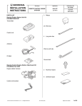
Accessory
INSTALLATION
INSTRUCTIONS
Application
REMOTE CONTROL
ENGINE STARTER
PARTS LIST
Publications No.
AII 43326-44956
2011 PILOT
Issue Date
SEPT 2010
Quick start guide
Remote Control Engine Starter Unit Kit
P/N 08E91-E22-101A
Transmitter
Remote Control Engine Starter Attachment Kit
P/N 08E92-SZA-100
Engine starter harness
Control unit
Control unit bracket
Antenna
Template
Key ring
Protective tape
2
Relays
Caution label
Flange nut
Fuse label
Ground bolt
Accessory User’s Information Manual
© 2010 American Honda Motor Co., Inc. – All Rights Reserved.
AII 43326-44956 (1009)
08E92-SZA-1000-91
1 of 21
16 Wire ties
Illustration of the Engine Starter Installed on the
Vehicle
ANTENNA
ENGINE STARTER
HARNESS
Long wire tie
5
Urethane tapes
792001AY
CONTROL
UNIT
TOOLS AND SUPPLIES REQUIRED
Flat-tip screwdriver
FUSE CASES
(3A, 3A, 40A)
INSTALLATION
Phillips screwdriver
Small flat-tip screwdriver
Ratchet
8 mm and10 mm Sockets
Combination wrench
Isopropyl alcohol
Shop towel
Tape measure
Customer Information: The information in this
installation instruction is intended for use only by skilled
technicians who have the proper tools, equipment, and
training to correctly and safely add equipment to your
vehicle. These procedures should not be attempted by
“do-it-yourselfers.”
NOTE:
This antenna should be installed only if the ambient
air temperature is 15°C (60°F) or above.
Scissors
Small rubber mallet
Honda Diagnostic System (HDS)
Masking tape
Needle nose pliers
1.
Make sure you have the anti-theft code for the audio
unit, then write down the radio station presets.
2.
Disconnect the negative cable from the battery.
Plastic trim tool
T/N SILTRIMTL 10
2 of 21
AII 43326-44956 (1009)
© 2010 American Honda Motor Co., Inc. – All Rights Reserved.
Setting the Control Unit
3.
6.
Touch the metal part of the screwdriver to any metal
part of the vehicle to discharge any static electricity.
Using isopropyl alcohol on a shop towel, clean the
area where the protective tape will attach. Remove
the adhesive backing from the protective tape,
attach the protective tape to the control unit over the
switches.
CONTROL
UNIT
CONTROL
UNIT
SMALL
FLAT-TIP
SCREWDRIVER
Discharge any
static electricity.
SWITCHES
SWITCHES
PROTECTIVE
TAPE
SET
SWITCHES
Clean with
isopropyl alcohol.
ADHESIVE
BACKING
772505AS
Removing the Vehicle Parts
7.
SW:1 RR Junction unit -----------------------> OFF
SW:2 Trunk or Tailgate ----------------------> OFF
Using a plastic trim tool, disengage the eight
retaining tabs and remove the left and right lenses
from the roof console.
SW:3 Smart Entry -----------------------------> OFF
ROOF
CONSOLE
SW:4 Horn or Buzzer Answerback ------> OFF
SW:5 Trunk Main SW -------------------------> OFF
SW:6 Reserve ----------------------------------> ON
7D2550AK
4.
RIGHT
LENS
Check the location of the switches on the control
unit.
NOTE:
5.
•
The switches must be set before the control unit
is plugged in.
•
If the switch setting is not correct, the remote
engine starter will not operate properly.
•
If you change the switch settings with the unit
connected, you must disconnect the unit, then
reconnect it before the new settings are
recognized.
LEFT
LENS
4 RETAINING
TABS
4 RETAINING
TABS
PLASTIC TRIM
TOOL
700602BB
Using a small flat-tip screwdriver, set the switches on
the control unit as shown.
© 2010 American Honda Motor Co., Inc. – All Rights Reserved.
AII 43326-44956 (1009)
3 of 21
8.
Open the sunglass holder.
11. Flip down the left sunvisor.
HOLDER
FLAT-TIP
SCREWDRIVER
VEHICLE
CONNECTOR
Push and hold the
retaining tab.
ROOF
CONSOLE
VANITY
MIRROR
LIGHT
CONNECTOR
SUNGLASS
HOLDER
(Open. )
2 SCREWS
(Black)
9.
Push upward.
700603BB
2 SCREWS
(Silver)
Remove the roof console (two black screws, two
silver screws, and unplug the vehicle connectors).
10. Rotate the two sunvisor holders 45°, and remove the
two sunvisor holders.
Rotate
towards
the door.
LEFT
SUNVISOR
(Turn rearward.)
840902AY
12. Locate the slot in the sunvisor holder, and insert a
flat-tip screwdriver into the slot. Push in and hold the
retaining tab.
13. While holding the retaining tab, push up on the left
sunvisor and rotate towards the door to remove the
sunvisor. Unplug the vanity mirror light connector.
SUNVISOR
HOLDER
If the retaining tab did not stay pushed in, return the
left sunvisor to its original position and repeat steps
11 through 13.
Turn.
2 SUNVISOR
HOLDERS
700215BE
4 of 21
AII 43326-44956 (1009)
© 2010 American Honda Motor Co., Inc. – All Rights Reserved.
14. Using a plastic trim tool, open the lid in the left
A-pillar trim (two retaining tabs).
LID
LEFT
A-PILLAR TRIM
2 RETAINING
TABS
18. Move the shift lever to D by pressing down on the
shift lock release with the ignition key. Remove the
left side center panel (eight clips and unplug the
vehicle connectors).
LEFT SIDE
CENTER
PANEL
LEFT
A-PILLAR TRIM
VEHICLE
CONNECTOR
8 CLIPS
BOLT
WEATHERSTRIP
(Pull away.)
CLIP
792203AE
15. Remove the bolt from the left A-pillar trim.
IGNITION KEY
16. Pull away the weatherstrip and remove the left
A-pillar trim (one clip).
17. Pull off the weatherstrip, then remove the left side
dashboard cover (seven retaining tabs).
WEATHERSTRIP
(Pull away.)
SHIFT
LEVER
VEHICLE
CONNECTOR
(If equipped)
792808AE
19. Remove the driver’s dashboard lower cover (12
clips, one self-tapping screw and unplug the vehicle
connectors). Remove the A/C sensor (two retaining
tabs).
A/C SENSOR
12 CLIPS
2 RETAINING
TABS
7 RETAINING
TABS
LEFT SIDE
DASHBOARD
COVER
792403CE
© 2010 American Honda Motor Co., Inc. – All Rights Reserved.
AII 43326-44956 (1009)
SELF-TAPPING
A/C SENSOR
SCREW
VEHICLE
792205CE
CONNECTOR DRIVER’S
DASHBOARD
LOWER COVER
5 of 21
20. Lower the tilt lever and pull the steering wheel out.
UPPER
STEERING
COLUMN
COVER
Routing the Engine Starter Harness
23. Attach the 40A fuse label to the engine starter
harness fuse block at the position shown.
2 SELF-TAPPING
SCREWS
4 RETAINING
TABS
FUSE LABEL
(3A)
FUSE LABEL
(40A)
FUSE BLOCK
Push.
TILT LEVER
ENGINE
STARTER
HARNESS
792404CE
21. Remove the upper steering column cover:
•
Remove the two self-tapping screws.
•
Push the upper cover inward at the areas shown
to release the four retaining tabs.
22. Remove the lower steering column cover (two selftapping screws and one screw).
840903AY
24. Attach the 3A fuse label to the engine starter harness
fuse block at the position shown.
25. Install the two relays to the engine starter harness
relay blocks.
LOWER
STEERING
COLUMN
COVER
RELAYS
ENGINE
STARTER
HARNESS
RELAY
BLOCK
SCREW
2 SELF-TAPPING
SCREWS
792003BY
792405AE
6 of 21
AII 43326-44956 (1009)
© 2010 American Honda Motor Co., Inc. – All Rights Reserved.
26. Plug the engine starter harness 28-pin connector
into the control unit.
28. Secure the control unit to the vehicle bracket with a
6 mm flange nut.
STEERING
WHEEL
28-PIN
CONNNECTOR
CONTROL
UNIT
STEERING
SHAFT
ENGINE
STARTER
HARNESS
792004AY
Hold against
the brackets.
27. Install the control unit bracket to the control unit.
CONTROL
UNIT
BRACKET
CONTROL
UNIT
VEHICLE
BRACKET
CONTROL
UNIT
BRACKET
VEHICLE
BRACKET
CONTROL
UNIT
CONTROL
UNIT
FLANGE NUT,
6 mm
STEERING
SHAFT
792401CY
792005AY
© 2010 American Honda Motor Co., Inc. – All Rights Reserved.
AII 43326-44956 (1009)
7 of 21
29. Install the engine starter harness fuse block clip on
the control unit bracket.
31. Route the engine starter harness relay block to the
right side of the vehicle.
ENGINE
STARTER
HARNESS
VEHICLE
RELAY BLOCK
CLIP
FUSE BLOCK
RELAY
BLOCK
CONTROL
UNIT
BRACKET
ENGINE
STARTER
HARNESS
792402AY
30. Install the engine starter harness clip on the vehicle
bracket.
792404AY
32. Install the engine starter harness relay block on the
vehicle relay block.
33. Remove the blue tape from the vehicle 4-pin
connector. Plug the engine starter harness 4-pin
connector to the vehicle 4-pin connector.
ENGINE
STARTER
HARNESS
STEERING
WHEEL
VEHICLE
4-PIN
CONNECTOR
(WHITE)
CLIP
VEHICLE
BRACKET
792403AY
BLUE TAPE
(Remove.)
ENGINE
STARTER
HARNESS
8 of 21
AII 43326-44956 (1009)
4-PIN CONNECTOR
792501AY
© 2010 American Honda Motor Co., Inc. – All Rights Reserved.
34. Secure the 4-pin connector to the vehicle harness
with one wire tie.
36. Locate and remove the blue tape from the vehicle 2pin connectors (white), and unplug the vehicle 2-pin
connectors as shown.
WIRE TIE
FUSE BOX
VEHICLE 2-PIN
CONNECTORS
(WHITE)
VEHICLE
HARNESS
BLUE
TAPE
4-PIN CONNECTORS
792502AY
35. Align the green-taped part of the engine starter
harness with the vehicle clip. Secure the engine
starter harness to the vehicle harness with one wire
tie.
WIRE TIE
VEHICLE
HARNESS
STEERING
SHAFT
7D0701BE
37. Plug the engine starter harness 2-pin connectors to
the vehicle 2-pin connectors as shown.
ENGINE
STARTER
HARNESS
FUSE
BOX
VEHICLE
2-PIN
CONNECTORS
2-PIN
CONNECTORS
FUSE
BOX
VEHICLE
CLIP
GREEN
TAPE
ENGINE STARTER
HARNESS
792503BY
STEERING
SHAFT
792706BY
38. Route the engine starter harness 2-pin connectors
behind the fuse box as shown.
© 2010 American Honda Motor Co., Inc. – All Rights Reserved.
AII 43326-44956 (1009)
9 of 21
39. Secure the 2-pin connectors to the vehicle harness
with one wire tie.
42. Route the engine starter harness ground terminal as
shown.
ENGINE STARTER
HARNESS GROUND
TERMINAL
PARKING
BRAKE
LEVER
ENGINE STARTER
HARNESS
FUSE
BOX
VEHICLE
HARNESS
WIRE TIE
2-PIN
CONNECTORS
STEERING
SHAFT
VEHICLE
BOLT
(Discard.)
792707EY
GROUND
BOLT
FUSE
BOX
792708BY
40. Cut the urethane tape into two equal parts, and cut a
10 mm piece from one half, as shown.
PARKING BRAKE
LEVER
43. Remove the vehicle bolt near the parking brake
lever, and discard it. Install the engine starter
harness ground terminal with the ground bolt from
the kit.
44. Loosely secure the engine starter harness to the
vehicle harness with two wire ties.
2 WIRE TIES
(Loosely secure.)
10 mm
URETHANE
TAPE
URETHANE
TAPE
VEHICLE
BRACKET
7D2401AB
41. Clean the vehicle bracket surface with isopropyl
alcohol where the urethane tape will attach. Attach
the 10 mm piece of urethane tape that you cut in step
40 to the vehicle bracket as shown.
10 of 21
AII 43326-44956 (1009)
ENGINE
STARTER
HARNESS
VEHICLE
HARNESS
792709BY
© 2010 American Honda Motor Co., Inc. – All Rights Reserved.
45. Route the engine starter harness 5-pin connector to
the ignition switch.
47. Unplug the vehicle 8-pin connector, and plug it into
the engine starter harness 8-pin connector. Plug the
remaining engine starter harness 8-pin connector
into the wiper switch.
IGNITION
SWITCH
8-PIN
CONNECTORS
5-PIN
CONNECTOR
VEHICLE
8-PIN
CONNECTOR
BODY
SWITCH
ENGINE
STARTER
HARNESS
WIPER
SWITCH
792702AY
ENGINE
STARTER
HARNESS
792601BY
48. Route the engine starter harness into the harness
case.
46. Unplug the vehicle 12-pin connector, and plug it into
the engine starter harness 12-pin connector. Plug
the remaining engine starter harness 12-pin
connector into the turn signal switch.
VEHICLE
12-PIN
CONNECTOR
12-PIN
CONNECTORS
HARNESS
CASE
ENGINE
STARTER
HARNESS
FRONT
TURN
SIGNAL
SWITCH
ENGINE
STARTER
HARNESS
792703AY
BODY
SWITCH
792701AY
© 2010 American Honda Motor Co., Inc. – All Rights Reserved.
AII 43326-44956 (1009)
11 of 21
49. Secure the 12-pin and 8-pin connectors to the
harness case with two wire ties.
50. Unplug the vehicle 5-pin connector from the ignition
switch, and plug the engine starter harness 5-pin
connector into the ignition switch.
12-PIN
CONNECTORS
HARNESS
CASE
Connector unlock
2
Pull.
Connector lock
Push. 2
1
Push.
1
3
5-PIN
CONNECTOR
2 WIRE TIES
FRONT
8-PIN
CONNECTORS
ENGINE
STARTER
HARNESS
VEHICLE
5-PIN
CONNECTOR
792704BY
5-PIN
CONNECTOR
ENGINE
STARTER
HARNESS
URETHANE
TAPE
5-PIN
CONNECTOR
792602CY
51. Plug the engine starter harness 5-pin connector into
the vehicle 5-pin connector.
NOTE: Make sure the engine starter harness 5-pin
connector is connected securely. A loose connection
can cause engine stalling.
52. Wrap one urethane tape around the 5-pin
connectors.
12 of 21
AII 43326-44956 (1009)
© 2010 American Honda Motor Co., Inc. – All Rights Reserved.
53. Take the 5-pin connectors you just connected, and
secure them in between the vehicle harness and the
engine starter harness with one long wire tie.
55. Secure the engine starter harness to the vehicle
harness with one wire tie as shown.
IGNITION SWITCH
ENGINE
STARTER
HARNESS
5-PIN
VEHICLE
CONNECTOR
HARNESS
LONG
WIRE TIE
CROSS
SECTION
VEHICLE
HARNESS
LONG
WIRE TIE
VEHICLE
HARNESS
5-PIN
CONNECTOR
792603DY
54. Unplug the vehicle 7-pin connector from the ignition
switch, and plug the engine starter harness 7-pin
connectors to the ignition switch and to the vehicle
7-pin connector.
VEHICLE
7-PIN
CONNECTOR
7-PIN
CONNECTOR
ENGINE
STARTER
HARNESS
WIRE
TIE
792705CY
56. Adjust the steering wheel in, out, up, and down while
you check the engine starter harness routing. If the
harness is rubbing against the steering column
bracket, check the installation and position of the
wire ties installed in steps 53 and 55.
IGNITION
SWITCH
ENGINE
STARTER
HARNESS
7-PIN
CONNECTOR
© 2010 American Honda Motor Co., Inc. – All Rights Reserved.
792604DY
AII 43326-44956 (1009)
13 of 21
Antenna Installation
59. Using scissors, cut out the template.
57. Bend the antenna plate according to the drawing
shown, using two needle nose pliers.
TEMPLATE
Cut out.
ANTENNA
Cut out.
13 mm
8 mm
PLATE
NEEDLE NOSE
PLIERS
7209041K
60. Align the template with edge of the black ceramic
paint as shown, then secure the template to the
windshield with masking tape.
BLACK
CERAMIC
PAINT
SCALE
792710AY
58. Starting near the antenna end of the cable, wrap
three urethane tapes around the antenna cable at
the measurements shown.
ANTENNA
FRONT
WINDOW
ANTENNA
CABLE
MIRROR
410 mm
TEMPLATE
MASKING
TAPES
6N3002AK
40 mm
URETHANE
TAPE
40
mm
701015AB
14 of 21
AII 43326-44956 (1009)
© 2010 American Honda Motor Co., Inc. – All Rights Reserved.
61. Using isopropyl alcohol on a shop towel, clean the
area where the antenna will attach. Allow to dry
before proceeding.
HEADLINER
65. Clean the vehicle panel surface with isopropyl
alcohol where the urethane tape will attach. Secure
the antenna cable to the vehicle panel with one half
of the urethane tape that you cut into two in step 40.
Be careful not to crease the headliner.
VEHICLE
PANEL
ANTENNA
CABLE
HEADLINER
URETHANE TAPE
1/2 of urethane
tape cut in step 40.
TEMPLATE
PLATE
ANTENNA
ADHESIVE
BACKING
6N3004BK
62. Remove the adhesive backing from the antenna,
insert the antenna plate under the headliner, and
attach the antenna to the windshield through the cutout in the template.
63. Remove the template.
64. Route the antenna cable to the left side of the
vehicle, and push it into the headliner as shown. Be
careful not to crease the headliner.
701016BB
66. Clean the vehicle panel surface where the urethane
tape will attach with isopropyl alcohol. Secure the
antenna cable to the vehicle panel with the
remaining part of the urethane tape you cut in step
40. Be careful not to crease the headliner.
Leftover urethane tape
from step 40.
HEADLINER
HEADLINER
VEHICLE
PANEL
URETHANE
TAPE
ANTENNA
CABLE
ANTENNA
CABLE
701017BB
6N30050K
© 2010 American Honda Motor Co., Inc. – All Rights Reserved.
AII 43326-44956 (1009)
15 of 21
67. Route the antenna cable along the left A-pillar and
secure the antenna cable to the vehicle harness with
four wire ties as shown.
69. Route the antenna cable along the engine starter
harness. Secure the antenna cable to the vehicle
harness with the two wire ties that were secured
loosely in step 44.
ANTENNA
CABLE
ANTENNA
CABLE
2 WIRE TIES
4 WIRE TIES
VEHICLE
HARNESS
LEFT
A-PILLAR
FUSE
BOX
VEHICLE
HARNESS
792711AY
68. Secure the antenna cable to the vehicle harness with
one wire tie.
VEHICLE
HARNESS
700102BY
70. Route the antenna cable terminal toward the right
side of the vehicle, and plug it into the control unit as
shown.
ANTENNA
CABLE
ANTENNA
CABLE
ANTENNA
CABLE
TERMINAL
WIRE TIE
DRIVER’S
DASHBOARD
COVER
OPENING
700101AY
CONTROL
UNIT
16 of 21
AII 43326-44956 (1009)
700103AY
© 2010 American Honda Motor Co., Inc. – All Rights Reserved.
71. Secure the engine starter harness and antenna
cable with one wire tie as shown.
2 WIRE TIES
77. Reconnect the negative cable to the battery.
Check that the electrical accessory and other
electrical systems function properly.
78. Enter the customer’s audio unit anti-theft code and
reset the radio station presets.
ANTENNA CABLE
(Bundle the excess.)
79. Reset the clock on models without navigation.
80. Do the “REMOTE ENGINE STARTER
REGISTRATION” and “FUNCTION CHECK.”
REMOTE ENGINE STARTER REGISTRATION
1.
Acquire the PCM code from the Interactive Network.
CAR ICON
WIRE TIE
ENGINE
STARTER
HARNESS
ANTENNA
CABLE
700104AY
72. Bundle the excess antenna cable. Secure the
antenna cable to the engine starter harness with two
wire ties.
73. Using isopropyl alcohol on a shop towel, clean the
hood where the caution label will attach.
HOOD
CAUTION
LABEL
2.
Connect the HDS tester to the OBD II data link
connector, then turn the ignition switch to ON (II).
3.
Turn on the HDS, and click the car icon.
4.
Input the VIN and other required information into the
HDS, then click the check button.
ADHESIVE
BACKING
7D0702AE
74. Attach the caution label to the hood in the area
shown.
75. Check that all wire harnesses and cables are routed
properly and that all connectors are plugged in.
76. Reinstall all removed parts. Check that all clips and
other fasteners are installed securely. Take care not
to pinch the side curtain airbag with the clip during
reinstallation of the left front A-pillar trim. Do not push
the front pillar trim excessively.
© 2010 American Honda Motor Co., Inc. – All Rights Reserved.
AII 43326-44956 (1009)
Input the VIN and other
required information.
CHECK BUTTON
752502AS
17 of 21
5.
Select Honda Systems, then click the check button.
7.
A REMARKS message will display. Click on the
check button.
“REMARKS” message
Select
“Honda Systems.”
CHECK BUTTON
752503AS
CHECK BUTTON
752505AS
6.
Select R/C ENG STARTER, and click the check
button.
Select
“R/C ENG STARTER.”
8.
Select REGISTER REMOTE CONTROL ENGINE
STARTER UNIT, then click the check button.
CHECK BUTTON
752504AS
Select
“REGISTER REMOTE CONTROL
ENGINE STARTER UNIT.”
CHECK BUTTON
752506AS
18 of 21
AII 43326-44956 (1009)
© 2010 American Honda Motor Co., Inc. – All Rights Reserved.
9.
The following message will display: Obtain PCMcode (IMMOBILIZER PCM CODE) from iN. This
vehicle’s VIN will be required to obtain the
password. (USA). Click on the check button.
11. The following message will display: The
registration of the Remote Control Engine Starter
Unit has been completed. Click on the check
button.
“Obtain PCM-code” message
“The registration of the Remote Control
Engine Starter Unit has been completed”.
CHECK BUTTON
CHECK BUTTON
752507AS
752510AS
10. Input the PCM code, then click the check button.
NOTE: To ensure security, the PCM code
(password) is changed everyday, so it is impossible
to register the remote control engine starter if the
dates of the PCM code acquisition and registration
are different. The date of the HDS tester should also
match.
12. The following message will display: Check that the
engine can be started by the Transmitter. Click on
the check button.
“Check that the engine can be started by
the Transmitter”.
Input the PCM Code.
CHECK BUTTON
752511AS
CHECK BUTTON
13. Perform the function test on the next page, then
disconnect the HDS.
752509AS
© 2010 American Honda Motor Co., Inc. – All Rights Reserved.
AII 43326-44956 (1009)
19 of 21
FUNCTION CHECK
Operating Conditions
• Hood is closed.
• Shift lever is in park.
• The key is not in the ignition switch.
• All doors and tailgate are closed and locked.
Inspection
1.
Press the command button on the transmitter and, within 1 second,
press the start button.
The engine should start if all operating conditions are met.
Does the engine start?
Yes - Operation is normal.
DISPLAY
No:
• Make sure all operating conditions are met.
• Check the engine starter harness connections.
• Connect the HDS and check for an indicated failure.
(Refer to the appropriate service manual for details.)
2.
STOP
BUTTON
COMMAND
BUTTON
Press the command button on the transmitter and, within 1 second,
press the stop button. The engine should stop.
START
BUTTON
Does the engine stop?
Yes - Operation is normal.
No - Check the engine starter harness connections.
TRANSMITTER
732904AY
3.
After the engine has stopped, start the engine again, and check that
the engine stops after each of the following conditions:
NOTE: After each test the ignition key must be cycled, or the driver’s door must be opened and closed
•
Move the shift lever out of the P position.
•
Unlock or open the doors or the tailgate.
•
Open the hood.
•
Insert the key in the ignition switch.
•
Press on the brake pedal.
Does the engine stop after each of these tests?
Yes - Operation is normal.
No - Check the engine starter harness connections.
4.
Check that the power windows or the moon roof does not function when the engine is started with the transmitter.
5.
Press the command button on the transmitter two times and check the vehicle condition on the display.
6.
Check the operation of the transmitter when the vehicle is 100 m to 150 m (325 to 490 ft.) away, and in direct sight.
20 of 21
AII 43326-44956 (1009)
© 2010 American Honda Motor Co., Inc. – All Rights Reserved.
How to Program an Additional Transmitter
1.
Connect the HDS to the data link connector.
2.
Start the HDS and click on the car icon.
3.
Input the vehicle’s VIN and other required
information.
4.
Select Honda Systems.
5.
Select R/C Engine Starter.
6.
Select REGISTER NEW TRANSMITTER.
7.
When “Ready to program the new transmitter”
shows, select ENTER.
8.
Press and release the Command button.
9.
Press and release the Stop button.
10. Perform the function check on both transmitters.
NOTE: Only 2 remotes can be stored in the system’s
memory.
© 2010 American Honda Motor Co., Inc. – All Rights Reserved.
AII 43326-44956 (1009)
21 of 21