1
INSTALLATION
INSTRUCTIONS
Accessory
Application
REMOTE CONTROL ENGINE
STARTER
2015 FIT
Publications No.
AII 51168
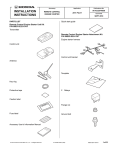
PARTS LIST
3
(LX ONLY)
Issue Date
APR 2014
Relays
Remote Engine Starter Unit Kit
P/N 08E91-E54-100
Transmitter
20 Wire ties
Control unit
4
Long wire ties
Antenna
Wire tie with clip
ID label
Ground bolt
Remote Control Engine Starter Attachment Kit
P/N 08E92-T5A-100A
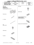
Engine starter harness
2
Aluminum tapes
8
Urethane tapes
Control unit bracket
© 2014 American Honda Motor Co., Inc. – All Rights Reserved.
AII 51168 (1404)
08E92-T5A-1A00-90
1 of 29
Caution label
TOOLS AND SUPPLIES REQUIRED
Phillips screwdriver
Flat-tip screwdriver
Diagonal cutters
Ratchet
Fuse label
10 mm Socket
10 mm Open end wrench
Isopropyl alcohol
Scissors
Shop towel
Clip
Ruler
Tape measure
HDS/MVCI
Masking tape
Tape
Accessory User’s Information Manual
The following tools are available through the Honda Tool
and Equipment Program. On the iN, click on: Service >
Service Bay > Tool and Equipment Program, then enter
the number under “Search”. Or, call 888-424-6857.
• Trim Tool Set (T/N SOJATP2014)
• Plastic Trim Tool (T/N SILTRIMTL10)
Quick Start Guide
Illustration of the Remote Control Engine Starter
Installed on the Vehicle
ANTENNA
40A FUSES
CONTROL
UNIT
3 RELAYS
3A FUSE
QC72001AJ
ENGINE STARTER
HARNESS
2 of 29
AII 51168 (1404)
© 2014 American Honda Motor Co., Inc. – All Rights Reserved.
INSTALLATION
3.
Customer Information: The information in this
installation instruction is intended for use only by skilled
technicians who have the proper tools, equipment, and
training to correctly and safely add equipment to your
vehicle. These procedures should not be attempted by
“do-it-yourselfers.”
•
Pivot the driver’s sunvisor downward.
•
Wrap tape around the tip of flat-tip screwdriver.
•
Locate the slot in the base cover, and insert the
flat-tip screwdriver into the slot. Push in and hold
the retaining tab.
•
While holding the retaining tab, push up on the
sunvisor and rotate it.
NOTE: If the retaining tab did not stay pushed in, return
the sunvisor to its original position and repeat this step.
NOTE: This antenna should only be installed if the
ambient air temperature 15°C (60°F) or above.
1.
Remove the driver’s sunvisor:
Disconnect the negative cable from the battery.
FLAT-TIP
SCREWDRIVER
2.
BASE
COVER
RETAINING
TAB
Attach the ID label.
•
Using isopropyl alcohol on a shop towel, clean
the transmitter where the ID label will attach.
•
Attach the ID label to the transmitter in the area
as shown.
TAPE
ID LABEL
FRONT
TRANSMITTER
DRIVER’S
SUNVISOR
Make sure the
tab slides into
the base cover.
Clean with
isopropyl
alcohol.
QBD0601AE
Push the
retaining tab.
© 2014 American Honda Motor Co., Inc. – All Rights Reserved.
AII 51168 (1404)
While pushing in
on the tab, rotate
the sunvisor.
QC71812AJ
3 of 29
4.
Remove the left sunvisor holder:
5.
Remove the driver’s A-pillar trim.
•
Wrap tape around the tip of flat-tip screwdriver.
•
•
Release three retaining tabs on the left sunvisor
holder.
Pull back the door opening seal from the driver’s
A-pillar trim.
•
Pull out on the driver’s A-pillar trim to release
three clips.
FLAT-TIP
SCREWDRIVER
3 RETAINING
TABS
(Push.)
Pull
the clip.
DRIVER’S A-PILLAR
SECTION VIEW
TAPE
2 CLIPS
DRIVER’S
A-PILLAR
TRIM
LEFT SUNVISOR
HOLDER
QC22003BJ
•
While holding down the left sunvisor holder, use
a flat-tip screwdriver wrapped with a tape to
remove the left sunvisor holder.
3 RETAINING
TABS
(Push.)
DOOR
OPENING
SEAL
(Pull back.)
DRIVER’S
A-PILLAR
TRIM
QC71813AJ
Hold down.
FLAT-TIP
SCREWDRIVER
LEFT SUNVISOR
HOLDER
4 of 29
QC22004AJ
AII 51168 (1404)
© 2014 American Honda Motor Co., Inc. – All Rights Reserved.
•
To prevent clips from falling into the body panel
area, carefully insert a shop towel between the
driver’s A-pillar and the driver’s A-pillar trim.
6.
DRIVER’S
A-PILLAR TRIM
Remove the remaining upper clip from the driver’s Apillar.
Push
two tabs.
DRIVER’S
A-PILLAR
UPPER CLIP
(Discard.)
SHOP TOWEL
QC71814AJ
•
Slide the driver’s A-pillar trim upward, and
remove the driver’s A-pillar trim.
•
Remove the shop towel and any clips.
DRIVER’S A-PILLAR
TRIM
7.
DRIVER’S
A-PILLAR
QC71816AJ
Install the new clip (supplied) to the driver’s A-pillar
trim.
CLIP
(supplied)
UPPER
CLIP
DRIVER’S
A-PILLAR TRIM
QC71817AJ
DRIVER’S A-PILLAR
TRIM
© 2014 American Honda Motor Co., Inc. – All Rights Reserved.
QC71815AJ
AII 51168 (1404)
5 of 29
8.
Pull back the door opening seal, and remove the
driver’s dashboard side lid.
10. Pull back the door opening seal, and remove the
driver’s front door sill trim.
3 RETAINING
TABS
DOOR OPENING SEAL
(Pull back.)
DRIVER’S
DASHBOAR
D SIDE LID
9.
5 RETAINING
TABS
DOOR OPENING
SEAL
(Pull back.)
QC71818AJ
3 RETAINING
TABS
DRIVER’S FRONT
DOOR SILL TRIM
QC71820BJ
11. Pull back the door opening seal, and remove the
driver’s kick panel.
Remove the driver’s dashboard lower cover, and
unplug the vehicle connectors.
CLIP
2 CLIPS
VEHICLE
CONNECTORS
DOOR
OPENING
SEAL
(Pull back.)
4 RETAINING
TABS
4 CLIPS
BOLT
DRIVER’S
KICK PANEL
DRIVER’S
DASHBOARD
LOWER COVER
6 of 29
2 CLIPS
QC71821AJ
QC71819AJ
AII 51168 (1404)
© 2014 American Honda Motor Co., Inc. – All Rights Reserved.
12. Lower the steering wheel. Attach the tape to the
upper column cover as shown.
UPPER
COLUMN
COVER
14. Turn the steering wheel 180° counterclockwise.
Using a plastic trim tool, release the retaining tab.
TAPE
UPPER
COLUMN
COVER
RETAINING TAB
PLASTIC TRIM
TOOL
QC71824AJ
15. Remove the upper column cover
STEERING
WHEEL
QC71822AJ
2 HOOKS
UPPER COLUMN
COVER
4 RETAINING TABS
13. Turn the steering wheel 90° clockwise. Using a
plastic trim tool, release the retaining tab.
UPPER
COLUMN
COVER
QC71825AJ
RETAINING
TAB
PLASTIC TRIM TOOL
© 2014 American Honda Motor Co., Inc. – All Rights Reserved.
QC71823AJ
AII 51168 (1404)
7 of 29
16. Remove the self-tapping screw from the lower
column cover.
LOWER
COLUMN
COVER
SELF-TAPPING
SCREW
18. Remove the lower column cover.
SELF-TAPPING
SCREW
LOWER COLUMN
COVER
QC71903AJ
QC71901AJ
Installing the Antenna
17. Turn the steering wheel 180° clockwise, and remove
the self-tapping screw from the lower column cover.
19. Using scissors, cut one urethane tape in half. Wrap
the two halves of urethane tape around the antenna
cable as shown.
NOTE: Do not fold the antenna cable.
ANTENNA
60 mm
(2.4 in.)
60 mm
(2.4 in.)
ANTENNA
CABLE
SECTION
VIEW
LOWER
COLUMN
COVER
SELF-TAPPING
SCREW
QC71902AJ
URETHANE TAPE
(Cut in half.)
8 of 29
AII 51168 (1404)
2 HALVES OF
URETHANE
TAPE
QB62501BK
© 2014 American Honda Motor Co., Inc. – All Rights Reserved.
20. Using scissors, cut three urethane tapes in half.
Starting near the antenna end of the cable, wrap five
halves of urethane tape around the antenna cable as
shown.
21. Attach the antenna.
•
Attach masking tape to the windshield at the
measurement shown.
ANTENNA
MASKING
TAPE
220 mm
(8.7 in.)
WINDSHIELD
MASKING
TAPE
50 mm
(2.0 in.)
25 mm
(1.0 in.)
270 mm
(10.6 in.)
660 mm
(26.0 in.)
ANTENNA
CABLE
SECTION
VIEW
WINDSHIELD
ANTENNA
CABLE
3 URETHANE TAPES
(Cut in half.)
5 HALVES OF
URETHANE
TAPE
•
QC71301AJ
Fold the adhesive backing of the antenna as
shown.
QC71912BJ
ADHESIVE
BACKING
ANTENNA
QB51401CH
© 2014 American Honda Motor Co., Inc. – All Rights Reserved.
AII 51168 (1404)
9 of 29
•
Using isopropyl alcohol on a shop towel, clean
the windshield where the antenna will attach.
•
Attach the antenna with masking tape. Adjust
the position of the antenna so there is equal
spacing on both sides.
Clean with
isopropyl alcohol.
•
Carefully remove the adhesive backing from the
antenna, and attach the antenna to the
windshield. Press and hold the antenna firmly in
place for 30 seconds.
•
Remove the masking tape.
ANTENNA
WINDSHIELD
MASKING TAPE
(Remove.)
ADHESIVE
BACKING
(Remove.)
HEADLINER
ANTENNA
Equal spacing on both sides.
QC71303AJ
MASKING
TAPE
22. Gently pull down the headliner, and tuck the antenna
cable under the headliner. Be careful not to crease
the headliner.
ANTENNA
WINDSHIELD
QC71302AJ
VEHICLE
PANEL
ANTENNA
CABLE
HEADLINER
HEADLINER
SECTION VIEW
ANTENNA CABLE
10 of 29
AII 51168 (1404)
QC71304BJ
© 2014 American Honda Motor Co., Inc. – All Rights Reserved.
23. Route the antenna cable down the A-pillar as shown.
Secure the antenna cable to the vehicle harness with
four wire ties.
Routing the Engine Starter Harness
24. Using isopropyl alcohol on a shop towel, clean the
engine starter harness fuse block where the fuse
label will attach.
ANTENNA CABLE
VEHICLE
PANEL
Clean with ENGINE STARTER
isopropyl HARNESS
alcohol.
FUSE BLOCK
WIRE TIE
VEHICLE
HARNESS
SECTION VIEW
VEHICLE
HARNESS
Clean with
isopropyl alcohol.
ANTENNA
CABLE
2 FUSE
LABELS
(40A ENG.
STARTER)
FUSE
LABEL
(3A ENG.
STARTER)
ENGINE
STARTER
HARNESS
FUSE
BLOCK
4 WIRE
TIES
QC72002AJ
Do not cover the
installation holes.
QD22201AJ
25. Attach three fuse labels to the engine starter harness
fuse block.
26. Install three relays to the engine starter harness
relay block.
3 RELAYS
ENGINE STARTER
HARNESS
RELAY BLOCK
QC71307AJ
© 2014 American Honda Motor Co., Inc. – All Rights Reserved.
AII 51168 (1404)
11 of 29
• If the vehicle is equipped with a moonroof, continue
with step 27; otherwise, go to step 28.
29. Attach the engine starter harness clip onto the
vehicle 18-pin connector.
With Moonroof
DRIVER’S A-PILLAR
27. Unplug the vehicle 18-pin connector, and plug it into
the engine starter harness 18-pin connector. Plug
the remaining engine starter harness 18-pin
connector into the vehicle 18-pin connector.
Go to step 29.
DRIVER’S
A-PILLAR
VEHICLE
18-PIN
CONNECTORS
ENGINE STARTER
HARNESS CLIP
VEHICLE 18-PIN
CONNECTOR
QC71509AJ
30. Secure the antenna cable, engine starter harness,
and engine starter harness 18-pin connector to the
vehicle harness with one wire tie.
ENGINE STARTER HARNESS
18-PIN CONNECTORS
QC71308AJ
VEHICLE
HARNESS
ENGINE STARTER
HARNESS
18-PIN CONNECTOR
ANTENNA
CABLE
Without Moonroof
28. Plug the engine starter harness 18-pin connector
into the engine starter harness 18-pin connector.
WIRE
TIE
SECTION
VIEW
VEHICLE
PANEL
WIRE
TIE
ENGINE
STARTER
HARNESS
18-PIN
CONNECTOR
ENGINE STARTER HARNESS
18-PIN CONNECTORS
ENGINE
STARTER
HARNESS
ANTENNA
CABLE
VEHICLE
ENGINE
HARNESS
STARTER
HARNESS
QC71510AJ
QC71309AJ
12 of 29
AII 51168 (1404)
© 2014 American Honda Motor Co., Inc. – All Rights Reserved.
31. Pull back the door opening seal. Route the antenna
cable and engine starter harness along the
instrument panel, and tuck the antenna cable and
engine starter harness between the driver’s A-pillar
and the instrument panel.
DRIVER’S
A-PILLAR
34. Secure the antenna cable and engine starter
harness to the steering hanger beam with one wire
tie.
INSTRUMENT PANEL
WIRE
TIE
ANTENNA
CABLE
ENGINE STARTER
HARNESS
STEERING
HANGER BEAM
DOOR OPENING
SEAL
(Pull back.)
ENGINE STARTER
HARNESS
ANTENNA
CABLE
QC72005BJ
35. Secure the antenna cable and engine starter
harness to the vehicle harness with one long wire tie.
QC72003AJ
VEHICLE
HARNESS
32. Using isopropyl alcohol on a shop towel, clean the
driver’s A-pillar where the aluminum tapes will
attach.
Clean with
isopropyl alcohol.
DRIVER’S
A-PILLAR
LONG
WIRE TIE
ANTENNA
CABLE
ANTENNA
CABLE
ENGINE
STARTER
HARNESS
2 ALUMINUM
TAPES
ENGINE STARTER
HARNESS
QC72006AJ
QC72004AJ
33. Attach the antenna cable and engine starter harness
to the driver’s A-pillar with aluminum tape.
© 2014 American Honda Motor Co., Inc. – All Rights Reserved.
AII 51168 (1404)
13 of 29
36. Route the engine starter harness along the vehicle
harness. Remove the bolt, and install the engine
starter harness ground terminal with one ground
bolt.
38. Release the subfuse box from the subfuse box
bracket.
SUBFUSE BOX
BRACKET
VEHICLE
HARNESS
GROUND
BOLT
HOOD
OPENER
BOLT
(Discard.)
2 RETAINING
TABS
ENGINE STARTER
HARNESS GROUND
TERMINAL
QC71609AJ
SUBFUSE
BOX
QC71701BJ
39. Remove the subfuse box bracket.
37. Secure the engine starter harness to the vehicle
harness with two wire ties.
SUBFUSE BOX BRACKET
ENGINE STARTER
HARNESS
2 WIRE
TIES
2 NUTS
VEHICLE HARNESS
14 of 29
QC71702BJ
QC71610AJ
AII 51168 (1404)
© 2014 American Honda Motor Co., Inc. – All Rights Reserved.
40. Plug the antenna cable connector and engine starter
harness 28-pin connector into the control unit.
44. Attach the engine starter harness clip to the control
unit bracket.
CONTROL UNIT
BRACKET
ENGINE STARTER
HARNESS 28-PIN
CONNECTOR
CONTROL
UNIT
ENGINE STARTER
HARNESS CLIP
ANTENNA CABLE
CONNECTOR
QD22202AJ
QD22204AJ
41. Using isopropyl alcohol on a shop towel, clean the
control unit bracket where the urethane tape will
attach.
45. Secure the subfuse box bracket (removed in step
39) and control unit bracket to the studs with two nuts
in the order shown.
CONTROL UNIT
BRACKET
SUBFUSE BOX
BRACKET
2 NUTS
(reused.)
CONTROL UNIT
2
1
Cut in half.
2 STUDS
Align.
Clean with
URETHANE
isopropyl alcohol.
TAPE
(From step 20.)
QD22203BJ
SUBFUSE BOX
BRACKET
CONTROL UNIT
BRACKET
CONTROL UNIT
BRACKET
QC71713AJ
46. Reinstall the subfuse box released in step 38.
42. Using scissors, cut the remaining urethane tape in
step 20 in half. Wrap the cut urethane tape around
the control unit bracket as shown.
43. Install the control unit bracket to the control unit.
© 2014 American Honda Motor Co., Inc. – All Rights Reserved.
AII 51168 (1404)
15 of 29
47. Secure the engine starter harness fuse block to the
hole in the subfuse box bracket. If another accessory
relay block is already secured to the holes in the
subfuse box bracket, secure the engine starter
harness fuse block to another accessory relay block.
Without Another Accessory Harness 4-pin
Connector
48. Plug the engine starter harness 4-pin connector into
the fuse box. Go to step 50.
ENGINE STARTER
HARNESS
FUSE BLOCK
ENGINE
STARTER
HARNESS
4-PIN
CONNECTOR
Plug in here.
SUBFUSE BOX
BRACKET
WITH ANOTHER ACCESSORY RELAY BLOCK
FUSE
BOX
FRONT VIEW
QC72017BJ
CLIP
(Discard.)
16 of 29
ENGINE
STARTER
HARNESS
FUSE
BLOCK
QC71714BJ
ANOTHER
ACCESSORY
ENGINE
RELAY
STARTER
BLOCK
HARNESS
FUSE
BLOCK
AII 51168 (1404)
© 2014 American Honda Motor Co., Inc. – All Rights Reserved.
With Another Accessory Harness 4-pin Connector
49. If another accessory harness 4-pin connector is
plugged into the fuse box, unplug the 4-pin
connector from the fuse box, then plug the engine
starter harness 4-pin connector into the fuse box.
Plug another accessory harness 4-pin connector into
the engine starter harness 4-pin connector.
50. Unplug the vehicle 25-pin connector, and plug it into
the engine starter harness 25-pin connector. Plug
the remaining engine starter harness 25-pin
connector into the vehicle 25-pin connector.
VEHICLE 25-PIN
CONNECTORS
ANOTHER
ACCESSORY
HARNESS 4-PIN
CONNECTORS
FUSE
BOX
Plug in
here.
Plug in
here.
FRONT VIEW
SUBFUSE
BOX
FRONT VIEW
ENGINE STARTER
HARNESS 4-PIN
CONNECTORS
QC72018BJ
SUBFUSE
BOX
ENGINE STARTER
QC71611DJ
HARNESS 25-PIN
CONNECTORS
51. Secure the engine starter harness 25-pin connector
and engine starter harness to the vehicle harness
with one wire tie and one long wire tie.
ENGINE STARTER HARNESS
25-PIN CONNECTORS
WIRE
TIE
LONG
WIRE TIE
VEHICLE
HARNESS
ENGINE
STARTER
HARNESS
Do not cover the
installation holes.
© 2014 American Honda Motor Co., Inc. – All Rights Reserved.
AII 51168 (1404)
QC71612BJ
17 of 29
52. Route the engine starter harness behind steering
shaft as shown. Secure the engine starter harness
relay block to the hole in the vehicle panel.
54. Secure the engine starter harness to the steering
hanger beam with one wire tie.
WIRE TIE
BRAKE PEDAL
BRACKET
VEHICLE
ENGINE STARTER
PANEL
STEERING HARNESS
RELAY BLOCK
SHAFT
QC71715AJ
53. Align the white tape on the engine starter harness
with the vehicle clip, and secure the engine starter
harness to the vehicle harness with four wire ties.
ENGINE STARTER
HARNESS
QCN0501AJ
55. Route the engine starter harness along the vehicle
harness. Align the white tape on the engine starter
harness with end of the vehicle harness protector,
and secure the engine starter harness to the vehicle
harness with one wire tie.
VEHICLE
CLIP
VEHICLE
WHITE TAPE
ENGINE
STARTER
HARNESS
STEERING
HANGER
BEAM
HARNESS
VEHICLE
HARNESS
END OF
THE VEHICLE
HARNESS
PROTECTOR
2 WIRE TIES
WIRE TIE
2 WIRE TIES
18 of 29
VEHICLE
HARNESS
WHITE TAPE
QC71716BJ
AII 51168 (1404)
ENGINE STARTER
HARNESS
QC72007BJ
© 2014 American Honda Motor Co., Inc. – All Rights Reserved.
56. Unplug the vehicle 10-pin connector from the wiper
switch, and plug it into the engine starter harness 10pin connector. Plug the remaining engine starter
harness 10-pin connector into the wiper switch.
57. Align the white tape on the engine starter harness
with the vehicle clip, and secure the engine starter
harness and engine starter harness 10-pin
connector to the vehicle harness with one wire tie.
Do not undue strain to
the 10-pin connector cord.
WHITE
TAPE
ENGINE
STARTER
HARNESS
VEHICLE
HARNESS
VEHICLE 10-PIN
CONNECTOR
ENGINE STARTER
HARNESS 10-PIN
CONNECTOR
ENGINE
STARTER
HARNESS
10-PIN
CONNECTORS
WIRE TIE
VEHICLE
CLIP
ENGINE
STARTER
HARNESS
WIPER
SWITCH
QC72009BJ
QC72008BJ
© 2014 American Honda Motor Co., Inc. – All Rights Reserved.
AII 51168 (1404)
19 of 29
58. Unplug the vehicle 12-pin connector from the
combination light switch, and plug it into the engine
starter harness 12-pin connector. Plug the remaining
engine starter harness 12-pin connector into the
combination light switch.
59. Align the white tape on the engine starter harness
with the vehicle clip, and secure the engine starter
harness and engine starter harness 12-pin
connector to the vehicle harness with one wire tie.
Do not undue strain to
the 12-pin connector cord.
VEHICLE
HARNESS
WHITE
TAPE
VEHICLE
CLIP
WIRE
TIE
VEHICLE 12-PIN
CONNECTOR
ENGINE
STARTER
HARNESS
12-PIN
CONNECTOR
ENGINE
STARTER
HARNESS
12-PIN
CONNECTORS
20 of 29
ENGINE STARTER
HARNESS
COMBINATION
LIGHT SWITCH
QC72011AJ
QC72010AJ
AII 51168 (1404)
© 2014 American Honda Motor Co., Inc. – All Rights Reserved.
60. Unplug the vehicle 7-pin connector, and plug it into
the engine starter harness 7-pin connector. Plug the
remaining engine starter harness 7-pin connector
into the vehicle 7-pin connector.
62. Using scissors, cut one urethane tape as shown.
Wrap the cut urethane tape around the engine
starter harness 5-pin connector.
VIEW FROM
URETHANE SIDE
20 mm (0.8 in.)
25 mm
(1.0 in.)
ENGINE STARTER
HARNESS 5-PIN
CONNECTOR
URETHANE
TAPE
VEHICLE 7-PIN
CONNECTOR
ENGINE
STARTER
HARNESS
7-PIN
CONNECTORS
VEHICLE 7-PIN
CONNECTOR
ENGINE STARTER
HARNESS
QC72014AJ
QC72012AJ
61. Secure the engine starter harness 7-pin connector to
the vehicle harness with one wire tie.
VEHICLE HARNESS
ENGINE STARTER
HARNESS 7-PIN
CONNECTOR
© 2014 American Honda Motor Co., Inc. – All Rights Reserved.
WIRE
TIE
QC72013AJ
AII 51168 (1404)
21 of 29
63. Unplug the vehicle 5-pin connector, and plug it into
the engine starter harness 5-pin connector. Plug the
remaining engine starter harness 5-pin connector
into the vehicle 5-pin connector.
NOTICE: Make sure the engine starter harness 5-pin
connector is securely connected to the vehicle 5-pin
connector. A loose connection can cause the engine to
stall during driving.
64. Align the white tape on the engine starter harness
with the vehicle clip, and secure the engine starter
harness and engine starter harness 5-pin connector
to the vehicle harness with one wire tie and one long
wire tie.
NOTE: Make sure that the connectors and harness
are not pinched, or interfering the steering wheel
when moved for adjustment.
ENGINE STARTER
HARNESS
Connector unlock
2 Pull.
1 Push.
Connector lock
WIRE
TIE
2 Push.
ENGINE
STARTER
HARNESS
5-PIN
CONNECTOR
LONG
WIRE TIE
1
Plug.
3 Unplug.
VEHICLE
CLIP
WHITE
TAPE
VEHICLE HARNESS
SECTION VIEW
VEHICLE 5-PIN
CONNECTOR
VEHICLE HARNESS
VEHICLE
ENGINE STARTER
5-PIN
CONNECTOR HARNESS 5-PIN
CONNECTORS
22 of 29
VEHICLE
BRACKET
QC72015AJ
Be careful not to install the
engine starter harness
above the vehicle harness.
LONG
WIRE ENGINE STARTER
HARNESS 5-PIN
TIE
CONNECTOR
QC72016EJ
ENGINE STARTER
HARNESS
AII 51168 (1404)
© 2014 American Honda Motor Co., Inc. – All Rights Reserved.
65. Secure the engine starter harness and antenna
cable to the knee bolster with one long wire tie.
LONG WIRE TIE
KNEE
BOLSTER
ANTENNA
CABLE
66. Secure one wire tie with clip to the antenna cable
and engine starter harness at the white tape, and
secure the wire tie with clip to the hole in the steering
hanger beam.
NOTE: If another accessory harness is already
attached, using diagonal cutters, cut the clip portion
off of one wire ties with a clip. Align the white tape on
the engine starter harness with the clip on the other
harness, and secure the engine starter harness and
antenna cable to the other accessory harness with
one wire tie with clip.
STEERING
HANGER
BEAM
ENGINE STARTER
HARNESS
QCN0502AJ
WHITE
TAPE
WIRE TIE
WITH CLIP
ENGINE STARTER
HARNESS
ANTENNA WITH OTHER
CABLE
ACCESSORY HARNESS
WIRE TIE
WITH CLIP
WHITE
TAPE
WIRE TIE
WITH CLIP
Cut off.
ANTENNA
CABLE
OTHER
ACCESSORY
HARNESS CLIP
© 2014 American Honda Motor Co., Inc. – All Rights Reserved.
AII 51168 (1404)
QC71806CJ
ENGINE STARTER
HARNESS
23 of 29
67. Bundle up the excess antenna cable as shown, and
wrap one urethane tape around the antenna cable.
Secure the antenna cable to the engine starter
harness with one wire tie.
NOTE: Do not fold the antenna cable.
68. Using isopropyl alcohol on a shop towel, clean the
lower column cover where the urethane tape will
attach.
URETHANE
TAPE
Clean with
isopropyl alcohol.
WIRE
TIE
ENGINE
STARTER
HARNESS
LOWER
COLUMN
COVER
30 mm (1.2 in.)
or above.
QC71808AJ
69. Attach the urethane tape to the lower column cover
as shown.
180 mm
(7.1 in.)
70. Using isopropyl alcohol on a shop towel, clean the
lower column cover where the urethane tape will
attach.
URETHANE
TAPE
ANTENNA CABLE
(Bundle up the excess.)
QCN0503AJ
URETHANE TAPE
(Cut in half.)
Clean with
isopropyl
alcohol.
2 HALVES OF
URETHANE TAPE
LOWER
COLUMN
COVER
QC71809AJ
71. Using scissors, cut one urethane tape in half. Attach
two halves of urethane tape to the lower column
cover as shown.
24 of 29
AII 51168 (1404)
© 2014 American Honda Motor Co., Inc. – All Rights Reserved.
72. Using isopropyl alcohol on a shop towel, clean the
hood where the caution label will attach.
Clean with
isopropyl alcohol.
REMOTE ENGINE STARTER REGISTRATION
NOTE: Register after making sure the HDS has been
upgraded to the latest version as described in the Service
News.
1.
Acquire the PCM Code from the Interactive Network.
HOOD
CAR ICON
CAUTIO
N LABEL
ADHESIVE
BACKING
(Remove.)
QC71810AJ
73. Remove the adhesive backing from the caution
label, and attach the caution label to the hood as
shown.
QC31909AC
74. Check that all wire harnesses are routed properly
and all connectors are plugged in.
2.
Connect the HDS/MVCI tester to the OBD II data link
connector, then turn the engine switch to ON.
75. Check the overlap between the headliner and the
driver’s A-pillar trim. Refer to the Service Manual. If
necessary, adjust the overlap.
3.
Start the HDS, and click the car icon.
4.
Input the VIN and other required information into the
HDS, then click the check button.
76. Reinstall all removed parts.
77. Reconnect the negative cable to the battery.
78. Press and hold the radio power button for two
seconds to restore the radio and navi (if equipped)
system functions.
79. Reset the clock.
80. Restore the systems back to normal operation as
described in the Service Manual if necessary.
81. Perform the “REMOTE ENGINE STARTER
REGISTRATION” and the “FUNCTION CHECK.”
Input the VIN and other
required information.
CHECK BUTTON
QB32102BH
© 2014 American Honda Motor Co., Inc. – All Rights Reserved.
AII 51168 (1404)
25 of 29
5.
Select Honda Systems, then click the check button.
7.
Select
“Honda Systems.”
Select REGISTER REMOTE CONTROL ENGINE
STARTER UNIT, then click the check button.
Select
“REGISTER REMOTE
CONTROL ENGINE
STARTER UNIT.”
CHECK BUTTON
CHECK BUTTON
QB32103AH
QB32105BH
6.
Select R/C ENG STARTER and click the check
button.
8.
Select
“R/C ENG STARTER.”
The following message will display: Obtain PCMcode (IMMOBILIZER PCM CODE) from iN. This
vehicle’s VIN will be required to obtain the
password. (USA) Click the check button.
“Obtain PCM-code”
message.
CHECK BUTTON
QB32104AH
CHECK BUTTON
QB32106AH
26 of 29
AII 51168 (1404)
© 2014 American Honda Motor Co., Inc. – All Rights Reserved.
9.
Input the PCM-code, then click the check button.
NOTE: To ensure security, the PCM-code
(password) is changed everyday, so it is impossible
to register the remote control engine starter if the
dates of the PCM-code acquisition and registration
are different. The date of the HDS/MVCI tester
should also be the same.
11. The following message will display: Check that
engine can be started by the Transmitter. Click
the check button.
“Check that engine can be
started by the Transmitter.”
Input the PCM-Code.
CHECK BUTTON
CHECK BUTTON
QB32109CH
12. Perform the FUNCTION CHECK on page 28, then
disconnect the HDS/MVCI.
QB32107BH
10. The following message will display: The
registration of the Remote Control Engine Starter
Unit has been completed. Turn the engine switch
to OFF.
“The registration of the
Remote Control Engine
Starter Unit has been
completed.”
QB32108CH
© 2014 American Honda Motor Co., Inc. – All Rights Reserved.
AII 51168 (1404)
27 of 29
FUNCTION CHECK
Operating Conditions
• The hood is closed
• The shift lever is in park
• Turn the engine switch to OFF and the key is outside the vehicle
• All doors and tailgate closed and locked
Inspection
1.
Press the engine/command button on the transmitter and release, within 2 seconds, press the lock/start button on
the transmitter.
The engine should start if all operating conditions are met.
Does the engine start?
Yes - Operation is normal.
No:
• Make sure all “Operating Conditions” are met.
• Check the engine starter harness connections.
• Connect the HDS/MVCI and check for an indicated
failure. (Refer to the appropriate Service Manual for
details.)
2.
ENGINE START
OPERATION
Press the engine/command button on the transmitter
and release, within 2 seconds, press the unlock/stop
button. The engine should stop.
CHECKING
INDICATOR
Does the engine stop?
Yes - Operation is normal.
After the engine has stopped, start the engine again,
and check that the engine stops after each of the
following conditions:
NOTE: After each test the ignition key must be cycled, or the
driver’s door must be opened and closed.
•
Move the shift lever out of the P position.
•
Unlock or open the doors or the tailgate.
•
Open the hood.
•
Insert the key in the engine switch.
•
Press on the brake pedal.
Blinking
ENGINE/
COMMAND
BUTTON
No - Check the engine starter harness connections.
3.
RECEPTION
INDICATOR
ENGINE
RUNNING
INDICATOR
UNLOCK/
STOP
BUTTON
*1
LOCK/
START
BUTTON
REMAINING
IDLING TIME
B127121H
IN-CAR
TEMPERATURE*1
*1 Only on vehicles equipped with the automatic climate control.
This indicator is displayed for some vehicles among them.
Does the engine stop after each of these tests?
Yes - Operation is normal.
No - Check the engine starter harness connections.
4.
Check that the power windows and the moonroof do not function, and the shift lever does not move to any position
when the engine is started with the transmitter.
5.
Start the engine again, press the engine/command button on the transmitter two times, and check the vehicle
condition on the display.
6.
Check the operation of the transmitter when the vehicle is 120 m (400 ft.) away and in direct sight.
7.
Press the unlock/stop button on the transmitter and verify that the doors unlock. Press the lock/start button, and
verify that the doors lock.
© 2014 American Honda Motor Co., Inc. – All Rights Reserved.
AII 51168 (1404)
28 of 29
8.
Check that the engine can start by the vehicle key
and that the wiper and the headlight can be operated
normally.
© 2014 American Honda Motor Co., Inc. – All Rights Reserved.
AII 51168 (1404)
29 of 29