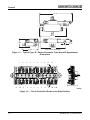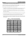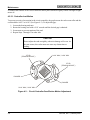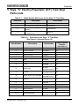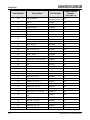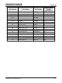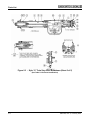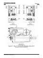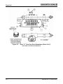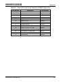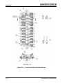
1
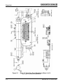
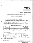
Union Switch & Signal Inc., an Ansaldo Signal company
1000 Technology Drive, Pittsburgh, PA 15219 ● 645 Russell Street, Batesburg, SC 29006
SM 5434
Style “S”
Electro-Pneumatic Train Stop
Part Numbers
N293126
N329366
N329366-001
N329366-002
♦ Installation
♦ Operation
♦ Maintenance
Copyright © 2007
Union Switch & Signal Inc.
SM 5434, Rev. 3, February 2007
Proprietary Notice
This document and its contents are the property of Union Switch & Signal Inc. (hereinafter US&S).
This document has been furnished to you on the following conditions: no right or license under any
patents or any other proprietary right in respect of this document or its content is given or waived in
supplying this document. This document or its content is not to be used or treated in any manner
inconsistent with the rights of US&S, or to its detriment, and are not to be copied, reproduced,
disclosed to others, or transferred without the prior written consent of US&S.
Important Notice
US&S constantly strives to improve our products and keep our customers apprised of changes in
technology. Following the recommendations contained in the attached service manual will provide
our customers with optimum operational reliability. The data contained herein purports solely to
describe the product, and does not create any warranties.
Within the scope of the attached manual, it is impossible to take into account every eventuality that
may arise with technical equipment in service. Please consult your local US&S Account Executive
in the event of any irregularities with our product.
We expressly disclaim liability resulting from any improper handling or use of our equipment, even
if these instructions contain no specific indication in this respect. We strongly recommend that only
approved US&S spare parts be used as replacements.
SM 5434, Rev. 3, February 2007
i
Revision History
Revision History
Rev.
Date
Nature of Revision
Original
April 1997
Original Issue
1
April 2003
Incorporated ECO 139712-138. Section 4.2.1.1, dealing with
contact spring adjustment, was revised.
Incorporated ECO 139712-176. New installation figures and
associated parts list were added (Figures 2-1 through 2-4). New
illustration was added to show lube points (Figures 4-1 and 4-2).
Parts lists and illustrations in Appendix A were all updated. Format
and editorial changes were made.
ii
2
May 2005
Incorporated ECO CRS01319. Added new pre-bent contacts to the
circuit controller and revised the tolerances on controller
adjustments. Updated the parts list.
3
February 2007
Incorporate ECO EM2355. Removed Part Numbers N330549 and
N3305490001 from this manual and made changes associated with
removing these two part numbers.
SM 5434, Rev. 3, February 2007
Table of Contents
Table of Contents
1
General....................................................................................................................................................................... 1-1
1.1
Description......................................................................................................................................... 1-1
1.1.1 Operating Mechanism ............................................................................................................... 1-1
1.1.2 Circuit Controller ....................................................................................................................... 1-1
1.2
Specifications .................................................................................................................................... 1-1
2
Installation................................................................................................................................................................. 2-1
2.1
General.............................................................................................................................................. 2-1
2.2
Mounting............................................................................................................................................ 2-1
2.3
Lubrication ......................................................................................................................................... 2-1
3
Operation................................................................................................................................................................... 3-1
3.1
Operating Mechanism ....................................................................................................................... 3-1
3.2
Circuit Controller................................................................................................................................ 3-1
4
Maintenance.............................................................................................................................................................. 4-1
4.1
Field Maintenance ............................................................................................................................. 4-1
4.1.1 Return Spring Compression Adjustment................................................................................... 4-1
4.1.2 Lubrication................................................................................................................................. 4-1
4.2
Shop Maintenance ............................................................................................................................ 4-3
4.2.1 Adjustments............................................................................................................................... 4-3
4.2.2 Inspection and Cleaning............................................................................................................ 4-5
4.2.3 Lubrication................................................................................................................................. 4-5
5
Style “S” Electro-Pneumatic (E.P.) Train Stop Parts Lists................................................................................ 5-1
6
Technical Support.................................................................................................................................................... 6-1
List of Figures
Figure 1-1
Figure 1-2
Figure 2-1
Figure 2-2
Figure 2-3
Figure 2-4
Figure 4-1
Figure 4-2
Figure 4-3
Figure 5-1
Figure 5-2
Figure 5-3
Figure 5-4
Figure 5-5
Figure 5-6
-
Typical Type “S” Electro-Pneumatic Train Stop with Approximate Dimensions .......................... 1-2
Circuit Controller (Shown in the Stop Position) ............................................................................ 1-2
Typical Installation with Short Shaft ............................................................................................. 2-2
Typical Installation with Long Shaft .............................................................................................. 2-3
Typical Installation – Dual Units ................................................................................................... 2-4
Typical Installation – Tripper Arm Details..................................................................................... 2-5
Lubrication Points for the Style “S” Electro-Pneumatic Train Stop .............................................. 4-2
Lubrication Points for the Style “S” Electro-Pneumatic Train Stop .............................................. 4-3
Circuit Controller Cam/Rocker Motion Adjustment....................................................................... 4-6
Style “S” Train Stop Parts Breakdown (Sheet 1 of 5)................................................................... 5-4
Style “S” Train Stop Parts Breakdown (Sheet 2 of 5)................................................................... 5-5
Style “S” Train Stop Parts Breakdown (Sheet 3 of 5)................................................................... 5-6
Style “S” Train Stop Parts Breakdown (Sheet 4 of 5)................................................................... 5-7
Style “S” Train Stop Parts Breakdown (Sheet 5 of 5)................................................................... 5-8
Circuit Controller Parts Breakdown ............................................................................................ 5-10
List of Tables
Table 2-1
Table 4-1
Table 5-1
Table 5-2
Table 5-3
-
Parts Identification for Figure 2-1 through Figure 2-4.................................................................... 2-6
Controller Contact Spring Settings ................................................................................................ 4-4
Model Number References for the Style “S” Train Stop................................................................ 5-1
Parts List for the Style “S” Train Stop ........................................................................................... 5-1
Parts List for the Circuit Controller (N186327) .............................................................................. 5-9
SM 5434, Rev. 3, February 2007
iii
Table of Contents
iv
SM 5434, Rev. 3, February 2007
General
1 General
The Style “S” Electro-Pneumatic Train Stop (Figure 1-1) is a light-weight, rugged device which
controls the position of a lever arm on the rail ties. The lever arm can be positioned to impact the air
release valve on a rail car to dump the brake air pressure system, thus activating the brakes on the train
and causing the train to stop. The Train Stop ensures that a passing train does not continue moving if a
restrictive cab signal aspect is ignored.
The Train Stop is usually provided for left-hand installation with a shaft that allows the tripper arm to
be mounted on either side of the unit.
1.1
Description
1.1.1 Operating Mechanism
The Train Stop uses air pressure working against a helical coil spring to force the tripper arm to the
Clear position. A minimum of 60 psi of air pressure is required to drive the tripper arm to the Clear
position. When air pressure drops to approximately 30 psi the tripper arm will move to the Stop
position. Tripper arm travel is approximately 60°.
The outboard bearing is self-aligning to allow variations in mounting and ensure freedom from
binding. A coupling in the drive shaft is available with spherical bearing surfaces for centering the
drive shaft with the mechanism and to compensate for misalignment.
1.1.2 Circuit Controller
The circuit controller (Figure 1-2) is driven by a pair of rocker arms actuated by a cam on the drive
shaft. The controller has a total of 10 contacts. Two of the contacts (numbers 1 and 10) are always
made indicating Stop or Clear positions.
Of the remaining eight contacts, three (contacts 7 - 9) will be closed and five (contacts 2 - 6) will be
open in the Stop position. In the Clear position this configuration is reversed – contacts 7 - 9 will be
open and contacts 2 - 6 will be closed.
1.2
Specifications
Parameter
Specification
Operating Air Pressure
60 psi min.
Pressure to Achieve Clear Position
55 psi or more
Pressure to Achieve Stop Position
30 psi or less
Tripper Arm Travel
56° to 60°
SM 5434, Rev. 3, February 2007
1-1
General
33-1/2”
28-1/4”
2-1/8”
2-1/8”
26-1/2”
(MTG. HOLE CENTERS)
16-3/4”
Figure 1-1 - Typical Type “S” Electro-Pneumatic Train Stop with Approximate
Dimensions
2
1B
2
3
4
5
6
7
8
5
6
7
8
9
A
10
(D928024)
1
A
1F
3
4
9
10F 10B
SECTION A - A
(928024)
Figure 1-2 - Circuit Controller (Shown in the Stop Position)
1-2
SM 5434, Rev. 3, February 2007
Installation
2 Installation
2.1
General
When installing the train stop, the specific layout drawings should be followed in every detail. See
Figure 2-1 through Figure 2-4 for typical layouts. Please contact the US&S RAIL Team (Section 6) for
specific layout information and customer applications.
NOTE
Figures 2-1 through 2-4 show typical layouts only and are not to be used for
specific installations. For installation details, consult the specific layout
drawings for the specific location of the train stop.
2.2
Mounting
Care should be taken when mounting the outboard bearing (Item 1, Figures 2-1, 2-2, and 2-3) so that
there is no end play in the tripper arm shaft (Item 4, Figures 2-1, 2-2, and 2-3), but not tight enough to
bind the shaft endwise. With the mechanism in the Stop position, the tripper arm (Item 3, Figure 2-4)
shall rest against the stop bracket (Item 19, Figure 2-4) attached to the outboard bearing support. When
the tripper arm is held in the Clear position by the emergency hook (Item 2, Figure 2-4), the contacts
that are closed in the Clear position must be dependably closed.
2.3
Lubrication
The train stops are lubricated at the factory to protect the bearing surfaces during shipment, or for a
limited storage period. Before the unit is placed in service, the cylinder walls should be lubricated
through the lubrication fittings while the stop mechanism is in the full Clear position, using Brake
Cylinder Lubricant US&S Spec. M-7651-2 (Part No. A041353). The same lubricant may be used for
the other bearings that are fitted with lubricating fittings.
SM 5434, Rev. 3, February 2007
2-1
Installation
DIRECTION OF TRAFFIC
5
17
13
11
2 1/8
15
11
MECHANISM
MOUNTING
TIE LENGTHS TO
BE 36” TO 38”
16
2 1/8
5
13
7
9
10
VIEW A
12 1/2
MECH.
MNT'G. TIES,
36" TO 38"
13
7 13
14
4
8
6 1/4 6 1/4
13
1
18
2 1/8
10 1/2
10 1/2
2 1/8
6 1/2
11/2
3
1/8
1 1/2
2 5/8
VIEW A
NOTE: DIMENSIONS ARE IN INCHES
481001
Figure 2-1 - Typical Installation with Short Shaft
(See Table 2-1 for Parts Identification)
2-2
SM 5434, Rev. 3, February 2007
Installation
22 1/2
22 1/2
17
13
5
"A"
22 1/2
11
2 1/8
15
11
16
2 1/8
5
13
7
7 13
C
L OF TRACK
MECHANISM MOUNTING TIE
LENGTHS TO BE 92" TO 94"
14
DIRECTION OF TRAFFIC
9
12 1/2
9
28 1/4
10
4
8
6 1/4 6 1/4
13
1
18
10 1/2
2 1/8
10 1/2
2 1/8
"A"
C
L OF TRACK
6 1/2
1 1/2
3
2 5/8
1/8
1 1/2
SECTION "A-A"
WITH RAMP AND TIE REMOVED
NOTE: DIMENSIONS ARE IN INCHES
481002
Figure 2-2 - Typical Installation with Long Shaft
(See Table 2-1 for Parts Identification)
SM 5434, Rev. 3, February 2007
2-3
Installation
"A"
18
C
L TIE
24
C
L TIE
24
C
L TIE
24
28 1/4
13 3/4
10 3/4
C
L TIE
DIRECTION OF TRAFFIC
17
16
2 1/8
5
13 27
11
11
56 1/2
5
C
L OF TRACK
2 1/8
DIRECTION OF TRAFFIC
7 13 27
10 3/4
13 3/4
28 1/4
27 13 7
SEE VIEW "B"
8
14
15
4
27 13
7 1/2
1
2 1/8
7 1/2
10 1/ 2
10 1/2
2 1/ 8
"A"
26
20
25 24
1 1/2
1 1/2
SECTION "A- A"
WITH RAMP AND TIE REMOVED
NOTE: DIMENSIONS ARE IN INCHES
1/2 TIE PLATE
3
23
21
22
17
VIEW "B"
3/16 ELASTOMER
TIE PAD
3 1/2
3 1/2
4
3
481004
Figure 2-3 - Typical Installation – Dual Units
(See Table 2-1 for Parts Identification)
2-4
SM 5434, Rev. 3, February 2007
Installation
13
3
2
7
6
12 11
10
6
TYPICAL TRIPPER ARM - LONG OR SHORT SHAFT INSTALLATION
2 5/8
1/8
TOP OF RAIL
R
5/8
10
1/2 MIN.
19
36
33 34 35
11/2
30
29
28
32 34 35
31 34 35
ENLARGED VIEW OF TYPICAL TRIPPER ARM - LONG OR SHORT SHAFT INSTALLATION
27 13
7
6 3/4
TOP OF RAIL
2
7
3
9
6
11 11/16 R.
3 1/2
TOP OF RAIL
37
44
28
32 33 34
29
1 1/ 2
6
36
30
42
1/ 2 MIN.
TYPICAL TRIPPER ARM - DUAL UNIT INSTALLATION
31 34 35
ENLARGED VIEW OF TYPICAL TRIPPER ARM - DUAL UNIT INSTALLATION
NOTE: DIMENSIONS ARE IN INCHES
Figure 2-4 - Typical Installation – Tripper Arm Details
(See Table 2-1 for Parts Identification)
SM 5434, Rev. 3, February 2007
2-5
Installation
Table 2-1 - Parts Identification for Figure 2-1 through Figure 2-4
Item
Number
1
2
3
4
Part
Number
Reference
Figure
N433508001
2-1, 2-2
N47900801
2-3
R.H. Hook and Bracket
N47900302
2-4
L.H. Hook and Bracket
N47900701
2-4
N47900501
2-4
N47900401
2-4
M4513714302
2-1
M4513714303
2-2
M47611501
2-3
2-1, 2-2, 2-3
Bearing
Tripper Arm
Shaft Extension
5
Ramp
M186190002
6
Bracket, 1/2 x 1 3/4
M268863
2-4
7
Washer
M171462
2-1, 2-2, 2-3, 2-4
8
Plate, Washer
M312651
2-1, 2-2, 2-3
9
Screw, 5/16 x 2 Hex, Steel
J050045
2-1, 2-2
10
Nut, 5/16 Elas Stop
J048162
2-1, 2-2
11
Screw, 3/4 x 1” Hex Steel
J050123
2-4
12
Washer, 3/4 Lock, Steel
J047772
2-4
13
Screw, 3/4 x 6” Lag
J050347
2-1, 2-2, 2-3 2-4
14
Nipple, 1/4 x 2” Pipe
J328338
2-1, 2-2, 2-3
15
Union, 1/4 Pipe
J0327600112
2-1, 2-2, 2-3
16
Hose, 3/8 Conn
J075211
2-1, 2-2, 2-3
Stop Mechanism
N329366
N293126
N329366002
2-1, 2-2
N329366001
2-3
17
2-6
Description
18
Valve, Electro-Pneumatic
N394324
2-1, 2-2, 2-3
19
Stop Plate
M372920002
2-4
20
Coupling
M159655
2-3
21
Coupling
M163838
2-3
22
Cover
M163740-002
2-3
23
Bolt, 1/2 x 3 3/4 Sq
J046667
2-3
24
Screw, 10-32 x 3/8” Fil Hd
J522019
2-3
25
Washer, No. 10, Lock SS
J4751210109
2-3
26
Fitting – 1610BL Alem Hyd
J039137
2-3
27
Washer, 3/4” Steel
J047506
2-3, 2-4
28
Bearing, Cap and Stand
N178591
2-4
29
Bearing, Bronze Tubing
M155917
2-4
SM 5434, Rev. 3, February 2007
Installation
Item
Number
Description
Part
Number
Reference
Figure
30
Bearing Support
M372925
2-4
31
Bolt, 5/8-11 x 4 Sq Head
J046706
2-4
32
Bolt, 5/8 x 4-1/2 Sq Head
J046708
2-4
33
Bolt, 5/8 x 2-1/4 Sq Head
J046699
2-4
34
Nut, 5/8-11 2B, Hex
J048020
2-4
35
Washer, 5/8 Steel, M1060 75
J047771
2-4
36
Fitting, 1610 Alem Hyd
J039137
2-4
37
Stop Plate
M372920003
2-4
SM 5434, Rev. 3, February 2007
2-7
Installation
2-8
SM 5434, Rev. 3, February 2007
Operation
3 Operation
3.1
Operating Mechanism
Air pressure applied to the cylinder (Item 5, Figure 5-3) exerts a force on the piston (Item 7, Figure
5-3) and thus on the rack (Item 6, Figure 5-3). When this force is sufficient to overcome the coil spring
(Item 13, Figure 5-3), the piston and rack move through the cylinder, thereby compressing the coil
spring until the 3-inch stroke is completed. The coil spring is retained in the end of the spring housing
(Item 4, Figure 5-3) by an adjustable spring retainer (Item 11, Figure 5-3). The teeth of the rack engage
a gear segment (Item 15, Figure 5-3) that is affixed to the shaft (Item 19, Figure 5-2), so the movement
of the rack through the cylinder imparts a rotation of the shaft of approximately 60°. Also attached to
the shaft is a cam (Item 18, Figure 5-2), the rotation of which actuates the rocker arms (Item 23, Figure
5-3), thereby shifting the position of the circuit controller contacts (Figure 1-2).
3.2
Circuit Controller
A stud, affixed to each shifter plate (Items 3 and 4, Figure 5-6), engages the rocker arms (Figure 4-3).
The pivoting action of the rocker arms imparts a lateral movement to the shifter plates. Mounted on the
shifter plates are the spring shifters (Items 5 and 6, Figure 5-6) that engage the moveable contact
spring of each contact set.
The controller has a total of 10 contacts. Two of the contacts (numbers 1 and 10) are always made
indicating Stop or Clear position. Of the remaining eight contacts, three (contacts 7 - 9) will be closed
and five (contacts 2 - 6) will be open in the Stop position. In the Clear position this configuration is
reversed – contacts 7 - 9 will be open and contacts 2 - 6 will be closed.
For a detailed description of the operation of the contacts, refer to Section 4.2.1.
SM 5434, Rev. 3, February 2007
3-1
Operation
3-2
SM 5434, Rev. 3, February 2007
Maintenance
4 Maintenance
4.1
Field Maintenance
4.1.1 Return Spring Compression Adjustment
The adjustment for the return spring is set so that the stop arm starts to clear when approximately 45 psi
air pressure is applied to the piston; it moves to the full Clear position as the air pressure increases to 55
psi. With at least 55-psi air pressure in the cylinder, the stop arm will be in the Clear position.
When the air pressure in the cylinder is less than 55 psi but more than 45 psi, the stop arm should start
moving toward the Stop position. It should reach the Stop position when the air pressure in the cylinder
reaches approximately 30 psi.
Note
Before making any adjustments, the layout and mechanism should
be checked carefully to ensure that there is no binding, excess
friction due to lack of lubrication, or loss of air pressure due to
leakage.
The compression on the return spring can be regulated by adjusting the nut of the spring retainer (Item
11, Figure 5-3) so that the above operating conditions are met.
CAUTION
The spring retainer should never be adjusted so as to expose any of
the threads beyond the outer edge of the spring housing.
4.1.2 Lubrication
Regular and systematic lubricating is recommended at intervals of no more than six months. The period
of time between lubricating depends upon climate, location, and frequency of operation, so it can be
established by experience, but should not extend beyond six months. Refer to Figure 4-1 and Figure 4-2
for the train stop lubrication points.
The cylinder walls are lubricated through the lubricant fittings located on the side of the cylinders,
while the mechanism is in the full Clear position, using Brake Cylinder Lubricant, US&S Spec. M7651-2 (Part No. A041353). A small amount of lubricant may also be added periodically by removing
one of the pipe plugs (Item 37 or 38, Figure 5-2 or Figure 5-3) in the cylinder head, and also through
the plug hole above the rack and segment gear (Item 38, Figure 5-3). The same lubricant may be used
for the other bearings that are fitted with lubricating fittings.
SM 5434, Rev. 3, February 2007
4-1
Maintenance
Light-weight motor oil is recommended for lubricating the circuit controller shifter plates. Several
drops are to be put into the controller at each point indicated in Figure 4-1.
Figure 4-1 - Lubrication Points for the Style “S” Electro-Pneumatic Train Stop
4-2
SM 5434, Rev. 3, February 2007
Maintenance
Figure 4-2 - Lubrication Points for the Style “S” Electro-Pneumatic Train Stop
In addition to lubricating the main train stop assembly, the bearings on the shafts are to be lubricated
with the same lubricant as used on the train stop.
4.2
Shop Maintenance
For certain tests and adjustments, a test rack should be built consisting of two short ties that will give
mounting conditions similar to a typical layout. This should include a removable indicator arm attached
to the extended shaft (Item 4, Figure 2-2) and a dial plate mounted on a bracket also supported on the
ties. The dial is to be calibrated in degrees from 0° (Stop) position to the 60° (Clear) position for the
purpose of checking the stop arm positions, stroke, contact adjustment, etc.
4.2.1 Adjustments
4.2.1.1. Contact Springs
Note
No adjustments are required or recommended to contact spring
N236209 (Long Fingered Contact Springs)
The long-fingered contact springs should be checked to ensure that:
1. All contact spring assemblies shall have a good soldered connection to the block.
2. All contact spring assemblies shall be in the same horizontal plane and in alignment with their
mating springs.
SM 5434, Rev. 3, February 2007
4-3
Maintenance
3. The shifter plates (Items 3 and 4, Figure 5-6) must have completed their movement when the stop
arm has come within 2° of its extreme position at either end of the stroke.
The following adjustments apply to Contact Springs N179246 (Short Fingered Contact Springs). (Refer
to Table 4-1 for a summary of the settings described in the following steps.)
The short-fingered contact springs should be checked to ensure that:
1. Contacts that are closed when the stop arm is in the Stop position, shall open when the stop arm has
reached the 5° to 10° position, with the exception of the number 1F contact (See Figure 1-2).
2. The number 1F contact should remain closed until the stop arm is in the 44° to 47° position, at
which time the contact should be broken and remade on the back contact when and after the stop
arm is in the 52° position.
3. The number 10B contact should be closed when and after the stop arm is in the 10° to 15° position.
4. The contacts that are closed when the arm is in the clear position should remain open to the 48°
position and be dependably closed when and after the stop arm passes the 52° position.
5. Adjust the backstops to rest against the contact springs when the contact is not made. This is a pre-
adjustment and is generally made prior to installation of contact spring N179246 into the train stop
circuit controller.
Table 4-1 - Controller Contact Spring Settings
(Refer to Figure 1-2 for the Contact Spring Positions)
Spring
Position
Closed
Transition
Open
1F
0° to 44°
44° to 47°
48° and Above
1B
Above 52°
48° to 52°
0° to 48°
2
Above 52°
48° to 52°
0° to 48°
3
Above 52°
48° to 52°
0° to 48°
4
Above 52°
48° to 52°
0° to 48°
5
Above 52°
48° to 52°
0° to 48°
6
Above 52°
48° to 52°
0° to 48°
7
0° to 5°
5° to 10°
Above 10°
8
0° to 5°
5° to 10°
Above 10°
9
0° to 5°
5° to 10°
Above 10°
10F
0° to 5°
5° to 10°
Above 10°
10B
15° and
Above
10°to 15°
0° to 10°
Note - 0° corresponds to the “Stop” position on the tripper arm.
4-4
SM 5434, Rev. 3, February 2007
Maintenance
6. There should be 1-1/2 pounds to 3-1/2 pounds of pressure between the contacts when made. This is
accomplished by using a spring bending tool to make slight adjustments to Contact Spring
Assembly N179246 only.
7. Contacts, when adjusted properly, shall maintain a wipe of 1/32” to 3/32” and all similar contacts
shall make and break at approximately the same time.
8. The insulation between all contacts, and between contacts and ground, must withstand a 1000 Vac
ground test.
4.2.1.2. Return Spring Compression
For adjustment of the return spring, refer to Section 4.1.1.
4.2.2 Inspection and Cleaning
All surfaces of air passages and chambers should be thoroughly cleaned. The air cylinders should be
inspected to see that they are free of pits and scores. To remove the piston, the cylinder cap (Item 10,
Figure 5-3) must be removed and a 3/8”-16 bolt must be inserted in the tapped hole in the piston and
then pulled out.
The rocker arms should operate freely and without binding on the cam. The lost motion (play) between
the rocker arm (Item 23, Figure 5-3) and rollers, and the rollers and the cam (Item 18, Figure 5-2),
should be between 0.003” and 0.016”. The shifter plates should slide freely back and forth in the base
plate.
When dismantling for inspection or cleaning, the spring housing (Item 4, Figure 5-3), rack (Item 6,
Figure 5-3), and segment gear (Item 15, Figure 5-3) should be cleaned. When removing the spring and
housing, a 3/4” x 6-1/2” hex head machine bolt (3” thread) and a 3/4” plate washer should be applied
through the spring retainer (Item 11, Figure 5-3) onto the spring rod (Item 12, Figure 5-3).
To clean the circuit controller, dampen a lint-free cloth with an approved degreaser and wipe off any
accumulated dirt from the assembly and the contacts. Clean any accumulations of dirt, etc., from wires
and wire tags. Dry with a clean, lint-free cloth.
Note
If the contact springs or contacts show any signs of pitting,
corrosion or general deterioration, they must be replaced.
4.2.3 Lubrication
All working faces such as cylinder walls, gears, pistons and piston rods are to be given a light coat of
Brake Cylinder Lubricant, US&S Spec. M-7651-2 (Part No. A041353) when assembling. All packing
grooves and lubricating fittings are to be filled under pressure using the same lubricant. (Refer to Figure
4-1 and Figure 4-2 for the lubrication points.) Check to ensure that the rocker arms are accepting grease
when they are lubed. The remaining internal surfaces should be flushed using the same lubricant. All
threads - such as on cylinder heads, piston, and nuts - are to be given a liberal coat of the lubricant
before assembly.
SM 5434, Rev. 3, February 2007
4-5
Maintenance
In addition the bottoms of the circuit controller shifter plates should be lightly coated with light-weight
motor oil.
4.2.3.1. Controller Lost Motion
To prevent excessive lost motion in the circuit controller, the gap between the rocker arm roller and the
cam should be 0.003” to 0.016” (See Figure 4-3). To adjust this gap:
1. Loosen the bearing stud nuts.
2. Rotate the bearing stud with a 9/16'' wrench until the desired gap is obtained.
3. Secure nuts to prevent rotation of the stud.
4. Repeat Steps 1 through 3 for other side.
CAUTION
Do not adjust the stud too tightly, otherwise damage will occur. As
the cam rotates, the rocker must not cause any obstruction or
binding.
STUD
(TENSION ADJUST.)
0.016” MAX., 0.003” MIN.
STUD
(TENSION ADJUST.)
ROCKER
ROCKER
0.016” MAX., 0.003” MIN.
Figure 4-3 - Circuit Controller Cam/Rocker Motion Adjustment
4-6
SM 5434, Rev. 3, February 2007
Parts List
5 Style “S” Electro-Pneumatic (E.P.) Train Stop
Parts Lists
Table 5-1 - Model Number References for the Style “S” Train Stop
Reference
Description
Part Number
A
L.H. with Pipe Plug (55)
N329366
B
L.H. with Pipe Plug (55) and Heater
N329366-001
C
L.H. with Pipe Plug (55) and 2
Heaters
N329366-002*
D
L.H. with Pipe Plug, Cover Chain,
or Shaft Cover
N293126*
Table 5-2 - Parts List for the Style “S” Train Stop
(See Figure 5-1 through Figure 5-5)
Item Number
Description
Part Number
Used on Model
Number
(See Table 5-1)
1
Body, Complete
N186246
All
2
Circuit Controller
PN186327
All
3
Cover
PN186205
All
4
Spring Housing
R269066
All
5
Cylinder
R269067
All
6
Rack
M387688
All
7
Piston, Complete
PN387687
All
7a
Piston
M387592
(Included in Item 7)
All
7b
Packing Nut
M159667
(Included in Item 7)
All
7c
Follower
M182386
(Included in Item 7)
All
7d
Screw, 8-36 x 5/16”, Flat Head
J052071
(Included in Item 7)
All
7e
Packing
J067407
(Included in Item 7)
All
8
Not Used
9
Not Used
10
Cap, Cylinder
M159646
All
11
Spring Retainer
M159647
All
12
Spring Guide Rod, Comp.
PN269081
All
12a
Spring Guide Rod
M269080
(Included in Item 12)
All
SM 5434, Rev. 3, February 2007
5-1
Parts List
Item Number
Description
Part Number
Used on Model
Number
(See Table 5-1)
12b
Spring Retainer
M268941
(Included in Item 12)
All
13
Spring
J068527
All
14
Sleeve
M269029
All
15
Segment Gear
M159648
All
16
Bearing
M159645
All
17
Journal
M159641
All
18
Cam
M269040
All
Shaft
PN186449
A, B, C
Shaft
M212651
D
19
20 – 21
Not Used
22
Stud Bearing
M173206
All
23
Rocker Arm
PN161617
All
24
Bolt, 9/16” Hex Hd
M181972
All
25
Gasket
M162047
All
26
Cable, Outlet
M388563
All
27
Cable, Outlet
M388564
All
28
Screw, 3/8” – 16 x 1/2” Hex
J050049
All
29
Pin
M159741
All
30
Pin
M173217
All
31
Jam Nut
M169406
All
32
Screw
M269041
All
33
Nut, 7/8” Hex
M169407
All
34 – 36
5-2
Not Used
37
Pipe Plug, 1/2” C.I.
J032903
All
38
Pipe Plug, 1/8” Stl. Sq. Hd.
J032900
All
39
Fitting, Lub., 1/8” P.T.
J039155
All
40
Fitting, Lub., 1/8” P.T.
J039137
All
41
Fitting Lub., 1/8” P.T.
J039142
All
42
Screw, 3/8” x 1-1/4”, Hex.
J050056
All
43
Pipe Plug, 1”, C.I., Sq. Hd.
J032907
All
44
Screw, 1/2” - 13 x 1-3/8”, Hex.
Hd.
J050091
All
45
Pipe Thrd. Protector
J032927
All
46
Nut, 3/8” - 16, Hex.
J048009
All
47
Lock Washer, 3/8”, Stl.
J047768
All
48
Pipe Plug, 1/4”, Stl.
J032901
All
49
Reducing Bushing, 1/2” x 1/4”
J032022
All
SM 5434, Rev. 3, February 2007
Parts List
Item Number
Description
Part Number
Used on Model
Number
(See Table 5-1)
50
Lock Washer, 1/2”, Stl.
51 – 53
54 - 55
J047769
All
Not Used
Plug, Black Pipe, 2” C.I.
56 - 58
J032915
All
Not Used
59
Plug, Screw, 5/8” sq.
M385399
All
60
Coupling
M163839
D
61
Bolt, 1/2” x 3-3/4” Sq Head
J046667
D
62
Nut, 1/2”, Steel
J048013
D
63
Lock Washer, 1/2” Stl
J047769
All
64
Washer, 3/8”, Stl. PL.
J047502
All
66
Plate, Mtg.
M451563-7601
B, C
67
Resistor, 800 Ohm
N296580-001
B, C
68
Terminal Strip
J724780
B, C
69
Screw, 6 - 32 x 1/2”, Fil. Hd.
J052244
B, C
70
Lock Washer, #6 Stl.
J475121-0107
B, C
71
Screw, 8 - 32 x 7/8”, Rd. Hd.
J052603
B, C
72
Lock Washer, #8
J047714
B, C
SM 5434, Rev. 3, February 2007
5-3
Parts List
Figure 5-1 - Style “S” Train Stop Parts Breakdown (Sheet 1 of 5)
(See Table 5-2 for Parts Identification)
5-4
SM 5434, Rev. 3, February 2007
Parts List
Figure 5-2 - Style “S” Train Stop Parts Breakdown (Sheet 2 of 5)
(See Table 5-2 for Parts Identification)
SM 5434, Rev. 3, February 2007
5-5
Parts List
Figure 5-3 - Style “S” Train Stop Parts Breakdown (Sheet 3 of 5)
(See Table 5-2 for Parts Identification)
5-6
SM 5434, Rev. 3, February 2007
Parts List
Figure 5-4 - Style “S” Train Stop Parts Breakdown (Sheet 4 of 5)
(See Table 5-2 for Parts Identification)
SM 5434, Rev. 3, February 2007
5-7
Parts List
Figure 5-5 - Style “S” Train Stop Parts Breakdown (Sheet 5 of 5)
(See Table 5-2 for Parts Identification)
5-8
SM 5434, Rev. 3, February 2007
Parts List
Table 5-3 - Parts List for the Circuit Controller (N186327) (Figure 5-6)
Item Number
Description
Part Number
1
Base Plate
M156355
2
Shifter Plate, Comp.
R186340
3
Shifter Plate
R186338
4
Spring Shifter, Molded
J078183
5
Spring Shifter, Molded
J078182
6
Board, Cir. Cont.
N323952
7
Board, Cir. Cont.
N323953
8
Insulation, Micarta
M159663
9
Screw, 14 – 24 x 5/8”, Fil Hd.
J051341
10
Screw, 10 – 32 x 1/2”, Fl. Hd.
J052091
11
Washer
M036073
12
Lock Washer, 1/4”, High Collar
J047521
13
Contact Spring with Straight Backstop
N179246
14
Contact Spring
N236209
SM 5434, Rev. 3, February 2007
5-9
Parts List
Figure 5-6 - Circuit Controller Parts Breakdown
5-10
SM 5434, Rev. 3, February 2007
Technical Support
6 Technical Support
The Rapid Action Information Link Team (RAIL Team) is a group of experienced product and
application engineers ready to assist you to resolve any technical issues concerning this product.
Contact the RAIL Team at 1-800-652-7276 or by e-mail at [email protected].
SM 5434, Rev. 3, February 2007
6-1
Technical Support
6-2
SM 5434, Rev. 3, February 2007