1
INABCCJ
~
An American-Standard Company
SERVICE MANUAL4574·J
OPERATING VALUES FOR 60 HERTZ PV-250 TRACK RELAY
WITH 115 VOLT LOCAL 500 TURN TRACK COIL
N342555-811, 2F-2B CONTACTS
LOCAL 0.165 AMPERE AT 115 VOLTS
* * * * * * * * * * * * * *
Information for adjustment is given in Service Manual 4574.
Check the current operating values using Figure 1 7 of Service Manual 5036 with
15 volts or more at the track transformer secondary. This will insure that the resistance
in series with the track winding is sufficient to provide suitable phase relations. Test
circuit Figure 18 should be used if voltage values are to be checked also. Test circuits
Figures 19 and 20 may be used instead of Figures 17 and 18, but usually they are less
convenient.
·
TABLE I. TEST OPERATING VALUES
Torque
Inch-Grains
Pick Up
Volts
2.3
325
Amos
. 061
Full Stroke
Volts
2. 76
Amps
.075
Min. Drop Away
% of Actual PU
Shoo
90
Field•
80
The above values are 13% higher than ideal and apply to test from single phase supply
with resistance in series with track winding.
It is recommended that relays be taken out of service if the Drop-Away falls below the
•
value shown for field test.
TABLE II. OPERATING VALUES AT IDEAL PHASE RELATIONS
Full Stroke
Pick Up
Volts
Amps
Volts
Amps
Min. Drop Away
% of Actual PU
2.2
2.4
.055
• 062
90
The above values are based on ideal phase relations, track volts lead line volts 90°
and track amperes lead line volts 24°.
June, 1977
B-77-100-1544-2
UNION SWITCH & SIGNAL DIVISION
WESTINGHOUSE AIR BRAKE COMPANY
Swissvale, PA 15218
.i::,.
u,
.
"O
8 ·&---------
L
I
c..i
-~1
3'- ..
-...J
.i::,.
FIGURE 1.
38
1')
- - .
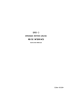
GENERAL
ASSEMBLY FOR
~ \
---
. ·j " .
:z./I'
·· · I . X.1.
~q=ifl)/ 2 •3
PV· 250 RELAY
PC. N342555 ·811
415 ..
· 37·41·42
.. ....
,
.
s
,'
...... • • • • (
81'11 I • • • .
11=
--~
=
')I=
.fol: :
'4)
...........,
,o •
• ' .. ) .
i
• ••
• : • •• .f I I ' • • I
-· ,;.
t
I
:g·
l
,:.l = =
7.::::sc;:t
·:,, = =
12
=
=
c.-;,
't"
~.:::::ic::,t,-
= .,... .....
4·
29
8
..
...'
e
~
WABCO
~
PARTS LIST FOR PV-250 60 HZ. TRACK RELAY
WITH 115V LOCAL 500 TURN TRACK COIL
WITH PIECE NO.
N342555-811
Refer to Figure #1
ITEM NO.
1
2
3
4
5
6
7
8
9
10
11
12
13
14
15
16
17
18
19
20
21
22
23
24
25
26
27
28
29
30
31
32
33
34
35
DESCRIPTION
PART NO.
Frame
Rod Latch
Knob Knurled Th. Nut
Nut Mach.
Latch
Pin S. Stl. Rl. Elas. Stop
Spring Plated
Pin Roll Elas. Stp. Nut
Screw
Cover Bottom J776597
Ser #8-32 x 7/16 Fil. Stl.
T.P.
Gasket Rubber
Ser. 8-32 x 1/4" Rd. Stl.
T. Pl.
Handle
Washer #10 Int. Tooth
Ph. Bz. N. Pl.
Ser. #10-32 x 3/8" Pan Hd.
Calibration Tag
17A (J791665 Adhesive Film)
Wire Seal 2 Ply 12 4LD
SL CTD
Seal Lead
Name Plate M437859
Ser. #4-40 x 3/16" Rd. Stl.
{F) T.P.
Bracket Support
Ser. #10-32 x 1/2" Fl. Stl.
T.P.
Field Control
Field Local
Vane Assembly
Screw Trunnion
Bushing
Bushing Insulation
Roller
Brk. Upper Roller
Brk. Lower Roller
Plate
Lock Bracket
Rivet
M433493
M375913
J770536
M395496
M321728
J048716
M321861
J487087
M321747
M439922
J522042
J047081
J052639
M321821
J047710
J525277
8002036
A043013
J079351
J631005
J525024
M375890
J052091
N436284
N251094
N434594
Nl24889
M232934
M283459
M069693
M397483
Ml61753
M09050.6
Ml09074
J049812
4574-J, p. 3
WABCO
~
PARTS LIST FOR PV-25P 60 HZ. TRACK RELAY WITH 115V LOCAL
500 TURN TRACK COIL WITH PIECE NO. N342555-811
(Continued)
ITEM NO.
36
37
38
39
40
41
42
43
44
45
47
48
49
50
51
4574-J., p. 4
DESCRIPTION
PART NO.
Pin
Washer Tension T.P.
012 x 9/32" OD
Pin
Pin
Pin
Block Terminal
Ser. #8-32 x 7/16
Pin Indexing Elas. Roll Stp.
Parts Bag
Block Contact
See Note "A" -0001
Ser. #8-32 x 7/8" Rd. Hd.
Stl. T.P.
Arm Operating
Counterweight
Counterweight Locknut
Top Cover
M381128
J475104
M381129
M232031
M232935
M433457
J525106
J487090
N349711-3511
N433482
J052603
N390324
M451175-0302
M029956
J776598
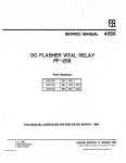
PARTS LIST FOR VANE N-4345,94
USED ON RELAY PV-250 WITH PC. NO. N342555-811
Refer to Figure 2
ITEM NO.
1
2
3
4
5
6
7
8
DESCRIPTION
''
"
'.
.
Vane Crank
Vane
Clips Buffer
Rivets #14 x 5/16" Rd. Hd.
Ph. Bz.
Washer
Rivets #11 x 5/16" Rd. Hd.
Ph. Bz.
Crank RH. Oper. Arm
Rivets #14 x 13/16" Rd. Hd.
Ph. Bz.
"
PART NO.
..
N380677
M231734
Ml30658
J049804
M091997
J049812
M381119
J049819
FIGURE 2.
7·8
3.14
2
VANE
ASSEMBLY
PC. NO. N-434594
4574-J, p. 5
WABCCJ
"'V"A,,I'
-
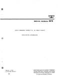
PARTS LIST FOR CONTACT BLOCK
WITH THE FOLLOWING PC. NO'S
N433482
Refer to Figure 3
ITEM NO.
1
2
3
4
5
DESCRIPTION
PART NO.
Spring
Spring
Finger
Spring
Spring
N376007
N376002
M375981
N376006
N376003
Contact
Contact
Contact
Contact
Contact
-
4574-J, p. 6
'•
'"
WABCD
I
"V'A.'V"
f
~
a:
z
I
(\J
m
f'()
m
v
I
~
It)
<(
8
(0
<(
-
0
t0
w
(/)
I0
FIGURE 3.
z
(\J
t; ~ co
v
<to
t-o
ro
f'()
om
(.)
z•
z
...J
v
=m
=
z
·0
t(..)
LaJ
en
0
0
1-MO~--- -
Z-MO!f--
·----t,-MO~
- U--H S-MOQ
ift- Jt- -+i++--9--MO~ ----
---i
o
-.z
~<(
0
f-
(.)
w
tJ')
O
4574-J, p. 7
..
-
PARTS LIST FOR MOUNTING BASE N434647
USED ON RELAY PV-250 WITH PIECE NO .
. N342555-811
Refer to Figure 4
DESCRIPTION
ITEM NO.
Mounting Base Complete
See Note "B"
Mounting Base Only
Tag
Cont. Recpt. Solderless,
#10 to #12 Wire
Cont. Recpt. Solderless,
#14 to #16 Wire
Cont. Recpt. Solderless,
#18 to #20 Wire
Meter Test Plug
Insulated Test Plug (For
Opening any coil or contact
circuit and for removing
receptacle springs)
1
2
3
4
4
4
5
6
NOTE "B"
PART NO.
N434647
N434647-009
J075828
J680181
J680165
J680179
M322965
-
When Mounting Base complete is ordered a
muslin bag of parts 4-1/8" x 5-1/2" is
included in the inner carton with the
mounting base and instruction prints.
Bag Contains:
(2) Tags
(4) #4-40 x 3/16 11 Rd. Hd. Screws
(4) 1/4" Steel plate washers
* (4) 1/4" -20 x 1-1/4 11 Rd. Hd. Stl. Screws
* (4) Washers
* (4) 1/4" Steel Lockwashers
* (4) 1/4" 20 Steel Hex Nuts
and
(Req'd Quantity)
Contact receptacles (solderless) J680165
for #14 to #16 Wire.
If other wire
size is used request the proper part
number as shown in Item 4 when ordering
base complete.
(i.e. N384243 except
using contact receptacles, solderless
J680181).
Asterisk (*) Items are for attaching mounting base to the rack.
4574-J, p. 8
-
•
"'.
WAEJCCJ
~
•
n 11
:a
!'
DD DDD D
DU
nn
nn
II Il
aa
nnnnnn·
~
r-,'
.
ffi
...
·~~t
~
~fJ:
o~>
z,r
.-w~
U)
..... U) -.it
=z
-oo
i.:,
~~~
,.,.._
,<
9'.
• 2 -.it
CD
CM: <t CW)
--0
w -.it
<t O.
CD u,
ii'>>
i~~
-
""o~
.... CD
z
(!)
w
z
Iz
::>
(.)
w
a.
-
0
~
(¥)
0
Q
0
I
.a
!
ii
Jl,
"
DID
D[I
DIC
$j DDJ.
.. II la
DOJ
lo(
8.J
"'
G
I
I·
0
tit
I
0
~
...
Q.
0
0
I
4574-J, p. 9
."
MAINTENANCE NOTICE
PV-250
AC VANE RELAY
Inspection for Loose Counterweights and
Loose Trunnion Screw Locknuts
This Maintenance Notice covers PV-250 ac Vane Relays manufactured from 1984 to Sept. 1988, and
with the following Part Numbers and applicable Service Manuals:
RELAY PART NO.
RELAY MANUAL
N322555-001
N322555-901
SM-4574A
N322555-002
SM-45748
N342555-003
N342555-803
N342555-903
SM-4574C
N322555-004
SM-45740
N322555-005
N322555-805
SM-4574E
N342555-909
N342555-809
SM-4574F
N322555-010
SM-4574G
N322555-007
SM-4574H
N342555-811
SM-4574J
N322555-008
SM-4574L
N342555-812
N342555-813
SM-4574M
N342555-914
SM-4574N
How to find the date of manufacture? Look at the serial number of the relay.
In the serial number to be found on the nameplate of the relay, the first two digits stand for the
week, and the next two digits stand for the year of manufacture of the relay. For example, serial
number 4585115 was made during the 45th week of 1985, and was the 115th item of its
particular part number.
October, 1988
5800 CORPORA TE DRIVE
PITTSBURGH, PA 152Jl
COPYRIGHT 1988, UNION SWITCH & SIGNAL INC
PRINTED IN USA
WARNING
THE FOLLOWING PROCEDURE INVOLVES THE OPENING OF A VITAL RELAY.
THIS PROCEDURE MUST BE PERFORMED BY INDIVIDUALS QUALIFIED TO
WORK ON VITAL RELAYS.
IF THE FOLLOWING INSPECTION IS TO BE DONE IN THE FIELD, BE CERTAIN TO
OBSERVE ALL RULES REGARDING THE SAFE MOVEMENT OF TRAINS BEFORE
REMOVING THE RELAY FROM SERVICE.
Instructions for inspecting for loose counterweights and loose trunnion screw locknuts:
1.
Remove the bottom cover from the relay. This exposes the contact assembly.
Exercise
extreme caution not to disturb the adjustment of the contacts. Remove nameplate to gain
access to the counterweight assembly on the vane crank.
2.
Carefully rotate the vane so that the counterweight assembly is visible. This will reveal one
or more counterweights, with or without a locknut, on the counterweight screw.
3.
As shown in the figure below, check to determine if (a) the counterweight and locknut are
tight, (b) at least two threads are visible on the counterweight screw end, and (c) the split
screw end is slightly spread apart. Tighten any loose counterweights and locknut.
4.
Perform a visual inspection of the relay. Check for rubbing vane, debris inside the relay, and
for obviously misaligned contacts. Check to see that the vane is approximately centered and
that it has the correct amount of end play (0.010 to 0.016 inch). Readjust if required. Check
the vane for freedom of movement. Check to see that the operating arms, clips and
bushings are in their proper position and are free to move. Using a wrench, check the
trunnion locknuts for tightness. Tighten any that are loose.
5.
Perform an electrical calibration test in accordance with the applicable service manual. If the
relay passes the field limit requirements outlined in the service manual, apply glyptal to the
exposed threads of the counterweight screw and the trunnion locknut, as shown in the figure
below. The relay can then be sealed and placed in service.
6.
If the counterweight screw end cannot be spread, or if any of the checks or calibration tests
do not pass, send the relay to US&S Service & Repair in Augusta, Georgia for free-of-charge
service.
~........- - - - - MAKE SURE SPLIT
STUD IS SPREAD
SLIGHTLY APART
REMOVE
NAMEPLATE
COUNTERWEIGHTS
WITHOUT LOCKNUT
COUNTERWEIGHTS
TIGHT AGAINST
EACH OTHER
TWO THREADS
EXPOSED \MIN.)
APPLY GLYPTAL
APPLY
GLYPTAL
HERE
TWO THREADS
EXPOSED \MIN.)
APPLY GLYPTAL
MAKE SURE
TRUNNION
LOCKNUT IS
TIGHT
0
BOTIOM VIEW (COVER REMOVED)
DO NOT DISTURB
CONTACTS
DURING SERVICING
0
COUNTERWEIGHTS
WITH LOCKNUT
MAKE SURE
TRUNNION
LOCKNUT IS
TIGHT