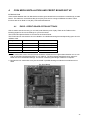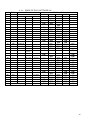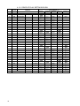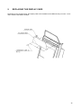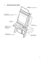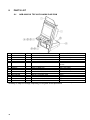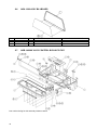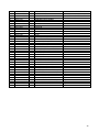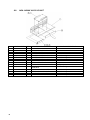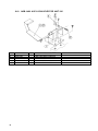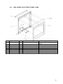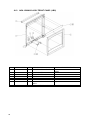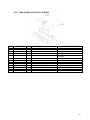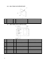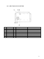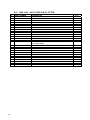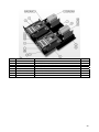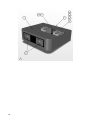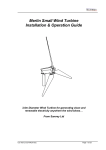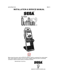
1
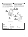
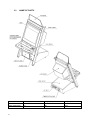
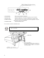
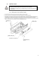
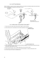
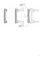
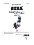
RND-0073
REV 1
SERVICE MANUAL
Incorporating
UPRIGHT TYPE
Before using this product, read this SERVICE MANUAL carefully to understand the
contents stated herein. After reading this manual, be sure to keep it available nearby the
product or somewhere convenient in order to be able to refer to it whenever necessary.
Manufactured in the UK by
CONTENTS
1.
BEFORE USING THIS PRODUCT .......................................................................................................1
INSPECTIONS IMMEDIATELY AFTER TRANSPORTING THE PRODUCT TO THE LOCATION .2
2.
INTRODUCTION TO THIS SERVICE MANUAL ...................................................................................4
3.
INSTALLATION AND MAINTENANCE INSTRUCTIONS .....................................................................5
3.1. HANDLING AND INSTALLATION PRECAUTIONS ..........................................................................5
3.2. COIN HANDLING...............................................................................................................................5
3.3. NAME OF PARTS..............................................................................................................................6
3.4. ACCESSORIES .................................................................................................................................7
3.5. ASSEMBLY INSTRUCTIONS..........................................................................................................10
3.5.1. INSTALLING THE BILLBOARD ...............................................................................................11
3.5.2. SECURING IN PLACE (LEG ADJUSTER ADJUSTMENT) .....................................................12
3.5.3. CONNECTION TO THE POWER SUPPLY .............................................................................13
3.5.4. CREDIT BOARD WIRING TO COIN MECH ............................................................................14
3.6. MOVING THE MACHINE.................................................................................................................15
3.7. INTERNAL SWITCHES AND COIN METERS ................................................................................17
3.8. CONTROL PANEL...........................................................................................................................19
3.8.1. REPLACING THE CONTROL PANEL .....................................................................................19
3.8.2. BUTTON REMOVAL.................................................................................................................20
3.8.3. REPLACING THE INSTRUCTION SHEET ..............................................................................20
3.9. REPLACEMENT OF FLUORESCENT LAMP AND OTHER LAMPS..............................................22
3.9.1. FLUORESCENT LAMP REPLACEMENT ................................................................................22
3.10.
GAME BOARD .............................................................................................................................24
3.10.1.
TAKING OUT THE GAME BOARD.......................................................................................24
3.11.
GAME BOARD POWER SUPPLY VOLTAGE ADJUSTMENT VOLUME ...................................26
3.12.
TROUBLESHOOTING .................................................................................................................27
3.13.
FUSES..........................................................................................................................................28
3.14.
COIN SELECTORS......................................................................................................................29
3.14.1.
COIN CONTROLS SR3 (TOP ENTRY) ................................................................................29
3.14.1.1. TAKING OUT THE COIN MECH.......................................................................................29
3.14.1.2. CLEARING A COIN JAM ..................................................................................................29
3.15.
MAINTENANCE INSTRUCTIONS ...............................................................................................30
3.15.1.
EXPLANATION OF TEST AND DATA DISPLAY .................................................................30
4.
COIN MECH INSTALLATION AND CREDIT BOARD SET UP ..........................................................31
4.1. EXCEL CREDIT BOARD OPTION SETTINGS ...............................................................................31
4.1.1. PRICE OF PLAY SETTINGS UK .............................................................................................33
4.1.2. PRICE OF PLAY SETTINGS EURO........................................................................................34
5.
REPLACING THE DISPLAY CARD ....................................................................................................35
6.
PERIODIC CHECK AND INSPECTION ..............................................................................................36
6.1. CLEANING THE CABINET SURFACES .........................................................................................36
7.
DESIGN RELATED PARTS ................................................................................................................37
8.
PARTS LIST ........................................................................................................................................38
8.1. NOB-0000*UK TOP ASSY NAOMI CABI COM ...............................................................................38
8.2. NOB-100**UK UR CABI TOP ENTRY .............................................................................................39
8.3. NOB-1100UK ASSY FRAMEWORK UR .........................................................................................42
8.4. NOB-1950UK ASSY SFMD WHITE (FLAT DOOR) .......................................................................43
8.5. NOA-1200UK ASSY CRT COVER ..................................................................................................43
8.6. NOA-1300 ASSY BILLBOARD ........................................................................................................44
8.7. NOB-1400UK ASSY CONTROL BOX W/CC EUR..........................................................................44
8.8. NOA-1450UK ASSY I/O UNIT .........................................................................................................46
8.9. NOA-1480UK ASSY COIN MECH..................................................................................................47
8.10.
NOB-1480 ASSY COIN SELECTOR UNIT 220..........................................................................48
8.11.
NOA-1500UK ASSY FRONT PANEL (COM)...............................................................................49
8.12.
NOA-1500HUK ASSY FRONT PANEL (LBG) .............................................................................50
8.13.
NOA-4030UK ASSY ELEC (LBG)................................................................................................51
8.14.
NOA-4010UK ASSY ELEC (NAOMI 2) ........................................................................................52
8.15.
NOA-4010UK ASSY ELEC (NAOMI) ...........................................................................................53
8.16.
NOA-1750UK ASSY SERVICE DOOR ........................................................................................54
8.17.
NOB-1700UK ASSY AC UNIT (Pre 2001) ...................................................................................54
1.1.
ii
NOB-1710UK ASSY AC UNIT NEW ............................................................................................55
8.18.
8.19.
RND-4100UK ASSY XMFR (LBG) ...............................................................................................56
8.20.
NOB-4100UK ASSY XMFR (COM)..............................................................................................56
8.21.
RND-6001UK ASSY WIRE L (LBG).............................................................................................57
8.22.
NOB-6002UK ASSY WIRE R .......................................................................................................57
8.23.
RND-1425 – ASSY CARD R/W (IF FITTED) ...............................................................................58
8.24.
NOB-INST-VT3 ASSY INSTALLATION KIT NOB........................................................................61
9.
APPENDIX A - ELECTRICAL SCHEMATIC .......................................................................................62
9.1. WIRE COLOURS .............................................................................................................................62
9.2. ELECTRICAL SCHEMATIC.............................................................................................................62
iii
1.
BEFORE USING THIS PRODUCT
To ensure the safe usage of the product, be sure to read the following before using the product. The
following instructions are intended for the use of QUALIFIED SERVICE PERSONNEL ONLY. After carefully
reading and sufficiently understanding the instructions should any activity be carried out on the product.
Only qualified service personnel should carry out maintenance on the product.
Terms such as WARNING!, CAUTION, and IMPORTANT! Are used where an explanation is given which
requires special attention, depending on the potential risk. SEGA is not responsible for injury or damage
caused by use in a manner contrary to the instructions stated in this document. In order to prevent
accidents warning stickers and printed instructions are applied in the places where a potentially hazardous
situation relating to the product could arise. Be sure to comply with these warnings.
Indicates that mishandling the product by
disregarding this warning will cause a potentially
hazardous situation which can result in death or
serious injury.
Indicates that mishandling the product by
disregarding this caution will cause a potentially
hazardous situation which can result in personal
injury and or material damage.
This is cautionary information which should be complied with when handling the product. Indicates that
mishandling the product by disregarding this will cause a potentially hazardous situation which may not
result in personal injury but could damage the product.
Be sure to turn off the power and disconnect from the mains supply before working on the machine.
Ensure that the correct fuse(s) is fitted to the machine.
Details of the correct fusing of the machine are enclosed in the Service Manual.
Ensure that only qualified Service Engineers perform any maintenance work on the machine.
Specification changes, removal of equipment, conversion and/or addition, not designated by SEGA are not
permitted and will invalidate this product’s CE conformity.
The parts of the product also include any warning labels or safety covers for personal protection etc. A
potential hazard will be created if the machine is operated while any parts have been removed. Should any
doors, lids or protective covers be damaged or lost, do not operate the product. SEGA is not liable in any
whatsoever for any injury and/or damage caused by specification changes not designated by SEGA.
Before installing the product, check for the Electrical Specification Sticker, SEGA products have a sticker
on which the electrical specifications are detailed. Ensure that the product is compatible with the power
supply voltage and frequency requirements of the location in which the machine is to be installed.
Install and operate the machine only in places where appropriate lighting is available, allowing warning
stickers to be clearly read.
To ensure maximum safety for both customers and operators, stickers and printed instructions describing
potentially hazardous situations are applied to places where accidents could occur. Ensure that where the
product is operated has sufficient lighting to allow any warnings to be read. If any sticker or printed warning
is removed or defaced, do not operate the machine, until it has been replaced by an identical item.
When handling the monitor, be very careful. (Applies only to product with monitor)
Some of the monitor (TV) parts are subject to high tension voltage. Even after turning off the power some
components are still occasionally subject to high tension voltage. Monitor repair and replacement should be
performed by qualified service engineers only.
In cases where commercially available monitors and printers are used only the contents relating to this
product are stated in this manual. Some commercially available equipment has functions and reactions not
stated in this manual. Read this manual in conjunction with the specific manual of such equipment.
Descriptions contained herein may be subject to change without prior notification.
The contents described herein are fully prepared with due care. However, should any question arise or
errors be found please contact SEGA.
1
1.1.
INSPECTIONS IMMEDIATELY AFTER TRANSPORTING THE PRODUCT
TO THE LOCATION
• Inspection should only be carried out by QUALIFIED SERVICE PERSONNEL.
Normally, at the time of shipment, SEGA products are in a state to allowing usage immediately after
transporting to the location. Nevertheless, an irregular situation may arise during transportation preventing
this. Before turning on the power, check the following points to ensure that the product has been
transported safely.
• Are then any dented parts or defects (cuts, etc.) on the external surfaces of the product?
• Are castors and leg adjusters present and undamaged?
• Do the power supply voltage and frequency requirements meet with the local supply?
• Are all wiring connectors correctly and securely connected? Unless connected in the correct direction,
connector connections cannot be made successfully. Do not insert connectors forcibly.
• Are all IC’s of each IC BD firmly inserted?
• Does the power cord have any cuts or dents?
• Do fuses meet the specified rating?
• Are such units such as monitors, control equipment, IC BD, etc. firmly secured?
• Are all earth wires connected?
• Are all accessories available?
• Can all doors and lids be opened with the accessory keys and/or tools?
2
CONCERNING THE STICKER DISPLAY
CONCERNING WARNING STICKERS
SEGA product has stickers describing the product
manufacture number (Serial Number) and
electrical specification. If you require service
assistance you will require the Serial Number.
Identical machines may have different parts fitted
internally. Only by quoting the Serial Number will
the correct parts be identified.
SEGA product has warning displays on
stickers, labels or printed instructions
adhered/attached to or incorporated in the
places where hazardous situations can arise.
The warning displays are intended for the
accident prevention of customers and service
personnel.
SPECIFICATIONS
Installation Space (cm):
76 (W) x 98 (D)
Height (cm):
175
Weight (kg):
Approx. 117
Power, Max: 322W
Rated Voltage (VAC):
230
Rated Current (A):
1.4A – NAOMI
2.0A - LINDBERBH
Operating Temperature Range
5 - 40°C
Note: Descriptions in this manual are subject to change without prior notice.
3
2.
INTRODUCTION TO THIS SERVICE MANUAL
SEGA ENTERPRISES LTD., supported by its experience in electronic high technology of VLSI’s,
microprocessors etc. and with a wealth of experience, have for more than 30 years been supplying various
innovative and popular games to the world market. This Service Manual is intended to provide detailed
descriptions together with all the necessary information covering the general operation of electronic
assemblies, electro-mechanicals, servicing controls, spare parts, etc. as regards ROUTE 66 Standard, a
new SEGA product. This manual is intended for those who have knowledge of electricity and technical
expertise especially in IC’s, CRT’s, microprocessors etc. Carefully read this manual to acquire sufficient
knowledge before working on the machine. Should there be any malfunction, non-technical personnel
should under no circumstances touch the internal systems. Should such a situation arise contact the
nearest branch listed below, or our head office.
SEGA AMUSEMENTS EUROPE LTD./ SEGA SERVICE CENTRE
Suite 3a
Oaks House
12 - 22 West Street
Epsom
Surrey
United Kingdom
KT18 7RG
4
Telephone:
+44 (0) 1372 731820
Fax:
+44 (0) 1372 731849
3.
INSTALLATION AND MAINTENANCE INSTRUCTIONS
• Installation and maintenance should only be carried out by QUALIFIED SERVICE
PERSONNEL.
3.1.
HANDLING AND INSTALLATION PRECAUTIONS
When installing or inspecting the machine, be very careful of the following points and pay attention to
ensure that the player can enjoy the game safely.
The game must NOT be installed under the following conditions:
• Outside, the game is designed for indoor use only.
• In areas directly exposed to sunlight, high humidity, dust, excessive heat or extreme cold.
• In locations that would present an obstacle in the case of an emergency i.e. near fire equipment or
emergency exits.
• On unstable surfaces or surfaces subject to vibration.
• Where liquids, other than routine cleaning, may come into contact with the game.
Important:
• This machine should only be installed by Qualified Service Personnel.
• Be sure to switch the supply power OFF and remove the mains supply plug from the machine before
any work is carried out on the machine.
• Do not attempt to repair the PCB’s (Printed Circuit Boards) yourself. This will void the warranty. The
PCB’s contain static sensitive devices that could be damaged.
• Always return a faulty part to your distributor with adequate packaging and protection.
• When removing the plug from the mains always grasp the plug not the cable.
• Do not use a fuse that does not meet the specified rating.
• Make sure all connections are secure before applying power.
3.2.
•
Ensure that the mains lead is not damaged. If the mains lead is damaged in any
way there could be a danger of electric shock or a fire hazard.
•
Ensure that the power supply is fitted with circuit protection. Using the power
supply without circuit protection is a fire hazard.
COIN HANDLING
Standard Sega machines are fitted with a C120/SR3 coin mechanism, however, as a service to our
customers Sega machines can be supplied with no coin mechanism or door allowing the customer to fit a
coin handling option from the approved list. Fit only the coin handling arrangements detailed below and
follow the instructions provided in section 4. Failure to fit the coin handling options detailed or failure to
follow the installation instructions will render the machine, under the CE marking directive, void.
Approved coin handling options:
• Coin controls C120 and SR3 (Indirect Reject)
• Generic mechanical
• SECI RM4-G20
5
3.3.
NAME OF PARTS
Width (cm)
Length (cm)
Height (cm)
CABINET
76
98
180
When Assembled
76
98
210
6
3.4.
ACCESSORIES
The machine is supplied with an installation kit. Please ensure the following parts are supplied:
No.
1
2
3
7
8
9
101
102
103
106
108
401
402
403
404
405
408
409
410
PART NUMBER
RND-0069
RND-0070
RND-0071
PK0209
OS1019
421-VT3
540-0006-01
540-0015-01
514-5078-5000
509-COIN-NOB
440-CS0186UK
420-6455-02UK
SAECE-XXX
420-5827-PFX
420-6455-MECH
RND-0073
LM1227
LM1246
601-11691
QTY
1
1
1
1
2
2
1
1
1
1
1
1
1
1
1
1
1
1
1
DESCRIPTION
PLAY INST SH VT3 MULTI
SUN INSTR SH VT3
DISPLAY CARD VT3 (ATTACHED TO NOA-1300)
INST KIT BOX NOB COM
SELF SEAL BAG 9X12.3/4
PACKING LABEL
WRENCH M4 TMP PRF
WRENCH M6 TMP PRF
FUSE 5X20 CERAMIC SB 5000MA
SW MICRO COIN ROUTE .250 TAB
STICKER C EPOLEPSY MULTI
SERVICE MANUAL NAOMI LBG
DECLATATION OF CONFORMITY
SERVICE MANUAL SANWA PFX
INSTRUCTION SHEET MECH’L NOB
SERVICE MANUAL VT3
UK MAINS LEAD 10A W/ PLUG
EURO MAINS LEAD 10A
CARTON BOX LBG
THIS BOX ALSO CONTAINS THE BILLBOARD ASSEMBLY (NOA-1300) AND FIXING SCREWS (T00408-OC, QTY 3).
**MONITOR VARIANTS ~ SERVICE MANUAL AS APPROPRIATE.
Items 101 & 102 - Tamperproof TORX wrench.
7
• When returning the GAME BOARD for repair or replacement, be sure to package
the entire ASSY SHIELD CASE in the original card transit box - THERE ARE NO
USER-SERVICEABLE PARTS INSIDE.
• Failure to return the GAME BOARD in this manner may invalidate the warranty.
Note: Game Board packaging may vary
NAOMI
Wrap the ASSY SHIELD CASE with the packaging
material and put it in the original transit box as
shown. Putting it upside down or packing other than
as shown can damage the GAME BOARD and parts.
TRIFORCE
Fold the packing supplies in the order indicated by
the numbers shown in the figure. Package the
SHIELD CASE and place it inside the CARTON
BOX. Packaging the unit in the wrong direction or in
a fashion other than that shown in the figure may
cause damage to the GAME BOARD and/or other
parts.
8
CHIHIRO
1. Wrap the Chihiro Board in a
plastic bag.
2. Place it on top of the bottom
surface cushioning material. Turn
the Filter Board to face the side
with the three honeycomb buffers.
Packing it in the opposite
direction may cause damage to
the Filter Board.
3. Insert corrugated cardboard into
the space between the lateral
honeycomb buffers of the bottom
surface cushioning material and
stow the AVIP cable inside.
4. Place the Chihiro Board wrapped
in the bottom surface cushioning
material into the carton box. Use
the handles on the bottom surface
cushioning material.
5. Place the upper surface
cushioning material on top of the
Chihiro Board. Be sure to align it
in the right direction, as it will not
fit otherwise.
6. Close the top of the carton box
and seal it tightly with adhesive
tape.
LINDBERGH
1. Wrap the LINDBERGH Board in a
plastic bag.
2. Place the LINDBERGH into the
outer packaging and fold around
Game Board as shown.
3. Slide the unit into the carton and
seal.
9
3.5.
ASSEMBLY INSTRUCTIONS
• Perform the assembly by following the procedure herein stated. Failure to comply
with the instructions, for example, inserting the plug into an outlet at a stage not
mentioned in this manual can cause an electric shock
• Assembling should be performed as per this manual. Since this is a complex
machine, erroneous assembling can cause damage to the machine, or
malfunction to occur.
• Do not attempt to complete this work alone, a minimum of 2 people are required.
• Only QUALIFIED SERVICE PERSONNEL should carry out assembly.
When carrying out the assembly work, follow the procedure in the following three item sequence:
STEP 1
INSTALLING THE BILLBOARD
STEP 2
SECURING IN PLACE (LEG ADJUSTER ADJUSTMENT)
STEP 3
CONNECTION TO THE POWER SUPPLY
Note that the parts contained within the installation kit are required for the assembly work.
The following tools will be required when installing this machine:
WRENCH (FOR M4 TAMPERPROOF SCREW)
10
3.5.1. INSTALLING THE BILLBOARD
• Only QUALIFIED SERVICE PERSONNEL should carry out this operation.
1. Insert ASSY BILLBOARD to the top part of the cabinet
2. Secure with the two Tamperproof screws
11
3.5.2. SECURING IN PLACE (LEG ADJUSTER ADJUSTMENT)
• Make sure all of the leg adjusters are in contact with the floor. If they are not the
machine may move and cause injury. This operation requires 2 people.
• This operation should only be carried out by QUALIFIED SERVICE
PERSONNEL.
This machine has four castors and two leg adjusters. When the installation position is decided, unscrew the
leg adjusters so that they raise both front castors 7mm from the floor. Make sure the machine is level.
1. Move the product into the installed position.
2. Unscrew the adjusters until they are in contact
the floor, and use a wrench to turn them further
until the front castors are raised approximately
7mm above the floor.
3. Tighten the locknut on the leg adjusters
upwards to lock the legs in position.
Ensure adequate ventilation is maintained as detailed below:
12
3.5.3. CONNECTION TO THE POWER SUPPLY
• Be sure that the machine is not connected to the mains supply before attempting
this operation
• This operation should only be carried out by QUALIFIED SERVICE
PERSONNEL.
1. The AC Unit is located on the right hand side of the base unit, when viewing the screen (as shown in
section 3.3). It houses the IEC inlet, mains switch and fuse, laid out in one of the following assemblies:
2. Ensure that all of the machine’s wires have been connected in accordance with the preceding sections
and that the mains switch is OFF.
3. Check that the operating voltage of the mains supply matches the machine (section 1.1).
4. Insert the IEC lead into the IEC inlet and the mains plug into a wall socket. If applicable, switch the wall
socket ON.
5. Stand clear of the machine and switch the mains switch ON.
13
3.5.4. CREDIT BOARD WIRING TO COIN MECH
COIN MECH
LOOM
INSTALLATION
C220B
LM1006 OR
LM1006IDC
• Attach one 15way connector to the C220 coin mech.
LM1008
• Attach the blue cable and orange cable to one mech’s microswitch.
(TOP ENTRY)
GENERIC
MECHANICALS
• Attach the other 15 way connector to Validator A on the credit
board.
• Attach the blue/green cable and orange/green cable to the other
mech’s microswitch.
• Attach one 15 way connector to Validator A and the other to
Validator B on the credit board
SECI, C120, SR3
OWN LOOM
• Attach the loom to position A on the credit board
‘EXCEL’ TYPE CREDIT BOARD
14
3.6.
MOVING THE MACHINE
• When moving the machine, be sure to remove the plug from the power supply.
Moving the machine with the plug inserted can cause the power cord to be
damaged, resulting in a fire or electric shock.
• When moving the machine, retract the leg adjusters fully and ensure the casters
make contact with the floor. During movement pay careful attention so that the
casters or leg adjusters do not damage any other cabling laid on the floor. Such
damage could result in a fire or electric shock.
• Do not push the upper part of the cabinet. Failure to observe this can cause the
cabinet to fall forwards and result in accidents.
• When transporting the machine, be sure to hold the catch portion on the rear of
the cabinet with the castors making contact with the surface as shown below.
Inclining the machine by holding portions other than the catch or moving the
cabinet without retracting the adjusters can damage the cabinet and/or the floor
surface.
• Do not push the Billboard. Failure to observe this may damage the installation
portions and may cause unexpected accidents.
• This operation should only be carried out by QUALIFIED SERVICE
PERSONNEL.
15
16
3.7.
INTERNAL SWITCHES AND COIN METERS
• Never touch places other than those specified. Touching places not specified
can cause electric shock and short circuits
• Be careful not to damage wiring. Damaged wiring can cause electric shock and
short circuits.
• Adjust to the optimum sound volume considering the environmental requirements
of the installation location.
The Control Panel Base can be opened by unlocking as shown below. Internal switches can be accessed
when the Base is opened.
17
TEST SWITCH
Push to enter Test Mode of Game BD.
SERVICE SW 1
SERVICE CREDIT SW. Used without registering on the Coin Meter.
SERVICE SW 2
SERVICE CREDIT SW. for 2 players, depending on the specific game.
DEMAG. SWITCH
Removes on-screen colour deviation due to CRT magnetisation. Use this
switch before monitor colour adjustment.
SOUND VOLUME
Adjust the Speaker volume.
The Coin Meter is inside the CASHBOX DOOR.
• If the COIN METER and the Game Board are electrically disconnected, game
play is not possible.
18
3.8.
CONTROL PANEL
• Before starting work, ensure that the cabinet is isolated from the mains by
switching off and removing the IEC mains lead from the wall outlet.
• Be careful not to damage wiring. Damaged wiring can cause electric shock and
short circuits.
3.8.1. REPLACING THE CONTROL PANEL
1. Power OFF the machine and remove the IEC lead from the wall outlet.
2. Unlock the lock on the underside of the Control Panel Base, and open the Panel.
3. There are six connectors on the monitor side in the Base interior. Disconnect all of the six connectors.
Depending on the game used, however, not all of the six connectors mat have been connected.
4. By removing the six sets of Carriage Bolts and Flange Nuts, the Control Panel can be removed from the
Base. At this time, be very careful so as not to damage the wiring.
19
3.8.2. BUTTON REMOVAL
When changing to a game with less Operation Buttons, remove the unnecessary buttons from the Control
Panel and install the Cap Switches to the button cut-outs
3.8.3. REPLACING THE INSTRUCTION SHEET
1. Power OFF the machine and remove the IEC lead from the wall outlet.
2. Unlock the lock on the underside of the Control Panel Base, and open the Panel.
3. While supporting the glass Instruction Cover to prevent it falling out, remove the four screws and clips
on the rear of the Instruction Cover.
4. Remove the Instruction Cover to allow replacement of the Instruction Sheet.
5. Place Instruction Sheet in the recess on the Control Panel Base. Re-fit the Instruction Cover.
6. Fit the four clips and screws as detailed below.
20
21
3.9.
REPLACEMENT OF FLUORESCENT LAMP AND OTHER LAMPS
• Never touch places other than those specified. Touching places other than those
specified can cause electric shock and short circuit. Disconnect the machine from
the supply before attempting the replacement of any lamp.
• When performing work, be sure to turn power off. Working with power on can
cause an electric shock or short circuit.
• Hot fluorescent lamps can cause burns. Be very careful when replacing them.
• Lamps should only be replaced by QUALIFIED SERVICE PERSONNEL.
3.9.1. FLUORESCENT LAMP REPLACEMENT
22
23
3.10. GAME BOARD
• When performing work, be sure to turn power off. Working with power on can
cause an electric shock or short circuit.
• Be careful not to damage wiring. Damaged wiring can cause an electric shock or
short circuit.
• The voltage/amperage ratings for the Game Board are 3.3V 12A, 5.0V 10A and
12V 2A. To avoid risk of fire, never use any board with supply requirements
exceeding the above.
• When replacing the Game Board with one not of JAMMA standard, be sure to
use only the harness supplied by the manufacturer of the Game Board. Using
other harnesses constitutes a fire risk.
In this manual, only NAOMI SHIELD CASE removal is explained. When using other Game Boards such
and LINDBERGH, the removal process is similar whereby all the connections on the face of the Game
Board must be removed before extracting the 2x thumbscrews and pulling out the wooden base.
3.10.1.TAKING OUT THE GAME BOARD
To take out the game board (NAOMI SHIELD CASE), remove together with the wooden base on which the
Game Board is mounted.
1. Turn power OFF by removing the IEC lead from the wall socket.
2. Disconnect all of the connectors connected to the Shield Case Filter Board. Also disconnect all of the
connectors connected to the devices other than the Shield Case on the base. The number of
connectors varies on the specific game.
24
3. Remove the screws securing the wooden Base and remove it from the cabinet together with the Shield
Case, as detailed below. Be careful not to damage wiring during removal.
4. Take out the four screws and remove the Shield Case.
25
3.11. GAME BOARD POWER SUPPLY VOLTAGE ADJUSTMENT VOLUME
• The Voltage Adjustments shown below are factory set and must NOT BE
CHANGED. Changing the setting without a justifiable reason can damage the IC
Board and cause malfunctioning.
26
3.12. TROUBLESHOOTING
• These procedures should only be carried out by QUALIFIED SERVICE
PERSONNEL.
If a problem occurs, first check the wiring connections.
PROBLEMS
CAUSE
COUNTERMEASURES
When the main
switch is turned ON,
the machine is not
activated
The power is not ON.
Firmly insert the plug into the outlet.
Incorrect power source/voltage.
Make sure that the power supply/voltage
are correct.
AC Unit CIRCUIT PROTECTION
DEVICE (ie; fuse) was activated due to
an instantaneous overcurrent.
First, remove the cause of overcurrent
and reinstate the circuit protection device
to its original status.
Then identify the cause of the fault on the
item which caused the overcurrent & fix.
The colour image on
Incorrect monitor adjustment.
Make appropriate adjustments. Refer to
the Monitor Service Manual supplied with
this product.
The on-screen image
of the monitor sways
and/or shrinks
The power source and voltage are not
correct.
Make sure that the power supply and
voltage are correct.
Sound is not emitted
Sound volume adjustment is not
correct.
Adjust the volume setting on the VTS
bracket. Refer to the Monitor Service
Manual supplied with this product.
Malfunctioning BD and Amp.
Perform Sound Test to check it. Refer to
the Monitor Service Manual supplied with
this product.
Connector connection is incorrect
Check connector connection from Base to
Speaker
Fluorescent lamp needs replacement
Replace the fluorescent lamp. Refer to the
Monitor Service Manual supplied with this
product.
The connector is disconnected
Check connector connections in the
billboard case. Refer to the Monitor
Service Manual supplied with this product.
the screen is
incorrect
The fluorescent lamp
does not light up
27
3.13. FUSES
• Never touch places other than those specified. Touching places other than those
specified can cause electric shock and short circuit. Disconnect the machine from
the supply before attempting the replacement of any fuse.
• FUSES should only be replaced by QUALIFIED SERVICE PERSONNEL.
• Only replace fuses with ones of the same value and type.
There are a number of fuses used on this machine to protect the user and the machine from damage. Only
replace the fuse once you have removed the cause of its failure. Detailed below is a list of the fuses used,
their location and if relevant PCB reference:
PART NUMBER
514-5078-3150
514-5078-6300
514-5078-10000
514-5078-6300
LOCATION
STEREO AMP REF. F1, F2
SWITCH REG REF. F1
IEC INLET REF. F1
CONN. BD. REF. F1
TYPE & DETAILS
5x20mm CERAMIC SB 3.15A
5x20mm CERAMIC SB 6.3A
5x20mm CERAMIC SB 10A
5x20mm CERAMIC SB 6.3A
QTY
2
1
1
1
There are also fuses located on the Monitor PCB. Refer to the relevant Monitor manual supplied to
reference these fuses.
28
3.14. COIN SELECTORS
• Before starting work, ensure that the cabinet is isolated from the mains by
switching off and removing the IEC mains lead from the wall outlet.
• Be careful not to damage wiring. Damaged wiring can cause electric shock and
short circuits.
3.14.1.COIN CONTROLS SR3 (TOP ENTRY)
3.14.1.1. TAKING OUT THE COIN MECH.
Open the Control Panel Base to gain access to the Coin Selector, located on the right-hand side inside the
Control Panel. Lift the clamp on the top of the Selector, and remove the Selector by pulling out diagonally
upward.
3.14.1.2. CLEARING A COIN JAM
If a coin is not rejected when the REJECT button is pressed, open the Control Panel Base as described
previously and open the Selector Gate. After removing the jammed coin, put a normal coin in and check to
see that the Selector functions correctly.
29
3.15. MAINTENANCE INSTRUCTIONS
3.15.1.EXPLANATION OF TEST AND DATA DISPLAY
Use the switches on the VTS to enter the TEST MODE. This will allow you to carry out post installation and
periodic checks and adjustments. The following section details the function of each of the tests:
• Be very careful about entering TEST MODE. If the machine you wish to test is
linked to other machines, exiting test on your machine will cause a network check
to be carried out. This will disable all other machines linked to it.
ITEM
DESCRIPTION
INTERVAL
INSTALLATION OF
THE MACHINE
When the machine is installed perform the following checks:
Monthly
• Check to see that each setting is as per the standard
settings input at the time of shipment.
• In the INPUT TEST mode, check each switch and V.R.
• In the OUTPUT TEST mode, check each of the lamps.
• In the MEMORY TEST mode check all of the IC’s on the
IC BD.
MEMORY
• On the TEST MENU screen choosing the MEMORY
TEST allows self test to be performed. In this test RAM &
ROM are tested.
Monthly
PERIODIC CHECKS
Periodically perform the following
Monthly
• MEMORY TEST.
• Ascertain each setting.
• In the INPUT TEST mode, test the control devices.
• In the OUTPUT TEST mode, check each of the lamps.
CONTROL SYSTEM
• In the INPUT TEST mode, check each switch and V.R.
Monthly
• Adjust or replace each switch and V.R.
MONITOR
IC BOARD
• In the C.R.T. TEST mode, check to ensure the monitor is
adjusted correctly
Monthly
• Clean screen (switch off machine and remove the plug)
Weekly
MEMORY TEST
Monthly
• In the SOUND TEST mode, check the sound related
ROMs
DATA CHECK
• Check such data as held in the bookkeeping screens,
relating to number and length of plays
Monthly
EXTERIOR
MAINTENANCE
• Clean surfaces
Monthly
COIN MECHANISM
• Check switch operation (if fitted)
30
• Lubricate seat sliders
Monthly
4.
COIN MECH INSTALLATION AND CREDIT BOARD SET UP
INTRODUCTION
Game credits between the Coin Mechanism and the game board for this machine are controlled by a credit
board*. This electronic circuit allows the price of play to be set for a range of different countries. These
functions are set on Dual In Line (DIL) PCB mounted switches.
4.1.
EXCEL CREDIT BOARD OPTION SETTINGS
SW1 is used to set the currency (or coin ratio) and SW3 the price of play. Refer to the Tables on the
following pages for the correct settings for your environment.
The Excel board pictured below is mounted in the Control Panel..
The Excel board is connected to the coin validator via a dedicated wiring harness depending upon the coin
validator used:
Wiring Harness
Validator
LM1006
Coin Controls
(15 way connector)
LM1007
Mars
(13 way connector)
LM1008
Mechanical
See note 2
N/A
NRI
See note 1
Notes
1. If NRI mechanisms are to be used, these should be ordered with the highest denomination coin on coin
path #1 and the lowest denomination on coin path #4. The Excel board should be then be set up for
either the UK or Switzerland settings. A minimum connecting lead length of 600mm is required.
2. Mechanical coin mechanisms may be connected in parallel allowing two identical mechanisms to be
fitted.
The Excel Board
31
Country
UK
UK
UK
Setting
Switch 3 Setting
SW1 SW2 SW3 SW4 SW5 SW6
Coin Controls OFF OFF OFF OFF
C220 Parallel
Coin Controls
C220 Binary
Coin Controls
C220 Binary
Credit Board Mode Settings Switch 3
Coin Validator Programming
COIN1 COIN2
COIN3
COIN4 COIN5 COIN6
£1
50p new
20p
10p
50p old
OFF
OFF
OFF
£1
50p new
20p
10p
-
50p old
-
£2
OFF
ON
OFF
OFF
£1
50p new
20p
10p
-
£2
-
-
£2
-
50p
old
50p
old
-
Coin Controls
SR3 Parallel
ON
ON
OFF
OFF
£1
50p new
20p
10p
UK
Euro
UK
Coin Controls
SR3 Parallel
OFF
OFF
ON
OFF
Mars ME/MS
111 Parallel
NRI Parallel
UK
Parallel
Belgium
Parallel
Holland
Austria SR3 Parallel
Spain Coin Controls
C220 Binary
ON
OFF
ON
OFF
£2
€2
£1
£1
€1
£2
50p new
50¢
20p
20p
20¢
10p
OFF
ON
OFF
ON
OFF
ON
ON
OFF
OFF
ON
ON
ON
OFF
OFF
OFF
OFF
OFF
ON
ON
ON
10p
20Sch
500Pta
20p
50BFr
5NLG
10Sch
200Pta
50p
20BFr
2.5NLG
5Sch
100Pta
£1
5BFr
1NLG
1Sch
50Pta
25Pta
ON
ON
OFF
ON
500Pta
200Pta
100Pta
50Pta
25Pta
OFF
OFF
ON
ON
100Pta
-
OFF
ON
ON
200Es
€1
TBA
25Pta
new
-
-
ON
50Pta
new
100Es
50¢
Spain
Portugal
Euro
SR3/NRI
Parallel
Coin Controls
C220 Parallel
Parallel
COIN8
-
ON
UK
Spain
COIN7
-
TBA
OFF
ON
Channels
50Es
10p
10¢
50p new 50p old
£2
-
-
C120/SR3 Only
COIN9 COIN10 COIN11 COIN12
-
-
-
-
50p old
-
-
-
-
200Pt 50Pta old 25Pta old
old
200Pta
50Pta
old
-
-
25Pta old
-
-
-
50Pta old 25Pta old
-
Please Note
The credit board automatically sets the validator for parallel and binary
operation through an output on pin 8 of the 17 way pinstrip. For the feature
to work it is necessary for the validator interconnecting cable to include at
wire at this position
TBA
OFF Direct Mode
ON 2 channel Mode
Note: These switch settings are under constant review and may change due to world currency updates.
•
Set SW 1 according to the option settings found in the relevant Price of Play Settings Table on the following pages.
•
For Germany (DM), France (Fr) & Switzerland (SFr), use the appropriate existing setting shown above (from another country) that matches the coin ratios programmed into your coin mech.
•
Set SW 3 on the VTS /Excel board as shown in the table above corresponding to the country required.
32 Rev 1Updated:- 23/11/01
Price
1
2
3
4
5
6
7
8
9
10
11
12
13
14
15
16
17
18
19
20
21
22
23
24
25
26
27
28
29
30
31
32
10p
10p
20p
20p
30p
30p
30p
30p
40p
40p
50p
50p
50p
60p
60p
80p
80p
4.1.1. PRICE OF PLAY SETTINGS UK
Bonus
No Bonus
6 = 50p
No Bonus
3 = 50p
No Bonus
1.66 = 50p
2 = 50p
AMLD *
No Bonus
1.25 = 50p
No Bonus
Switch 1
OFF
ON
OFF
6 = £1
12 =£2
4 = £1
4 = £1
3 = £1
8 = £2
£1
No Bonus
£1
£1
£1.50 No Bonus
£1.50
£2
No Bonus
£2
£3
No Bonus
£3
£5
No Bonus
£5
£7.50 No Bonus
£7.50
£10
No Bonus
Free Play
ON
OFF
6 = £2
ON
OFF
3 = £1
6 = £2
3 = £1
2 = £1
6 = £2
5 = £2
2 = £1
4 = £2
No Bonus
No Bonus
1.25 = £1
ON
OFF
ON
OFF
ON
OFF
3 = £2
2 = £2
2.5 = £2
5 = £4
2 = £2
3 = £5
2 = £10
ON
ON
ON
ON
ON
ON
OFF
OFF
OFF
OFF
ON
ON
OFF
OFF
OFF
OFF
ON
ON
ON
ON
ON
ON
ON
ON
Switch 5
OFF
OFF
OFF
OFF
OFF
OFF
OFF
OFF
OFF
OFF
OFF
OFF
OFF
OFF
OFF
OFF
ON
ON
OFF
OFF
OFF
OFF
ON
ON
OFF
OFF
OFF
OFF
OFF
OFF
OFF
OFF
OFF
ON
ON
ON
ON
ON
ON
ON
ON
ON
ON
ON
ON
ON
ON
ON
ON
ON
ON
OFF
OFF
ON
OFF
OFF
ON
ON
ON
ON
OFF
3 = £10
OFF
OFF
Switch 4
OFF
OFF
OFF
OFF
OFF
OFF
OFF
OFF
ON
OFF
OFF
2 = £5
ON
ON
Switch 3
OFF
OFF
OFF
OFF
ON
ON
ON
ON
ON
2=
£1.50
DIL Switch 1
Switch 2
OFF
OFF
OFF
OFF
ON
ON
ON
OFF
OFF
ON
OFF
ON
OFF
ON
ON
ON
ON
ON
ON
OFF
OFF
OFF
OFF
ON
ON
ON
ON
OFF
OFF
OFF
ON
ON
ON
ON
ON
ON
ON
ON
33
4.1.2. PRICE OF PLAY SETTINGS EURO
Price
Bonus
DIL Switch 1
1
2
3
4
5
6
7
8
9
10
11
12
13
14
15
16
17
18
19
20
21
22
23
24
25
26
27
28
29
30
31
32
34
10¢
No Bonus
10¢
6 = 50¢
20¢
No Bonus
20¢
3 = 50¢
6 = €1
30¢
No Bonus
30¢
1.66 = 50¢
4 = €1
30¢
2 = 50¢
4 = €1
30¢
AMLD *
3 = €1
40¢
No Bonus
40¢
1.25 = 50¢
3 = €1
50¢
No Bonus
50¢
3 = €1
50¢
2 = €1
60¢
No Bonus
60¢
2 = €1
80¢
No Bonus
80¢
1.25 = £1 2 = €1.50
€1
No Bonus
€1
3 = €2
€1
2 = €2
€1.50
No Bonus
€1.50
2 = €2
€2
No Bonus
€2
€3
No Bonus
€3
€5
No Bonus
€5
€7.50
No Bonus
€7.50
€10
No Bonus
Free Play
12 =€2
8 = €2
6 = €2
6 = €2
6 = €2
5 = €2
4 = €2
2.5 = €2
5 = €4
3 = €5
Switch 1 Switch 2 Switch 3 Switch 4 Switch 5
OFF
OFF
OFF
OFF
OFF
OFF
OFF
OFF
OFF
ON
OFF
OFF
OFF
OFF
ON
OFF
OFF
OFF
ON
ON
OFF
OFF
OFF
OFF
ON
OFF
OFF
OFF
ON
ON
OFF
OFF
OFF
ON
ON
OFF
OFF
ON
ON
ON
OFF
OFF
OFF
OFF
ON
OFF
OFF
OFF
ON
ON
OFF
OFF
OFF
ON
ON
OFF
OFF
ON
ON
ON
OFF
OFF
OFF
ON
ON
OFF
OFF
ON
ON
ON
OFF
OFF
ON
ON
ON
OFF
ON
ON
ON
ON
OFF
OFF
OFF
OFF
ON
OFF
OFF
OFF
ON
ON
OFF
OFF
OFF
ON
ON
OFF
OFF
ON
ON
ON
OFF
OFF
OFF
ON
ON
ON
OFF
OFF
ON
ON
ON
OFF
2 = €5
ON
OFF
3 = €10
2 = €10
OFF
OFF
ON
ON
ON
OFF
OFF
ON
OFF
ON
OFF
ON
ON
ON
ON
ON
OFF
OFF
OFF
OFF
OFF
ON
ON
ON
ON
ON
ON
ON
ON
ON
ON
ON
ON
OFF
OFF
ON
ON
ON
ON
ON
ON
ON
ON
ON
ON
ON
5.
REPLACING THE DISPLAY CARD
Depending on the specific game, the Display Card to be installed into the Billboard may not exist. In this
case, use the POP SHEET instead.
35
6.
PERIODIC CHECK AND INSPECTION
The items listed below require periodic check and maintenance to retain the performance of the machine
and ensure safe operation:
• Be sure to check annually to see if the power cords are damaged, the plug is
securely inserted and that there is no dust in the interior of the machine or
between the socket and the power cord. Using the product in an unclean
condition may cause a fire or electric shock.
DESCRIPTION
WHAT TO CHECK
INTERVAL
CABINET
Check Adjusters’ contact with surface
Daily
MONITOR
Cleaning CRT face
Weekly
Check settings
Monthly
GAME BD
Setting check
Monthly
CONTROL PANEL
Input test
Monthly
Speaker, sound
Sound test, check volume adjustment
Monthly
COIN SELECTOR
Coin insertion test
Monthly
Cleaning
Tri-Monthly
POWER SUPPLY CORD
Check condition
Annually
INTERIOR
Clean (Do Not use water jet)
Annually
CABINET SURFACE
Clean (Do Not use water jet)
As required
6.1.
CLEANING THE CABINET SURFACES
When the cabinet surfaces are badly soiled, remove stains with a soft cloth dipped in water or chemical
detergent (diluted with water) and squeezed dry. To avoid damaging surface finish, do not use such
solvents as thinner, benzene, etc. (other than ethyl alcohol), abrasives or bleaching agents. DO NOT USE
A WATER JET.
36
7.
DESIGN RELATED PARTS
37
8.
PARTS LIST
8.1.
No.
1
2
3
4
6
NOB-0000*UK TOP ASSY NAOMI CABI COM
PART NUMBER
NOB-000**UK
NOB-INST-***
RND-0068
NOA-***UK
421-7988-91UK
QTY
1
1
1
1
2
DESCRIPTION
ASSY UR CABI TOP ENTRY COM
ASSY INSTALLATION KIT NOB
WOODEN BASE MAIN
ASSY CNTRL PANEL 2L6B ST
STICKER SERIAL NUMBER UK
COMPONENT REFERENCE
[NOT SHOWN]
NEXT TO AC UNIT, INSIDE
C.PNL
[NOT SHOWN]
[NOT SHOWN]
[NOT SHOWN]
7
PK0121
1
POLY COVER 750X1100X1800
8
PK0201
1
PALLET NOB U/R
9
PK0208
1
SLEEVE NOB U/R COM
10
LB1046
1
LABEL TESTED FOR ELEC. SAFETY
201 031-000416-0C
6
M4X16 CRG BLT CRM
(4)-6
202 050-F00400
6
M4 NUT FLG SER PAS
(4)-6
203 032-000425
2
M4X25 BLT WING PAS
(3)-2
204 FX0301
2
M4 WSHR 16OD FLT BZP
(3)-2
205 008-T00412-OC
4
M4X12 MSCR TMP PRF CRM
REAR HATCH - 4
NB: Where an asterisk “*” appears in a part number or description, it indicates that the part or
assembly is subject to change, depending on the game variant purchased.
38
8.2.
NOB-100**UK UR CABI TOP ENTRY
Part number listing for this assembly follows overleaf.
39
No.
PART NUMBER
1
2
3
4
5
6
NOB-1100UK
NOA-1200UK
NOA-1300
NOA-VT3UK
NOA-1500HUK
NOA-4000UK OR
NOB-4010UK OR
NOA-4030UK
NOA-1750UK
NOA-1801UK
NOB-1001UK
NOB-1002UK
NOA-1003
NOA-1004
NOA-1005UK
280-5112 OR
280-6617 OR
280-6643
280-5113
NOA-1006
NOB-1007UK
NOB-1700UK OR
NOB-1710UK
NOA-1008
NOA-1009
NOA-1010UK
NOA-1011
NOA-1116
NOB-4100UK OR
RND-4100UK
NOB-1013
NOB-1117UK
421-7020UK
LB1102
LB1104
NOB-0005UK
200-5827
200-5827-N
200-5927
200-5949
200-5950
390-5695-40-CUK
220-5643UK
390-5695-40-DUK
OS1098
280-A02048-PM
280-A02000-A
280-A01248-PM
280-A01200-A
280-A00900-A
OS1230
601-0460
280-K00600-0W
008-T00625-OC
030-000620-S
000-P00408
7
8
9
10
11
12
13
15
16
18
19
20
22
23
24
25
26
27
28
29
37
41
42
43
101
101
101
101
101
102
103
114
115
116
117
118
119
120
121
122
123
201
202
203
40
QTY
1
1
1
1
1
1
1
1
1
1
1
1
1
DESCRIPTION
ASSY FRAMEWORK UR
ASSY CRT COVER
ASSY BILLBOARD
ASSY CONTROL BOX W/CC EU
ASSY FRONT PANEL
ASSY ELEC NAOMI
ASSY ELEC NAOMI 2
ASSY ELEC LBGH
ASSY SERVICE DOOR
REAR HATCH
FRAME COVER UR R
FRAME COVER UR L
ENDCAP R
ENDCAP L
REAR COVER UPPER
BUSH FOR NANAO MONITOR
4
4
4
1
1
2
2
1
1
1
COMPONENT REFERENCE
FIX DOWN AT TOP ASSY
(101)-4
BUSH FOR SANWA PFX
COLLAR FOR NANAO MONITOR
SCR CAP
COIN CHUTE UR
ASSY AC UNIT
STICKER SIDE
WSHR PLATE
BILLBD HOLDER
FL BRKT
LID COMMUNI PORT
ASSY XFMR
1
ASSY XFMR LBGH
2
STICKER SIDE LINE NOB
1
WATER GUARD CE
2
STICKER CAUTION FORK
5
STICKER DANGEROUS VOLTAG
1
STICKER CAUTION, HOT SUR
1
KICK STRIP
1
ASSY CLR DSPL 29TYPE 31K 100V
1
ASSY CLR DSPL 29TYPE 31K 100V
1
ASSY CLR DSPL 29TYPE 31K 2934
1
ASSY CLR DSPL 29TYPE 31K UK
1
ASSY CLR DSPL 29TYPE 31K 100V
1
FL TRAY 110V 40W (T12)
1
COIN METER SMALL 12V
1
FL TUBE 40W 600L 1.5"DIA
2
CRIMP BELL END SMALL
5
ROUTER TWIST D20 SO4.8 P
4
ROUTER TWIST D20 ADH
12 ROUTER TWIST D12 SO4.8 P
3
ROUTER TWIST D12 ADH
2
ROUTER TWIST D9 ADH
1.18 FOAM STRIP 2mm X 10mm
10 CABLE TIE 100mm
2
DRIVE FASTENER M6 WHITE
14 M6X25 MSCR TMP PRF TH CR
6
M6X20 BLT W/S PAS
2
M4X8 MSCR PAN PAS
(101)-4
(4)-2
AT BACK OF BASE BOX
BASE LID,DOOR,CRT,FL,CP COVERS
FL COVER
OR
OR
OR
OR
CLIP-IN
(103)-2
2X0.59M TO 8
10-(29)
BASE BOX ABOVE COIN DOOR
(2)-6,(5)-4,(13)-4
(4)-4,(19)-2
FL TUBE CLIPS - 2
204
206
208
209
210
211
214
215
216
217
218
219
220
221
301
302
311
313
319
320
321
322
323
008-T00412-OC
050-F00600
008-T00430-0C
030-000630-S
068-651616
000-P00408-W
000-P00416-W
068-652516
050-F00400
050-F00500
010-P00408
060-F00400
000-P00612-W
050-F00500
NOB-6001UK
NOB-6002UK
600-7159-070
600-7009-250
600-9010-44K
NOB-60201UK
600-9070-45K
600-9080-45K
600-9025-56U
35
4
2
4
4
6
4
4
5
3
4
4
1
1
1
1
1
1
1
1
1
1
1
M4X12 MSCR TMP PRF CRM
M6 NUT FLG SER PAS
M4X30 MSCR TMP PRF TH CR
M6X30 SET W/S PAS
M6 WSHR 16OD FLT PAS
M4X8 MSCR POSI PAN W/FS
M4X16 MSCR POSI PAN W/FS
M6 WSHR 25OD FLT PAS
M4 NUT FLG
M5 NUT FLG SER PAS
M4X8 TAPTITE POSI PAN
M4 WSHR FORM A FLT PAS
M6X12 MSCR PAN W/FS PAS
M5 NUT FLG SER PAS
ASSY WIRE L
ASSY WIRE R
WIRE HARN JVS PWR 070CM
ASSY RGB CA D-SUB 15P 25
WIRE HARN EARTH 100mm M4
WIRE HARN FL NOB
WIRE HARN EARTH 700mm M4
WIRE HARN EARTH 800mm M4
WIRE HARN EARTH 250mm M5
(101)-4
TNG STOPPER CP & REAR LID
(27)-4
(27)-4
(25)-2,EARTHS-4
(5)-2,(11)-1,(12)-1
(101)-4
(102)-2,EARTHS-3
FRAME EARTHS - 3
(6)-4
(6)-4
(323)-1
(323)-1
BBOARD HOLDER TO FL BASE
BASE LID TO XFMR
BASE TO RH FRAME (BOTTOM)
MONITOR CHASSIS TO RH FRAME
41
8.3.
NOB-1100UK ASSY FRAMEWORK UR
No.
1
2
3
4
5
6
7
8
PART NUMBER
NOB-1601UK
NOB-1101UK
NOB-1102UK
NOA-1111X
NOA-1112X
NOA-1113
NOA-1114
NOB-1950UK
QTY
1
1
1
1
1
1
1
1
9
11
102
253-5366
NOA-1115UK
601-5699X
1
1
2
103
104
105
201
202
203
204
205
207
208
209
601-10461UK
601-10462UK
220-5575UK
050-F00600
030-000620-S
068-652016
FX0302
000-P00408-W
050-H01600
FAS-200004
FX0398
2
2
1
4
14
6
2
2
2
16
16
42
DESCRIPTION
BASE BOX UK VERSION
MAIN FRAME UR R
MAIN FRAME UR L
LOWER BEAM
UPPER BEAM
HOOF R
HOOF L
ASSY SFMD WHITE (FLAT
DOOR)
CASH BOX
TNG REAR HATCH
LEG ADJUSTER BOLT
M16x75
CASTOR 50 SWIVEL
CASTOR 50 FIXED
LOCK
M6 NUT FLG SER PAS
M6X20 BLT W/S PAS
M6 WSHR 20OD FLT PAS
M5 NUT FLG SER BZP
M4X8 MSCR POSI PAN W/FS
M16 NUT PAS
M6X14 MSCR SKT CAP BNP
M6 WSHR SPR BNP
COMPONENT REFERENCE
FRONT
REAR
(2)-2,(3)-2
(2,3)-3,(4,5)-4
(2)-3,(3)-3
(6)-1,(7)-1
(6)-1,(7)-1
(102)-2
(103,4)-8EA
(103,4)-8EA
8.4.
No.
101
102
104
105
PART NUMBER
220-5725-03
220-5725-04
220-5574UK
PTR-1951UK
8.5.
No.
1
2
3
101
102
103
301
302
NOB-1950UK ASSY SFMD WHITE (FLAT DOOR)
QTY
1
1
1
1
DESCRIPTION
FRAME SINGLE MINI W/O PA
DOOR SINGLE MINI FLAT,NO
LOCK KEYED DIFFERENT
CAM CRANKED 6mm, LENGTH
COMPONENT REFERENCE
CLAMPS & SCREWS IN BAGS
(102)-1
(104)-1
NOA-1200UK ASSY CRT COVER
ITEM NUMBER
NOA-1201UK
NOA-1202
RND-0037
130-5205
000-P00410-W
340042
NOA-60031
NOA-60032
QTY
1
1
0.38
2
8
6
1
1
DESCRIPTION
CRT COVER
SPEAKER BOX
TAPE SPEAKER BOX 2 S
SPEAKER 4OHM 10W 100
M4X10 MSCR PAN W/FS
RIVET BULBEX 3/16 BF
WIRE HARN SPEAKER L
WIRE HARN SPEAKER R
COMPONENT REF
(101)-8,
(2)-6
[NOT SHOWN]
[NOT SHOWN]
43
8.6.
No.
1
2
201
NOA-1300 ASSY BILLBOARD
PART NUMBER
NOA-1301
NOA-1302UK
008-T00408-OC
8.7.
QTY
1
1
3
DESCRIPTION
BILLBOARD PLATE
BILLBOARD SHEET
M4X8 MSCR TMP PRF TH CRM
(2)-3
NOB-1400UK ASSY CONTROL BOX W/CC EUR
Part number listing for this assembly follows overleaf.
44
COMPONENT REFERENCE
No.
1
2
2
3
4
5
6
7
8
9
10
11
12
13
14
15
16
17
18
19
20
21
22
23
25
26
101
102
103
104
105
201
202
203
205
206
207
301
PART NUMBER
NOA-1450UK
NOA-1480UK
NOB-1480UK
NOA-1401
NOA-1402
CQN-1055X
NOA-1403
HOT-1520
HOT-1504
NOA-1404
HOT-1505UK
NOA-1405
NOA-1406X
NOA-1407UK
HOT-1508
NOA-1419
NOA-1420
220-5428UK
250-5043
NOA-1412
NOA-1414
NOA-1415
NOA-1418
421-10064UK
NOB-1417UK
EP1380
220-5575UK
280-A00900-A
280-A01200-A
280-A02000-A
280-L01640-PS
000-P00410-W
FX0212
FX0255
012-P03506-F
000-P00410-W
FX0301
NOB-60101UK
QTY
1
1
1
1
1
1
1
2
2
1
1
1
1
1
1
2
4
1
1
1
1
2
1
1
1
1
1
3
3
3
4
27
2
2
2
1
1
1
DESCRIPTION
ASSY I/O UNIT
ASSY COIN MECH
ASSY COIN ELEC
CONTROL BOX LOWER
CONTROL BOX UPPER
HINGE
SHAFT
LATCH N
LATCH HOLDER
TOR SPRING
LKG TNG
FLAP
REJECT COVER
TRANSIT CHUTE UK
INSTRUCTION COVER
BRKT INST COVER
L WASHER
COIN ENTRY CE
REJECT BUTTON ASSEMBLY
STICKER DENOMI BLANK FOR
LID TRANSIT CHUTE
LOCK BRKT
DUMMY BTN
STICKER I/O UNIT
ACCEPTOR BRKT
CREDIT BOARD EXCEL
LOCK
ROUTER TWIST D9 ADH
ROUTER TWIST D12 ADH
ROUTER TWIST D20 ADH
STANDOFF 16mm 4mm PANEL
M4X10 MSCR POSI PAN W/FS
M6 NUT BZP
M6 WSHR SPR BZP
N6X1/4" S/TAP POSI FLG B
M4X10 MSCR POSI PAN W/FS
M4 WSHR 16OD FLT BZP
WIRE HARN COIN NOB
COMPONENT REFERENCE
C120 / SR3 / 3½” MECH, OR:
C220B
(101)-1
OR NOB-1406
OR NOB-1407
(14)-2
(15)-4
(25)-4
(1,8,21,16)-4,(24)-2,(5)-9
(7)-2
(7)-2
(17)-2
(201)
(22)
45
8.8.
NOA-1450UK ASSY I/O UNIT
No.
1
2
3
101
102
103
104
106
107
201
301
PART NUMBER
NOA-1451UK
837-13551-92
NOA-1117UK
838-13739
280-A02048-PM
280-A01248-PM
280-A00900-A
280-L00940-PM
280-L00709-OS
000-P00320-W
NOA-60021
QTY
1
1
1
1
1
5
2
3
3
7
1
302
303
304
305
NOA-60022UK
NOA-60023
NOA-60024
NOA-60025
1
1
1
1
46
DESCRIPTION
I/O BASE
I/O CONTROL BD FOR JVS
WATER GUARD
SW BD NAOMICABINET
ROUTER TWIST D20 SO4.8 P
ROUTER TWIST D12 SO4.8 P
ROUTER TWIST D9 ADH
STANDOFF 9L 4mm HOLE PAN
STANDOFF 7OD 4ID 9L
M3X20 MSCR POSI PAN W/FS
WIRE HARN ANALOG
CONTROL
WIRE HARN SW CONTROL
WIRE HARN I/O BD PWR
WIRE HARN SPEAKER L
WIRE HARN SPEAKER R
COMPONENT REFERENCE
(1)-1
[NOT SHOWN]
[NOT SHOWN]
[NOT SHOWN]
(MONITOR REMOTE BOARD)-3
(101)-3
(2)-4,(101)-3
[NOT SHOWN]
[NOT SHOWN]
[NOT SHOWN]
[NOT SHOWN]
[NOT SHOWN]
8.9.
No.
1
2
3
4
101
103
104
202
203
204
205
NOA-1480UK ASSY COIN MECH
PART NUMBER
NOA-1481XUK
NOA-1482
NOA-1483
NOA-1484UK
220-5086-AUK
220-5086-CUK
000-F00408
000-P00308
060-S00300
060-L00300
060-F00400
QTY
1
1
1
2
1
2
5
1
1
1
1
DESCRIPTION
BASE COIN SELECTOR
LINK COIN CHUTE
UPPER COIN CHUTE
ADHESIVE INSULATING PAD
MECH CADDY BASE
MECH CLIP
M4X8 MSCR CSK PAS
M3X8 MSCR PAN PAS
M3 WSHR SPR PAS
M3 WSHR LOCK PAS
M4 WSHR FORM A FLT PAS
COMPONENT REFERENCE
(3)-2,(101)-3
(2)-1
(2)-1
(2)-1
(2)-1
47
8.10. NOB-1480 ASSY COIN SELECTOR UNIT 220
No.
1
2
3
201
202
48
PART NUMBER
NOB-1481UK
NOB-1482
NOB-1484
045-0037
000-P00408-W
QTY
1
1
1
1
2
DESCRIPTION
BASE COIN SELECTOR
LINK COIN SELECTOR 220
L HOOK
DIA6 SNAP PIN
M4X8 MSCR PAN W/FS PAS
COMPONENT REFERENCE
(3)-2
8.11. NOA-1500UK ASSY FRONT PANEL (COM)
No.
1
PART NUMBER
NOA-1500UK-S1
QTY
1
DESCRIPTION
ASSY FRONT PANEL NF
3
4
5
6
7
201
202
NOA-1503
NOA-1504UK
NOA-1505
NOA-1506
NOA-1507
000-P00412-W
012-P03516
1
1
1
2
1
5
4
LIGHT COVER
PRISM PLATE
LID GCS
LID VMS
EMBLEM NAOMI
M4X12 MSCR POSI PAN W/FS
N6X5/8" S/TAP PAN PAS
COMPONENT REFERENCE
NOA-1501 + NOA-1502X AS AN
ASSY
CLIP-IN
(5)-5
(4)-4
49
8.12. NOA-1500HUK ASSY FRONT PANEL (LBG)
No.
1
PART NUMBER
NOA-1500UK-01
QTY
1
DESCRIPTION
ASSY FRONT PANEL PF
3
4
5
6
7
201
NOA-1503
NOA-1504UK
NOA-1505
NOA-1506
NOA-1507
000-P00412-W
1
1
1
2
1
5
202
012-P03516
4
LIGHT COVER
PRISM PLATE
LID GCS
LID VMS
EMBLEM NAOMI
M4X12 MSCR POSI PAN
W/FS
N6X5/8" S/TAP PAN PAS
50
COMPONENT REFERENCE
NOA-1501 + NOA-1502-03 AS AN
ASSY
CLIP-IN
(5)-5
(4)-4
8.13. NOA-4030UK ASSY ELEC (LBG)
No.
1
2
101
103
107
108
PART NUMBER
AMK-0162UK
AMK-0163UK
400-5457-01
838-13616-91
280-A02048-PM
601-6231-B095
QTY
1
1
1
1
4
1
DESCRIPTION
ELEC BASE
ELEC BKT
SW REGU ATX
AUDIO POWER AMP 2CH
ROUTER TWIST D20 SO4.8 P
EDGE TRIM NEW TYPE 0.91t
110
111
201
202
303
304
305
306
280-A01248-PM
280-A02000-A
010-P00408
010-P00308
NON-60010UK
NOA-60011UK
NOB-60202UK
NON-60012UK
2
1
4
4
1
1
1
1
ROUTER TWIST D12 SO4.8 P
ROUTER TWIST D20 ADH
M4X8 TAPTITE POSI PAN
M3X8 TAPTITE POSI PAN BZ
WIRE HARN SW REGU INT
WIRE HARN LBG I/O NAOMI
WIRE HARN AUDIO POWER-IN
WH PSU LBG NAOMI UR
COMPONENT REFERENCE
[NOT SHOWN
[NOT SHOWN]
BACK EDGE IN MIDDLE
SHOWN]
[NOT SHOWN]
[NOT
(101)-4
(103)-4
[NOT SHOWN]
[NOT SHOWN]
[NOT SHOWN]
[NOT SHOWN]
51
8.14. NOA-4010UK ASSY ELEC (NAOMI 2)
No.
1
101
103
107
108
PART NUMBER
NOA-4001X
400-5397-01
838-13616
280-A02048-PM
601-6231-B095
QTY
1
1
1
4
1
DESCRIPTION
ELEC BASE
SW REGU FOR JVS
AUDIO POWER AMP 2CH
ROUTER TWIST D20 SO4.8 P
EDGE TRIM NEW TYPE 0.91t
110
111
201
202
303
304
305
306
280-A01248-PM
280-A02000-A
010-P00408
010-P00308
NOB-60013UK
NOA-60014
NOB-60202UK
600-7159-039
2
1
4
4
1
1
1
1
ROUTER TWIST D12 SO4.8 P
ROUTER TWIST D20 ADH
M4X8 TAPTITE POSI PAN
M3X8 TAPTITE POSI PAN BZ
WIRE HARN SW REGU INT
WIRE HARN I/O BD PWR
WIRE HARN AUDIO POWER-IN
WIRE HARN JVS PWR 039CM
52
COMPONENT REFERENCE
[NOT SHOWN]
BACK EDGE IN MIDDLE
SHOWN]
[NOT SHOWN]
(101)-4
(103)-4
[NOT SHOWN]
[NOT SHOWN]
[NOT SHOWN]
[NOT SHOWN]
[NOT
8.15. NOA-4010UK ASSY ELEC (NAOMI)
No.
1
101
103
107
108
PART NUMBER
NOA-4001X
400-5397
838-13616
280-A02048-PM
601-6231-B095
QTY
1
1
1
4
1
DESCRIPTION
ELEC BASE
SW REGU FOR JVS
AUDIO POWER AMP 2CH
ROUTER TWIST D20 SO4.8 P
EDGE TRIM NEW TYPE 0.91t
110
111
201
202
303
304
305
306
280-A01248-PM
280-A02000-A
010-P00408
010-P00308
NOB-60013UK
NOA-60014
NOB-60202UK
600-7159-039
2
1
4
4
1
1
1
1
ROUTER TWIST D12 SO4.8 P
ROUTER TWIST D20 ADH
M4X8 TAPTITE POSI PAN
M3X8 TAPTITE POSI PAN BZ
WIRE HARN SW REGU INT
WIRE HARN I/O BD PWR
WIRE HARN AUDIO POWER-IN
WIRE HARN JVS PWR 039CM
COMPONENT REFERENCE
[NOT SHOWN]
BACK EDGE IN MIDDLE
SHOWN]
[NOT SHOWN]
[NOT
(101)-4
(103)-4
[NOT SHOWN]
[NOT SHOWN]
[NOT SHOWN]
[NOT SHOWN]
53
8.16. NOA-1750UK ASSY SERVICE DOOR
No.
1
2
101
201
PART NUMBER
NOA-1751UK
DP-1167UK
220-5575UK
008-T00430-0C
QTY
1
1
1
1
DESCRIPTION
SERVICE DOOR
TNG LKG UK
LOCK
M4X30 MSCR TMP PRF TH CR
COMPONENT REFERENCE
INSERT HALF WAY SO TNG OPENS
8.17. NOB-1700UK ASSY AC UNIT (Pre 2001)
No.
1
3
4
101
102
105
110
111
201
202
301
302
303
304
305
54
PART NUMBER
NOB-1701UK
LB1096
421-6595-5000-T
SW1021
EP1302
EP1379
310-5029-D508
514-5078-5000
000-P00308-W
050-F00400
NOB-60001UK
NOB-60004UK
600-9030-45K
600-9080-45K
600-9025-44K
QTY
1
1
1
1
1
1
0.05
1
4
2
1
1
1
1
1
DESCRIPTION
AC BRKT
STICKER PROTECTIVE EARTH
STICKER FUSE 5000mA TYPE
SWITCH ROCKER 250V AC
EUROSOCKET FUSED 1OA 250
FILTER EMI 10A ARCOTRONI
HEAT SHRINK SLEEVING 50.
FUSE 5X20 CERAMIC SB 500
M3X8 MSCR POSI PAN W/FS
M4 NUT FLG
WIRE HARN AC BRKT (NOB)
WIRE HARN AC OUT
WIRE HARN EARTH 300mm M4
WIRE HARN EARTH 800mm M4
WIRE HARN EARTH 250mm M4
COMPONENT REFERENCE
NEXT TO EARTH STUD ON INSIDE
NEXT TO IEC INLET ON OUTSIDE
(102)-0.05m
(102)-1
(105)-4
EARTH - 2
AC BRKT TO XFMR
BASE TO RH FRAME (BOTTOM)
AC BRKT TO BASE
8.18. NOB-1710UK ASSY AC UNIT NEW
No.
1
3
4
101
111
201
202
301
303
305
306
PART NUMBER
NOB-1711UK
LB1096
421-6595-5000-T
EP1381
514-5078-5000
000-F00316
050-F00400
NOB-60004UK
600-9030-45K
600-9025-44K
600-9015-4FK
QTY
1
1
1
1
1
2
2
1
1
1
1
DESCRIPTION
AC BRKT NEW
STICKER PROTECTIVE EARTH
STICKER FUSE 5000mA TYPE
FILTER IEC & SW 6A ROXBU
FUSE 5X20 CERAMIC SB 500
M3X16 MSCR CSK PAS
M4 NUT FLG SER PAS
WIRE HARN AC OUT
WIRE HARN EARTH 300mm M4
WIRE HARN EARTH 250mm M4
WIRE HARN EARTH 150mm
COMPONENT REFERENCE
NEXT TO EARTH STUD ON INSIDE
NEXT TO IEC INLET ON OUTSIDE
(102)-1
(101)-2
EARTH - 2
AC BRKT TO XFMR
AC BRKT TO BASE
FILTER TO PRIMARY EARTH POINT
55
8.19. RND-4100UK ASSY XMFR (LBG)
No.
1
3
101
201
202
203
PART NUMBER
RND-4101UK
838-11856CE-02
560-LBGH-02UK
000-P00416-W
068-441616
012-P00325
QTY
1
1
1
4
4
2
DESCRIPTION
XFMR BASE LBG
CONN BD W/FUSE 6.3A CE
XFMR LBG 230-100V/17V
M4X16 MSCR POSI PAN W/FS
M4 WSHR 16OD FLT PAS
N4X1" S/TAP PAN PAS
COMPONENT REFERENCE
(101)-4
(3)-2
8.20. NOB-4100UK ASSY XMFR (COM)
No.
1
3
101
201
202
203
56
PART NUMBER
RND-4101UK
838-11856CE-02
560-LBGH-02UK
000-P00416-W
068-441616
012-P00325
QTY
1
1
1
4
4
2
DESCRIPTION
XFMR BASE LBG
CONN BD W/FUSE 6.3A CE
XFMR LBG 230-100V/17V
M4X16 MSCR POSI PAN W/FS
M4 WSHR 16OD FLT PAS
N4X1" S/TAP PAN PAS
COMPONENT REFERENCE
(101)-4
(3)-2
8.21. RND-6001UK ASSY WIRE L (LBG)
No.
101
201
301
302
303
304
305
306
307
308
309
PART NUMBER
601-0460
280-N01610-0B
NOB-60043
NOB-60044
NOB-60045
NOB-60046
600-7158-0100
600-9075-45K
600-9055-45K
600-7141-250
600-71873000UK
QTY
10
0.4
1
1
1
1
1
1
1
1
1
DESCRIPTION
CABLE TIE 100mm
SLIT HARN WRAP 16mm DIA
WIRE HARN PWR I/O BD
WIRE HARN SOUND VOL
WIRE HARN SPEAKER L
WIRE HARN SPEAKER R
CA AUDIO RCA TO RCA 2CH
WIRE HARN EARTH 750mm M4
WIRE HARN EARTH 550mm M4
CABLE JVS TYPE A-B 250CM
WH SERIAL A
COMPONENT REFERENCE
I/O BASE TO LH FRAME (TOP)
BASE TO LH FRAME (BOTTOM)
(VT3)
8.22. NOB-6002UK ASSY WIRE R
No.
301
PART NUMBER
NOB-60041UK
QTY
1
DESCRIPTION
WIRE HARN AC EXT UK
COMPONENT REFERENCE
57
8.23. RND-1425 – ASSY CARD R/W (IF FITTED)
58
No
1
2
3
4
5
6
7
8
9
10
11
12
101
102
103
PART NUMBER
RND-1403
TBA-1662
TBA-1663
CFB-1664
CFB-1665
CFB-1666
TBA-1667
TBA-1668
TBA-1669
125-5225
440-WS0179-JP
RND-1404
610-0685
370-5161
601-11132-91
104
105
201
202
203
204
205
206
207
208
209
301
839-1233
OS1230
FAS-120001
000-P00410-W
050-H00400
060-S00400
060-F00400
000-P00308-W
FAS-120017
065-E00300
000-P00320-W
600-7324-23UK
DESCRIPTION
RW BASE
RW GUIDE LOWER
RW GUIDE UPPER
ROLLER
SOL BASE
SENSOR BRKT
LOCK ARM
SHAFT
SHAFT GUIDE
TOR SPRING LOCK ARM
STICKER WITH HI TEMP M
BRKT BOARD
SOLENOID UNIT
PHOTO INTERUPTER
IC CARD READER HW210
(NOT SHOWN – FITTED
ON UNDERSIDE)
SERIAL CONVERTER BOARD
(NOT SHOWN)
FOAM STRIP 2MM X 10MM
TAP SCR #2 TH BLK 4X10
M4X10 MSCR PAN W/S PAS
M4 NUT PAS
M4 WASHER SPRING PAS
M4 WASHER FORM A FLT PAS
M3X8 MSCR PAN W/S PAS
TAP SCR #2 TH 3X6
DIA3 E RING
M3X20 MSCR PAN W/S PAS
WH SERIAL CONV BD & RW
(NOT SHOWN)
QTY
1
2
2
2
2
2
2
2
4
2
1
2
2
2
2
2
.25
8
8
8
10
8
8
2
8
2
2
No
1
2
3
6
7
201
202
203
PART NUMBER
RND-1405
RND-1402
RND-1425
CTF-1153UK
421-11873UK
008-T00408-0C
068-441616-0C
060-S00400
DESCRIPTION
RW BOX
PLATE REAR
ASSY TWIN BASE CARD RW
STICKER IC CARD
STICKER CE
M4X8 TMP PRF TH CRM
M4 WSHR 16OD FLT CRM
M4 WSHR SPR PAS
QTY
1
1
1
2
1
8
4
4
59
60
8.24. NOB-INST-VT3 ASSY INSTALLATION KIT NOB
No.
1
2
3
7
8
9
101
102
103
106
108
401
402
403
404
405
408
409
410
PART NUMBER
RND-0069
RND-0070
RND-0071
PK0209
OS1019
421-VT3
540-0006-01
540-0015-01
514-5078-5000
509-COIN-NOB
440-CS0186UK
420-6455-02UK
SAECE-XXX
420-5827-PFX
420-6455-MECH
RND-0073
LM1227
LM1246
601-11691
QTY
1
1
1
1
2
2
1
1
1
1
1
1
1
1
1
1
1
1
1
DESCRIPTION
PLAY INST SH VT3 MULTI
SUN INSTR SH VT3
DISPLAY CARD VT3 (ATTACHED TO NOA-1300)
INST KIT BOX NOB COM
SELF SEAL BAG 9X12.3/4
PACKING LABEL
WRENCH M4 TMP PRF
WRENCH M6 TMP PRF
FUSE 5X20 CERAMIC SB 5000MA
SW MICRO COIN ROUTE .250 TAB
STICKER C EPOLEPSY MULTI
SERVICE MANUAL NAOMI LBG
DECLATATION OF CONFORMITY
SERVICE MANUAL SANWA PFX
INSTRUCTION SHEET MECH’L NOB
SERVICE MANUAL VT3
UK MAINS LEAD 10A W/ PLUG
EURO MAINS LEAD 10A
CARTON BOX LBG
NB: This assembly is non-game specific and is superseded when a dedicated game is shipped. See game
specific manual for full details of installation kit items.
61
9.
APPENDIX A - ELECTRICAL SCHEMATIC
9.1.
WIRE COLOURS
THE WIRE COLOUR CODE IS AS FOLLOWS:
A
B
C
D
E
PINK
SKY BLUE
BROWN
PURPLE
LIGHT GREEN
Wires other than those of any of the colours listed above will be displayed by 2 alphanumeric characters:
1
2
3
4
5
7
8
9
RED
BLUE
YELLOW
GREEN
WHITE
ORANGE
BLACK
GREY
If the right hand side numeral of the code is 0, then the wire will be of a single colour shown by the left hand
side numeral (see the list above).
Note 1: If the right hand side alphanumeric is not 0, that particular wire has a spiral colour code. The left
hand side character shows the base colour and the right hand side one, the spiral colour.
[Example] 51------------- WHITE/RED = WHITE wire with RED stripes
Note 2: The character following the wire colour code indicates the size of the wire.
K:
AWG18, UL1015
L:
AWG20, UL1007
None
AWG22, UL1007
9.2.
ELECTRICAL SCHEMATIC
The following pages contain the electrical schematic for this machine.
62
SEGA AMUSEMENTS EUROPE LTD./ SEGA SERVICE CENTRE
Suite 3a
Oaks House
12 - 22 West Street
Epsom
Surrey
United Kingdom
KT18 7RG
Telephone:
+44 (0) 1372 731820
Fax:
+44 (0) 1372 731849
© SEGA 2002