1
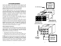
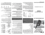
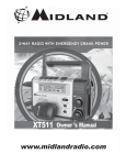
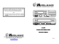
This device complies with part 15 of the FCC rules.
Operation is subject to the following two conditions:
1. This device may not cause harmful interference,
and
MON
A/D
SCAN
AUX
2. This device must accept any interference received,
including interference that may cause undesired
operation.
PWR
/VOL
CH
DN
MENU
UP
MON
A/D
SCAN
AUX
PWR
/VOL
CH
DN
MENU
UP
TITAN™
FM MULTI-MODE MOBILE RADIO
OPERATOR’S MANUAL
1120 CLAY ST • NORTH KANSAS CITY • MISSOURI • 64116
PHONE: (816) 241- 8500 • FAX: (816) 241-5713
www.midlandradio.com
08.2K3
70-2358
FCC RF EXPOSURE REQUIREMENTS
The FCC has adopted a safety standard for human exposure to RF
energy. Proper operation of this radio under normal conditions results
in user exposure to RF energy below the Occupational Safety and
Health Act and Federal Communication Commission limits.
External Speaker
to pins 4 & 6
(required for
Deluxe Head)
Pin 3 Mic Hang-up
Mandatory Safety Instructions to Installers and Users:
This radio is NOT approved for use by the general population in an
uncontrolled environment. This radio is restricted to occupational use
and work related operations only. Radio operators must have the
knowledge to control their exposure conditions and the exposure
conditions of bystanders and/or passengers to satisfy the lower
exposure limit allowed for General Population.
To comply with FCC RF exposure limits, DO NOT operate the
transmitter of this mobile radio when a person outside the vehicle is
within 94 centimeters (38 inches) of the antenna.
The antenna supplied by the manufacturer or radio dealer must be
mounted at a location such that during radio transmission, no person
or persons can come closer than the above indicated minimum safe
distance to the antenna, i.e. 94cm. To comply with current FCC RF
exposure limits, the antenna must be installed at or exceeding the
minimum safe distance stated above, and in accordance with the
requirements of the antenna manufacturer or supplier.
6
7
8
9
10
1
2
3
4
5
Brown jumper wire
between pins 5 & 6
(internal speaker only)
Brown jumper wire
between pins 5 & 6
(internal speaker only)
Vehicle Installation Instructions:
The antenna used for this transmitter must be mounted on the center
of the roof ONLY and must be installed in vehicle having the following
characteristics in order to prevent bystanders and passengers from
being exposed to levels exceeding the limits for General
Population/Uncontrolled Exposure environment:
y
All passengers must be sitting under a solid metal roof.
y
Rooftop width must be at least 76 inches OR the edges of the
physical boundary of the vehicle must be at least 76 inches apart.
DO NOT operate the radio without the proper antenna installed. Do
not substitute any antenna for the one supplied or recommended by
the manufacturer or radio dealer. The antenna gain must not exceed
0 dBd. By not following the antenna recommendations you may be
exposing person(s) to excess radio frequency radiation. You may
contact your radio dealer or the manufacturer for further instructions.
i
3
6
9
12
2
5
8
11
1
4
7
10
70-2358
External Speaker
to pins 4 & 6
(Required for
Deluxe Head)
Pin 3 Mic
Hang-Up (Pin
2 is GND)
8
SERVICE MANUALS
Testing, alignment and service information are provided in the service
manual for this model. Service manuals for Titan™ radios are
available from Midland Radio Corporation at the address shown on
the back cover.
DO NOT transmit more than 50% of total radio use time (50% duty
cycle). Transmitting for more than 50% of the time can cause FCC
RF exposure compliance requirements to be exceeded. This radio is
transmitting whenever the TX icon is displayed on the LCD. Pressing
the PTT switch on the side of the microphone normally causes the
radio to transmit.
Note: The preceding information is provided to make you
aware of RF exposure and how to ensure that this radio is
operated within FCC RF exposure limits.
You, as the qualified end-user of this radio device must control the
exposure conditions of bystanders to ensure the minimum separation
distance, stated above for satisfying FCC RF exposure compliance, is
maintained between the antenna and nearby persons. Transmit only
when all person(s) are at least the minimum distance from the
properly installed, externally mounted antenna.
IMPORTANT SAFETY INFORMATION
CAUTIONS
a The antenna connector must be snugly tightened to maintain
proper electrical connection and moisture resistance.
a Equipment must be grounded according to Midland Radio
Corporation installation instructions for safe operation.
a Equipment should be serviced only by a qualified technician.
a Refer to radio service manual for additional information on
installation and safety precautions.
WARNING!
!
DO NOT allow the antenna to touch or come in very close
proximity with the eyes, face, or any exposed body parts while the
radio is transmitting
!
DO NOT operate the radio in explosive or flammable
atmospheres. The transmitted radio energy could trigger blasting
caps or cause an explosion.
!
DO NOT allow children to operate or play with this radio.
Note: The above warning list is not intended to include all
hazards that may be encountered when using this radio.
7
ii
CONTROLS AND INDICATORS
POWER/VOLUME KNOB
Press and hold for a few seconds for power on. Press and
hold again for power off. Clockwise rotation increases
volume of received messages.
CHANNEL/MENU CONTROL KNOB
Channel Function: Rotate to scroll through channels.
Your radio can be programmed, by the radio
technician to either stop at the highest and lowest
channels, or for channel rollover.
Menu Function: Press and release to activate the
menu mode, which will allow you to access, Squelch
Setting (SQL), Group Setting (GRP), All Group Scan
(AGS) or One Group Scan (OGS), Scan Key Type
Setting (PRI, SCN, P/S), Back Light Control (BLN= on,
or BLF=off), ANI (ANN=on, ANF=off), Clone Mode
(CLN) and Clone Process.
When finished adjusting the squelch, immediately
press the MENU button to cause the new squelch
setting to be stored in the radio memory. For proper
operation the squelch should be set 5 – 10 digits
higher than the level required for initial muting.
All Group Scan availability requires more than 1
group to be programmed and Type A scan selected.
Some scan key types may not
be available
depending on programming. The ANI mode will not
be available unless activated by the radio technician.
PUSH-TO-TALK BAR (On the Hand Microphone)
Transmit mode (talk mode) is initiated when pressed.
The radio will emit your voice signals on the channel
that appears in the Channel Display.
SCAN
PRIORITY SCAN ESCAPE
If the radio technician has programmed the radio for this function, the
operator may press the “AUX” button to operate on the last busy
channel. Press the “AUX” button again to revert to priority scan with
the priority channel unchanged.
NOTE: Conditions when the scan table is automatically reset
(initialized), to original programming, is set by the radio technician.
The user may manually initialize the scan table by pressing the A/D
button for a few seconds (until 2nd beep) when not in scan operation.
ANI OPERATION
1. If ANI operation has been activated during initial programming the
radio will transmit the code on the first transmission of a
conversation.
2. If the ANI is activated on a certain channel by the radio technician,
it cannot be deactivated by the user. The ANI may be set on/off by
the user if it is not specifically activated by the technician.
2 TONE DECODE OPERATION
1. If the radio is programmed for 2 tone decode it may be activated,
on channels so programmed, by pressing and holding the menu
button until the second beep is heard.
2. When the radio receives a call with the proper ANI code a series
of quick beeps will be heard. If the call is answered by pressing
the PTT then the decoder will be reset to normal (non ANI)
operation. If the call is not answered a beep will be heard 15
seconds and 30 seconds after the call and then return to ANI
decode mode.
3. The decoder may be also be deactivated by pressing the MON
button or the PTT button.
SCAN BUTTON
Press SCAN to activate Scan operation. For detailed
information see the following descriptions of the
different scan modes. Also used in conjunction with
the A/D button to add or delete channels from the
scan list.
1
6
4. PRI monitor function is not available in this mode. If scan is
stopped, Add/Delete of Group B channels is available in
Add/Delete mode.
MON
5. Other operation is the same as type “A” scan.
TYPE “B’ ” SCAN MODE (Alt Busy Scan)
1.
Operation is the same as type “B” scan, except the SCAN button
operation is the same as type “A” scan.
2.
If scan is stopped, Add/Delete of Group B channels is available in
Add/Delete mode.
A /D
TYPE “PS” SCAN MODE (Public Safety Scan)
1.
The “A” channels will be scanned in this mode.
2.
The transmit priority and priority monitoring channel will be the
channel that was set when scan was activated.
3.
To change the “PRI 1” channel, rotate the channel selector while
in the scan mode or during OFF HOOK SCAN stop.
4.
Deleting a nuisance channel is the same as type “A” scan.
5.
Adding or deleting the “PRI 2” channel is the same as type “A”
scan.
6.
If scan is stopped, Add/Delete of Group A channels is available in
Add/Delete mode.
TYPE “GRP A” MODE (Scan disabled)
1. Transmit will occur on the currently displayed channel.
2. To change the LAST HOLD CHANNEL rotate the channel selector
during scan.
3. It is not possible to add or delete scan channels.
4. Channel returns to the LAST HOLD CHANNEL, when scan is
stopped by the operator.
5.
AU X
I20
MONITOR BUTTON
Press and immediately release the MON button to
disable the receive Coded Squelch function for
adjustment of squelch and volume and to check for
busy channel. Press and release again to re-enable
the coded squelch. In case the MON button is held
more than 1 second the MON button must be held
again more than 1 second to release the monitor
mode.
A/D BUTTON
Press A/D to activate Add/Delete Mode. For detailed
information see the following description of scan
operation.
AUX BUTTON
Press AUX to access Auxiliary functions
CHANNEL DISPLAY
Indicates selected channel number and is always
illuminated when radio is on. During scan operation,
indicates selected channel or received channel.
DISPATCH OPERATION
SELECTING CHANNELS
If your radio is equipped with more than one channel, rotate the
channel knob to select available channels. Consult your dispatcher for
proper usage.
MESSAGE RECEIPT (RECEIVE)
If a signal exists on the displayed Channel, and you are within radio
range of the sender, you will hear it on the loudspeaker.
Other operation is the same as type “A” scan
TYPE “S CH” MODE (Priority Monitor)
1. If the radio is stopped scanning on the “PRI 1” or “PRI 2” then
transmit will occur on the corresponding “PRI” channel.
2. It is not possible to add or delete scan channels in this mode.
Other operation is the same as type “A” scan.
5
NOTE: Your radio may be equipped to block communications from
radios not in your radio system (coded squelch feature), or it may
even block calls from your system that are not directed to you (select
call feature).
2
NOTES: Squelch level setting can affect scan operation. If scanning
SENDING A MESSAGE (TRANSMIT)
appears slow it may be necessary to adjust the squelch to a
higher level.
The “OFF HOOK SCAN STOP” enable/disable is
programmed by the radio technician prior to use of the radio.
1. Press MON to deactivate the Coded Squelch feature. If your
transceiver is equipped with the Midland Switched Hang-Up Box,
simply lift the hand microphone from the box, instead. If the
selected channel does not use coded squelch, skip this step.
TYPE “A” SCAN MODE (Priority Scan)
2. Listen to make sure the selected Channel is clear.
1.
The radio will scan the “A” scan channels as programmed by the
radio technician or user. To start scan, press and release the scan
button.
2.
The transmit “PRI 1” and priority monitoring channel will be the
channel that was set when starting the scan operation.
3.
In the scan mode, the transmit channel will be the priority channel.
4.
To delete a nuisance channel from the scan list: When the scan
stops on the nuisance channel, press and release the A/D button.
While not in scan mode pressing the A/D button for more than 1
second will reset the scan list.
Channels may be added or deleted from the scan list by pressing the
A/D button then the SCAN button. The A/D icon will appear in the
display when in the A/D mode.
5.
To stop scan, press and release the scan button. To restart scan
when the radio is stopped on a busy channel, rotate the channel
knob up one channel.
When in the A/D mode “SCAN” or “PRI” will appear in the display if
the channel is activated for scan. Pressing the SCAN button will
toggle the channel on/off scan.
6.
If the “OFF HOOK SCAN STOP” is enabled and the microphone
is off hook the “PRI 2” channel add/delete is available. To add or
delete the “PRI 2” channel, select the desired channel then press
and hold the SCAN button more than 1 second. Selection of the
“PRI 2” channel is also possible anytime the radio is not in scan
mode.
7.
If scan is stopped, Add/Delete of Group A channels is available
in Add/Delete mode.
3. Hold the hand microphone close to your mouth, press the PushTo-Talk Bar (PTT) on the hand microphone to initiate transmit,
then announce your message. To hear the replay, release PTT
when finished speaking.
When your conversation is complete, press MON again to engage the
Code Squelch feature, or return the hand microphone to the Switched
Hang-Up Box.
ADD/DELETE CHANNELS FROM SCAN LIST
QUICK GUIDE OF MOBILE SCAN MODES
The radio technician can initially program this radio for one of four
different types of scan. The user can select, through the MENU mode,
up to three variations of the scan programmed by the radio technician.
The following table outlines scan type variation that the user can
obtain depending upon the radio programming.
1. The radio will scan the “B” scan channels as programmed by the
radio technician.
SCAN TYPE PROGRAMMED
NORMAL
USER SELECTION
MODIFIED
SECONDARY
PS
RESULTING SCAN TYPE
PRI (PRI)
A SCAN
A SCAN
S CH MODE
PS PSCAN
SCAN (SCN)
B SCAN
B’ SCAN
B’ SCAN
N/A
PRI SCAN (P/S)
N/A
GRP A
A SCAN
N/A
3
TYPE “B” SCAN MODE (Busy Scan)
2. Transmit will occur on the channel that was last stopped during
scan (hold channel). If there was no hold channel the radio will
transmit on the “PRI 1” channel (channel that was displayed when
scan was started).
3. To return to the hold channel during scan, press and release the
scan button.
4