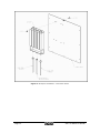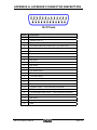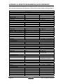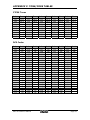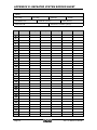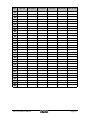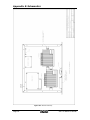
1
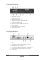
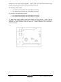
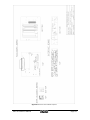
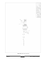
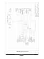
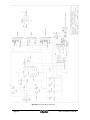
SRC-40 Owner’s Manual Version 3.2, March 2004 Copyright 2004 BY Bridge Embedded Systems, Inc Version 3.2 , March 2004 All rights reserved. Printed in the United States of America. Maxon® name used by Bridge Embedded Systems, Inc. with permission LTR is a registered trademark of EF Johnson Corporation Windows is a registered trademark of Microsoft Corporation For Technical Support, please contact: Midland Radio Corporation 1120 Clay Street North Kansas City, MO 64116 Tel: (816)241-8500 Fax: (816)241-5713 www.midlandradio.com SRC-40 Owner’s Manual Page i TABLE OF CONTENTS CHAPTER 1: INTRODUCTION ........................................................................ 1 Welcome.................................................................................................. 1 Features .................................................................................................. 1 CHAPTER 2: SPECIFICATIONS ...................................................................... 3 General ................................................................................................... 3 Receiver .................................................................................................. 3 Transmitter .............................................................................................. 3 Front Panel Description .............................................................................. 4 Rear Panel Description ............................................................................... 4 CHAPTER 3: INSTALLATION ......................................................................... 5 Standard Accessories................................................................................. 5 Installation............................................................................................... 5 Power Up ................................................................................................. 5 CHAPTER 4: OPERATION .............................................................................. 6 Operating Modes....................................................................................... 6 Channel and User Database ........................................................................ 6 CHAPTER 5: REPEATER MODE....................................................................... 7 Overview ................................................................................................. 7 Operation................................................................................................. 7 Channel Settings....................................................................................... 8 User Settings............................................................................................ 9 Error Alerts .............................................................................................10 CHAPTER 6: BASE STATION MODE.............................................................. 11 Overview ................................................................................................11 Operation................................................................................................11 Base Station Settings ...............................................................................11 CHAPTER 7: AUXILIARY MODE ................................................................... 13 Overview ................................................................................................13 Auxiliary Settings .....................................................................................13 External Controllers ..................................................................................13 CHAPTER 8: REMOTE PROGRAMMING......................................................... 15 Overview ................................................................................................15 Before You Begin .....................................................................................15 Accessing remote program mode................................................................16 Commands..............................................................................................16 Example 1: Add a new user and modify the user’s profile..............................22 Example 2: Deactivate an existing user .......................................................24 CHAPTER 9: ALIGNMENT ............................................................................ 25 Overview ................................................................................................25 Parameters .............................................................................................25 Restoring Factory Default Alignment ...........................................................26 Fine-tuning Transmitter Alignment..............................................................26 CHAPTER 10: KEYPAD LOCK ....................................................................... 28 Overview ................................................................................................28 Page ii SRC-40 Owner’s Manual Procedure ...............................................................................................28 CHAPTER 11: HOT SWAPPING .................................................................... 29 Overview ................................................................................................29 Procedure ...............................................................................................29 CHAPTER 12: DUPLEXER INSTALLATION .................................................... 31 Procedure ...............................................................................................31 APPENDIX A: ACCESSORY CONNECTOR DESCRIPTION ............................... 33 APPENDIX B: REMOTE PROGRAMMING QUICK REFERENCE ........................ 34 APPENDIX C: TONE/CODE TABLES ............................................................. 35 CTCSS Tones...........................................................................................35 DCS Codes ..............................................................................................35 APPENDIX D: REPEATER SYSTEM RECORD SHEET ...................................... 36 APPENDIX E: SCHEMATICS......................................................................... 38 Figure E-2: Overall Connectivity .................................................................39 Figure E-3: DTMF Decoder PCB Install .........................................................40 Figure E-4: Printed Circuit Board Layouts ....................................................41 Figure E-5: DTMF Decoder Schematic..........................................................42 Figure E-6: Accessory Board Schematic.......................................................43 Figure E-7: Interface Board Schematic ........................................................44 Figure E-8: Module to Accessory Board cabling .............................................45 APPENDIX F: 120V AC ~ 240V AC CONVERSION......................................... 46 SRC-40 Owner’s Manual Page iii CHAPTER 1: INTRODUCTION Welcome Thank you for purchasing a Maxon SRC-40 Community Repeater. The SRC-40 is designed to provide you a scalable repeater platform to grow as your system needs grow. The Maxon SRC-40 Series of Community Repeaters integrates the RF power of a fan-cooled 40-watt repeater with the functionality of a high capacity tone panel and a 16 channel base station. You can also disable the internal RF power amp and connect the SRC-40 to an external RF power amp of higher power. In the event you migrate to a trunking system, the SRC-40’s internal controller can be disabled and control surrendered to an external controller such as an LTR controller. This Owner’s Manual will acquaint you with the features and specifications of the SRC-40. It also contains useful information about operating modes and remote programming capabilities of the SRC-40, including step-by-step examples of how to use these features. Every effort has been made in the preparation of this manual to ensure the accuracy of its contents. However, please note that one of the many features of the SRC-40 includes upgradable firmware. Firmware upgrades may modify existing features and/or introduce new features not available at the time of this manual’s publication. Please read the accompanying documentation with any firmware upgrade for any changes to this manual’s content. Features The SRC-40’s many features include: • High Performance Specs: Temperature Compensation Oscillator (TCXO) ensures frequency stability and accuracy during ambient temperature changes. • Modular Design: The modular design of the SRC-40 allows for ease and quick replacement of the internal electronics at the site. • Rack style design: The galvanized steel chassis construction provides for a Heavy Duty housing that can be mounted in a standard 19” rack or desktop configuration. Standard equipped rack handles provide for ease during 19” rack installation. • Internal duplexer (optional): The design of the SRC-40’s chassis allows for an internal duplexer to be installed. • Front panel display and controls: The front panel of the SRC-40 includes a LCD display and four LED status indicators. Front panel controls include a fivebutton keypad and speaker volume control. • Windows-based programmer: The SRC-40 can be setup and maintained using the optional ACC-964CD programming software. Programming is simple and easy – one DB9 cable connects your PC to the SRC-40, no other interface modules are needed. The programmable feature set includes: TX and RX frequencies, TX time-out-timer, and repeater ID update interval. Per user SRC-40 Owner’s Manual Page 1 programmable features include three distinct courtesy tones, tone in tail and hang timer. • Signaling capability: High capacity tone panel supports up to 64 users per channel with 50 CTCSS tones and 112 DCS codes available per channel. Cross tone/code encoding is available as well. • Integrated High-Efficiency Power Supply: The SRC-40 includes an internal power supply with MosFet-based switchmode technology for high reliability, high efficiency and minimum size and weight. It also provides 13.8V output for powering external controllers, thus saving valuable site resources. • 12VDC Forced-Air Cooling Fan: A switch controlled fan cools the TX module when it is actively transmitting. • Variable channel spacing: Each channel can be individually programmed to use 12.5 kHz or 25 kHz spacing. UHF and VHF radios are currently migrating from wide to narrow band spacing to essentially double the number of frequencies available. The migration to narrow band is scheduled by January 1, 2005 for UHF radios and by January 1, 2008 for VHF radios. The SRC-40 can be programmed to use narrow or wide band spacing, making it useful for years to come. • Remote Programming via DTMF tones: In order to save a time consuming trip to the site, the SRC-40 provides for remote programming and maintenance. • Accessory Connector and AUX Feature: The internal tone panel can be disabled and the repeater can be placed in an auxiliary mode where it can then be used as a slave to an external controller. • Air-Time Logging: The SRC-40 automatically logs cumulative airtime on a per use basis. The airtime is recorded in minutes and seconds and is accumulated on per second basis. The air-time data is then retrieved using the ACC-964 programming software. • Keypad Lock: During operation at the site, the keypad can be locked to prevent unwanted tampering with the unit’s settings. • LTR Decoder: When the SRC-40 is connected to an LTR controller, this feature decodes and displays the ID and home channel of the call being repeated. Page 2 SRC-40 Owner’s Manual CHAPTER 2: SPECIFICATIONS General SRC-40U SRC-40V FCC Identifier: F3JSM6450U6 F3JSM6150V2 FCC Compliance: 22,74,80,90,95 22,74,90 Canada: 153 195 653A 3772195714A Weight: 18.5 lbs. 18.5 lbs. Weight w/ duplexer: 19.5 lbs. 19.5 lbs. Frequency Range: 450-480 MHz 148-174 MHz Dimensions (W x H x D): 19.0” x 3.5” x 14.0” 19.0” x 3.5” x 14.0” Frequency Stability: +/- 2.5 ppm +/- 2.5 ppm Receiver SRC-40U SRC-40V Local Oscillator: Low-side injection High-side injection Sensitivity (12 dB SINAD) 0.25 µV @ 12.5 kHz 0.25 µV @25.0 kHz 0.25 µV @ 12.5 kHz 0.25 µV @ 25.0 kHz Selectivity: 62dB @ 12.5kHz 72dB @ 25.0kHz 62dB @ 12.5kHz 72dB @ 25.0kHz Spurious Rejection: 75dB 75dB Intermodulation Rejection: 72dB @ 12.5kHz 72dB @ 25.0kHz 72dB @ 12.5kHz 72dB @ 25.0kHz Antenna Impedance: 50Ω 50Ω Transmitter SRC-40U SRC-40V RF Output (w/o duplexer): 450-470 @ 5-40W 471-480 @ 5-35W 148-174 @ 5-40W Modulation: 160K0F3E, 11K0F3E 160K0F3E, 11K0F3E Maximum Deviation: +/- 5kHz (25 kHz) +/- 2.5 kHz (12.5 kHz) +/- 5kHz (25 kHz) +/- 2.5 kHz (12.5 kHz) FM Hum and Noise 36dB @ 12.5kHz 42dB @ 25.0kHz 36dB @ 12.5kHz 42dB @ 25.0kHz Antenna Impedance: 50Ω 50Ω SRC-40 Owner’s Manual Page 3 Front Panel Description 1) Microphone input jack 2) Volume control knob 3) Alphanumeric and Icon LCD 4) 5 button keypad (▲,▼, BASE, MON, AUX) 5) Computer port DB9 Female 6) LED status indicators (BASE, RX, TONE, TX) 7) Internal Speaker 8) Microphone bracket mounting holes 9) Lighted power switch Rear Panel Description 1) Fan 2) Accessory Port: DB25 female standard on SRC-40 3) Detachable AC cord receptacle 4) TX Antenna N-type female panel mount or duplexer out 5) RX Antenna N-type female panel mount or vacant 6) 13.8V output Page 4 SRC-40 Owner’s Manual CHAPTER 3: INSTALLATION Standard Accessories The following accessories are supplied with the SRC-40. Make sure that all items are present and undamaged: • SRC-40 Community Repeater/Base Station • This SRC-40 Owner’s Manual • Detachable AC-line cord • One strip of four rubber feet The SRC-40 provides 4 mounting holes on the front panel for installation into a 19” rack and 4 rubber feet for placement in a desktop configuration. It is recommended the rubber feet be placed close to the four corners of the bottom of the chassis. If installing the SRC-40 in a 19” rack, use 4 rack screws (not supplied) to securely fasten the SRC-40’s front panel flush with the rack’s rails. Optional accessories include a base station microphone, internal duplexer, and the ACC-964CD programmer. Please check with your dealer for more information about these optional accessories. The SRC-40 is shipped with or without an internal duplexer. If the unit is not equipped with an internal duplexer, there will be an N-type female connector for RX and another for TX located on the rear of the unit. If the unit is shipped with an internal duplexer, there will be one N-type female connector at the TX ANT/Duplexer Out port. Installation The internal power supply of the SRC-40 is factory pre-set for 120V AC 60HZ operation. To convert the internal power supply to 240V AC, see Appendix F. If the SRC-40 did not come with a duplexer installed, connect the received signal to the RX antenna port and connect the TX antenna port’s output to where the powered signal is to be transmitted. If the SRC-40 came installed with a duplexer, attach the antenna cable to the duplexer out port on the rear of the unit. Power Up To power the unit, simply plug the detachable AC-line cord into the receptacle located on the back of the unit and then plug it into an AC line source. Pressing the lighted toggle switch to the up position turns on the SRC-40. The power switch will illuminate indicating the unit is on. The SRC-40 will cycle through a power-up sequence illuminating the LCD and the LED’s. The model name will be displayed for approximately two seconds followed by the version of firmware. If the SRC-40 was ordered without being custom programmed, the default personality will be loaded and WIDELP will be displayed for approximately 2 seconds and then dashed lines. If the unit was ordered custom programmed, the name given to the first channel will be displayed instead of WIDELP. If the SRC-40U was ordered without being customprogrammed, you will have to purchase the ACC-964CD repeater programmer. Please reference the ACC-964CD User’s Manual for learning how to program your SRC-40. Once programmed, the SRC-40 will be reset and cycle through its power up sequence and default to repeater mode. SRC-40 Owner’s Manual Page 5 CHAPTER 4: OPERATION Operating Modes The SRC-40 has three different modes of operation: repeater mode, base station mode, and auxiliary mode. By default, it operates in repeater mode unless you explicitly change modes. The SRC-40 will remain in the same mode when you power the repeater off and on. This chapter will give you a brief overview of each of the modes. The individual modes are covered in detail in the chapters that follow. Repeater Mode: The SRC-40 is a full-featured community repeater with programmable settings for channel spacing, TX Timeout, and ID broadcasting preferences. In repeater mode, the SRC-40 will listen for calls from any user that belongs to the currently selected channel. If it detects a CTCSS tone or DCS code of a valid user, it will repeat the call with the appropriate CTCSS/DCS encoding. While in repeater mode, the SRC-40 can also be remotely programmed using a two-way radio capable of generating DTMF tones. For more information on repeater mode, see “Chapter 5: Repeater Mode”. For more information on remote programming, see “Chapter 8: Remote Programming”. Base Station Mode: The SRC-40 is a full-featured base station with programmable settings for busy queuing and busy channel lockout. By attaching an optional microphone, the SRC-40 can communicate as any user on the selected channel. For more information, see “Chapter 6: Base Station Mode.” Auxiliary Mode: AUX mode serves many purposes. Placing the SRC-40 in AUX mode disables the internal controller and allows for the unit to be controlled by an external peripheral. The display illumination level may also be changed and the transmit RF power can be enabled/disabled. For more information, see “Chapter 7: Auxiliary Mode”. Channel and User Database Before you begin reading about the various modes of the SRC-40, it is helpful to know how its channel and user database is constructed. You can program up to 16 channels for the SRC-40 to use. At any time, only one channel is active. You can select which channel that you would like to be active by scrolling through the list of channels using the up () and down () keys on the SRC-40’s front panel. Each of the 16 channels has unique settings for broadcast ID, broadcast interval, Morse code rate, receiver frequency, transmitter frequency, channel spacing, power, and TX Timeout timer. These settings are explained in more detail in “Chapter 5: Repeater Mode.” In addition, base station settings are determined on a per channel basis. Base station settings include busy lockout, busy queuing, busy queue timeout, system hold time, and marked idle. These settings are explained in more detail in “Chapter 6: Base Station Mode”. Each channel can support up to 64 users. Each user is assigned a particular slot within the channel. User slots are numbered sequentially from 0 to 63. Slot 0 is the System Operator, which is the only user with remote programming privileges. This is explained in more detail in “Chapter 8: Remote Programming”. The remaining slots (1 through 63) are for common users, and no preference is given to users based on their order within the slots. Each of the 64 users has unique settings for user ID, status, RX signaling, TX signaling, courtesy tone, TX hold time, and tone-in-tail. These setting are explained in more detail in “Chapter 5: Repeater Mode”. Page 6 SRC-40 Owner’s Manual CHAPTER 5: REPEATER MODE Overview In repeater mode, each of the SRC-40’s 16 channels is capable of supporting 64 individual users. Each subscriber may have one of 50 possible CTCSS tones or one of 112 DCS codes. While in repeater mode, the SRC-40 can be placed in remote programming mode and the selected channel’s properties and user database can be changed using transmitted DTMF tone sequences. Operation To place the SRC-40 on a programmed channel, simply press the up () or down () buttons on the front panel. This will allow for cycling through the possible channels. Once the desired channel is selected, the channel name will be displayed for approximately two seconds and the LCD will revert to displaying dashed lines. At this point the SRC-40 is in an idle state waiting to validate and repeat incoming calls. Upon receipt of carrier, the yellow RX LED will illuminate. When a valid user’s signaling is decoded, the green TONE LED will illuminate and the user’s name will be displayed on the LCD. The transmitter will then power up and repeat the call. At this point the red TX LED will illuminate and the cooling fan will engage. When the call expires, the green TONE LED will go off and if carrier is no longer present, the yellow RX LED will go off as well. The Transmitter may remain keyed for a programmed hang time. When done transmitting, the red TX LED will go off, and the cooling fan will stop. At any point in time, the repeater audio traffic may be monitored. This is done by pressing the MON button. Pressing-and-releasing the MON button will sequence through the possible speaker output options. The sequence is thus: Internal Speaker, External Speaker, Both Internal and External, and both off. The NOTE icon will visible to indicate internal, and the S icon will be visible to indicate external. To access the external speaker output, the top of the chassis needs to be removed. The speaker output is located on the right side of the RX Module just above where the RED/BLACK power wires go into the module. Simply connect an 1/8” mono plug connected to at least a 4 ohm speaker to the RX Module. The speaker will then broadcast the transmission when carrier is detected. Using the volume knob, volume can be adjusted. As the volume knob is rotated, the LCD’s BAR icons will indicate the volume level. NOTE: During repeater operation, it is not recommended the ACC-700 microphone be connected to the unit. The ACC-700 is not a switch-activated microphone and is always hot. This means that when the repeater is repeating a call, the audio from the ACC-700 microphone is mixed with the repeated audio. If you would like to use the ACC-700, it should be connected to the SRC-40 only during base station mode. SRC-40 Owner’s Manual Page 7 Channel Settings The behavior of the SRC-40 while in repeater mode depends on various channel and user settings. Channel and user settings are either pre-programmed by your dealer or by using the ACC-964CD programmer. Some channel and user settings can be modified via remote programming commands, as described in “Chapter 8: Remote Programming”. The following is a list of all channel settings. Channel Name: The Channel Name is an eight-character name. Legal characters are uppercase letters and numbers. It is also the name that appears in the SRC-40’s LCD display when that channel is active. Broadcast ID: Like the Channel Name, the Broadcast ID is an eight-character name consisting of uppercase letters and numbers. The Broadcast ID is transmitted in Morse code at specified intervals to identify the repeater on the air. By default, the Broadcast ID is the same as the Channel Name. However, you have the option of choosing a Broadcast ID that is different from the Channel Name. Broadcast Interval: The Broadcast Interval specifies how often the Broadcast ID will be transmitted. It has a range of 0 to 999 minutes. If you enter 0, this feature will be disabled and the Broadcast ID will not be transmitted at all. It is recommended that you ensure that you are abiding by FCC regulations with respect to broadcasting the channel’s ID. For most operations, you are required to broadcast the channel at least once every 15 minutes of use. The SRC-40 is designed to broadcast the ID if and only if it has actively transmitted within the most recent time interval. Morse Code Rate: The Morse Code Rate is the rate at which the Broadcast ID will be transmitted: either 11 or 22 WPM (Words Per Minute). Receiver/Transmitter Frequency: You must specify a receive and transmit frequency, typically 5 MHz apart. If you are working with the SRC-40U (UHF model), you must specify a frequency in the range of 450 to 480 MHz. If you are working with the SRC-40V (VHF model), you must specify a frequency in the range of 148 to 174.5 MHz. Channel Spacing: Each channel can be programmed for either narrow or wide band. Narrow band corresponds to 12.5 kHz channel spacing and wide band corresponds to 25 kHz channel spacing. This setting is applied to both the transmitter and the receiver. Power Setting: Each channel can be programmed for either high or low power. If you choose low power, the transmitter module will transmit at 5 watts. If you choose high power, the transmitter module will transmit at 40 watts. The RF PA can also be disabled entirely. For more information about this feature, see “Chapter 7: Auxiliary Mode”. Tx Timeout: TX Timeout controls how long the SRC-40 will keep the transmitter continuously keyed before the RF Power Amp (RF PA) is automatically disengaged. The units of time for this setting are in seconds. The maximum value of the TX Timeout feature is 999 seconds. To disable the TX Timeout feature, enter 0 in the TX Timeout field. Even if you don’t want to limit the length of time that users may transmit for courtesy reasons, we recommend enabling this feature. This timer will protect the Page 8 SRC-40 Owner’s Manual transmitter equipment in the case of a “stuck mic” that can cause the repeater to continuously transmit. Remote Access Code: The System Operator can remotely program and manage the SRC-40 Community Repeater by using DTMF tone sequences. (See “Chapter 8: Remote Programming” for more information.) Before making any modifications, the System Operator must enter the Remote Access Code to gain access to the system. The Remote Access Code is a four-digit number that you specify on a per channel basis. The remote code “5555” is reserved for remote rebooting, but all other fourdigit numbers are valid. If you want to disable the Remote Access feature, simply don’t create a user in the System Operator slot. Without a designated System Operator, the Remote Access Code is irrelevant. For more information on the SRC-40’s remote programming features, see “Chapter 8: Remote Programming”. User Settings The following is a list of all user settings. User ID: The User ID is an eight-character name that will be displayed in the SRC40’s LCD while that user’s call is being repeated. Legal characters in the User ID include uppercase letters, numbers, dashes, and periods. By default, users are assigned the name “USER” plus a two digit number corresponding to the slot of that user. For example, the user in slot #8 will be assigned the name USER08 by default. The user in slot 0 is assigned the name “SYS-OP” to reflect its special role as the System Operator, but you can change its User ID as well if you prefer. Status: Each user has a status of “Active” or “Inactive”. By default, all users are “Active”. If you mark a user as “Inactive”, their calls will not repeated, although all their information will still be retained in the system. This option is useful if you want to suspend the repeater privileges of a user, without deleting that user entirely. RX/TX Signaling: Each user must be assigned an Rx Signal and a TX Signal. You may specify either a CTCSS tone or a DCS code. If you select a CTCSS tone, you must also specify one of 50 tones ranging from 67.0 to 254.1 Hz. If you select DCS code, you must also specify one of 112 three-digit codes, inverted or non-inverted. The Rx Signal and TX Signal are selected separately. The SRC-40 is capable of cross tone/code encoding. For example, if the SRC-40 detects that it has received a transmit request with a 179.9 Hz CTCSS tone, it can then repeat the call with a 162.2 Hz CTCSS tone, or even with a DCS code. Cross tone/code encoding can be useful when setting up multiple repeaters at different locations that share the same frequency. NOTE: If you employ both DCS and CTCSS RX squelch options for users on the same channel, we recommend that you do not use an RX CTCSS tone of 136.5 Hz for any users on that channel. Some transmitting mobiles use a DCS turnoff code of 136.5 Hz that the repeater could misinterpret as a valid incoming call. Courtesy Tone: When a user has finished transmitting, the SRC-40 can emit a courtesy tone. A courtesy tone is a short beep that the repeater transmits to let SRC-40 Owner’s Manual Page 9 other users know that the current user has finished talking. The courtesy tone can be set for 500 Hz, 1000 Hz, 1500 Hz, or no courtesy tone. The duration of the courtesy tone is fixed at 75 milliseconds. TX Hold Time: After a user has finished transmitting, the repeater can continue to transmit for a specified amount of time. This is also sometimes called “hang time.” You specify the TX Hold Time in milliseconds (ms). TX Hold Time has a range of 0 to 65,535 ms. However, during remote programming, the max number that can entered is 9,999 ms. If the user has a courtesy tone, it is recommended that you set the TX Hold Time to be at least 250 ms. Tone-in-Tail: Without Tone-in-Tail enabled, the SRC-40 will not encode the user’s CTCSS tone or DCS code when that user has de-keyed, even though the repeater continues to transmit for the duration of the TX Hold Time. With Tone-In-Tail enabled, the SRC-40 will encode the user’s CTCSS tone or DCS code during the TX Hold Time. Whether or not Tone-in-Tail should be enabled or not depends on the requirements of your system configuration. Error Alerts PLL Lock Error: The SRC-40 supports monitoring the status of the PLL/VCO circuitry in both the Receive and Transmit modules. In the event the receiver’s PLL is unable to lock due to a hardware failure, the SRC-40 will display RXPLLER. If the transmitter's PLL circuitry should fail, TXPLLER will be displayed. Upon detecting a PLL error, the SRC-40 will enter an error state. While in error state, the SRC-40 repeater operation will be suspended. The user may try to reprogram the channel by pressing the up/down buttons. In the event the problem is unsolvable, the repeater may require servicing. Please contact your dealer or Midland Radio Corp. technical support. Page 10 SRC-40 Owner’s Manual CHAPTER 6: BASE STATION MODE Overview In addition to its repeater features, the SRC-40 can also be operated as a base station. While in base station mode, the system operator can communicate with any user on the selected channel. To use the SRC-40 as a base station, simply attach an optional microphone to the SRC-40 via the microphone input jack. Operation To switch from repeater mode to base station mode, simply press and release the button on the front panel labeled BASE. The BASE LED will illuminate. The BASE LED will stay lit during base station operating mode. The first time that base station mode is entered, the SRC-40 will default to the user in Slot 1. Any subsequent time that base station mode is entered, the user that was active the last time that the SRC-40 was in base station mode will be selected. The SRC-40 will turn on the front panel speaker by default. The received audio volume may be adjusted. The internal speaker may be turned on/off by pressing the MON button. The SRC-40 will now only validate signaling received from the selected user. When the base station operator initiates a transmission, it will be on the selected users transmit squelch option. Different users on the channel may be selected by pressing the up or down buttons to scroll through the user lists. Users deactivated in repeater mode will have the left-arrow icon (◄) illuminated in the upper left corner of the display, however, during Base Station mode, it is permissible to transmit using a deactivated user’s tone/code. In order to exit base station mode, simply press the BASE button again. The SRC-40 will then re-enter repeater mode. Base Station Settings The behavior of the SRC-40 while in base station mode depends on the value of various base station settings. Base station settings must be either pre-programmed by your dealer or by using the ACC-964CD programmer. Base station settings can not be changed via remote programming commands. The list below contains settings that affect the SRC-40 while in base station mode. It is also important to remember that all per user transmit options (courtesy tone, hang time, and Tone-in-Tail) are inherited when transmitting to that user. Busy Lockout: This setting prevents the base station operator from transmitting while the selected channel is busy. If the base station operator attempts to transmit while receiving a call, the SRC-40 will not acknowledge the attempt. Busy Queuing: This setting will cause the SRC-40 to queue the transmit request if the base station operator attempts to transmit while the selected channel is busy. If the TX attempt is queued, the busy system queue alert (three 700 Hz tones) will sound and QUEUED will be displayed on the LCD. When the channel becomes free, SRC-40 Owner’s Manual Page 11 the SRC-40 will attempt to access the channel. If successful, then the busy system access alert (five 700 Hz tones) will sound and the SRC-40 will begin transmitting. The SRC-40 will hold the channel for the programmed System Hold Time. If the base station operator fails to PTT before the System Hold Time timer expires, the SRC-40 will stop transmitting and the system not accessed alert (a two second 500 Hz tone) will sound and QUEUED mode will be exited. Busy Queue Timeout: If Busy Queuing is enabled, this timer will determine how long a transmit request will wait in queue. If Busy Queuing is not enabled, this timer has no relevance and it will be disabled. The Busy Queue Timeout is measured in milliseconds with a range of 0 to 65,535 milliseconds. System Hold Time: If Busy Queuing is enabled, this timer determines how long the SRC-40 will hold the channel once the transmit request is processed. If Busy Queuing is not enabled, this timer has no relevance and it will not be used. The System Hold Time is measured in milliseconds and it has a range of 0 to 65,535 milliseconds. Marked Idle: Marked Idle permits the base station operator to transmit even if the SRC-40 is receiving a valid call. If valid signaling is not present, the call attempt will be either rejected or queued. This means Marked Idle must be used in conjunction with Busy Lockout, or both Busy Lockout and Busy Queuing. If Marked Idle is used with just Busy Lockout, the TX attempt will be rejected if the channel is busy but valid signaling is not present. If valid signaling is present, the user may transmit. If Marked Idle is used with Busy Lockout and Busy Queuing, the TX attempt will be queued if valid signaling is not present. Otherwise, the user may transmit. Page 12 SRC-40 Owner’s Manual CHAPTER 7: AUXILIARY MODE Overview By entering auxiliary (AUX) mode, the repeater's internal controller is disabled and the SRC-40 may be controlled by an external peripheral. In addition, while in AUX mode, you can adjust the display illumination level, enable/disable the TX RF power, enable/disable the front panel speaker, enable/disable the internal LTR Decoder. Auxiliary Settings While in auxiliary mode, you have the option of adjusting the following settings: LCD illumination level: To adjust the display illumination level simply press the up () button to cycle through the varying degrees of illumination. Once the desired setting is achieved, press the AUX button to exit and save the setting. TX RF power setting: The RF power out can be disabled. Pressing the down (▼) button will toggle the RF power amp setting. If the RF PA has been disabled, a right arrow icon (►) will be displayed in the LCD. This setting is stored immediately after pressing the button. Pressing AUX again will return to repeater mode. Please note: if the RF PA is disabled, the cooling fan will be disabled as well. LTR Decoder: For those who are using the SRC-40 with an external LTR controller, the SRC-40 supports an internal LTR decoder for diagnostic purposes. This feature is enabled/disabled by simply pressing the BASE button while in AUX mode. The LTR Decoder is active when the LCD displays ‘d-------‘. The LTR Decoder will display the home channel and ID of the call being repeated. For Example: ‘d-05-001’ indicates the SRC-40 is repeating user ID 001 whose home channel is 05. To deactivate the LTR Decoder, simply press the BASE button and ‘AUX’ will be re-displayed. Composite Input Enable/Disable: Some external controllers mix the data and voice prior to sending it out. In the event the external controller supplies a composite data/voice, the SRC-40 needs to be set up to support a composite signal. The composite output from the external controller is to be connected to PIN 21 of the ACCESSORY connector. While in AUX mode, press and hold the BASE button for approximately two seconds. The left arrow icon (◄) will be displayed indicating the SRC-40 is processing a composite input. Once this input is enabled, make sure your controller is aligned for the proper TX data and voice deviations. To disable the composite input, simply press-and-hold the BASE button for approximately two seconds. The left arrow icon (◄) will disappear. External Controllers The SRC-40’s internal tone panel can be disabled, which will surrender control to an external peripheral such as an LTR controller or another tone panel. Two things are necessary if the SRC-40 is to be used with an external controller: the signal path must be re-routed to the external controller, and the SRC-40 must be told to surrender control. To re-route the discriminator to the external controller, the cover of the SRC-40 needs to be removed and two jumper settings need to be changed on the accessory board. The accessory board (see Figure 7-1 on next page) is located at the rear of the chassis. The jumper assigned to J11 needs to be swapped and the jumper SRC-40 Owner’s Manual Page 13 assigned to J14 needs to be swapped. “Right” and “left” used below assume that you are facing the front of the unit and looking to the rear. For auxiliary (AUX) mode: • • J11 needs to have jumper set all the way to the left J14 needs to have jumper set all the way to the left For repeater and base station mode: • • J11 needs to have jumper set all the way to the right J14 needs to have jumper set all the way to the right To enter AUX mode, simply press and release the AUX button. “AUX” will be displayed. The signal path is now set up. It may be necessary to align your specific controller to work optimally with the SRC-40. Please reference your controller’s owner’s manual. Figure 7-1: Accessory board Layout Page 14 SRC-40 Owner’s Manual CHAPTER 8: REMOTE PROGRAMMING Overview Many settings of the SRC-40 can be remotely programmed using DTMF tone sequences. You can add and delete users, as well as modify all individual user settings, such as TX/RX squelch options and courtesy tones. In addition, many channel settings can be modified remotely as well, such as the broadcast ID interval and the TX Timeout timer. Before You Begin Before you begin using the remote programming features, please go through the following checklist to make sure that you meet all the requirements for remote programming. 9 Some basic channel settings, such as the channel ID, remote access PIN, RX/TX frequencies must be set up by your dealer or by using the ACC-964CD programmer. 9 A four-digit remote access PIN must be entered in order to access the remote program mode. Make sure that you know the PIN for the channel that you wish to modify before you begin. 9 You must have a handheld or mobile radio that can generate CTCSS tones / DCS codes and DTMF tones simultaneously. The handheld or mobile must generate each DTMF tone for at least 40ms and the duration between DTMF tones must be at least 40 ms. 9 Every user belongs to a particular “slot”. There are 64 slots, numbered from 0 to 64. Whenever you modify an individual user’s settings, you must enter their slot number, so make sure that you know their slot number. Moreover, if you want to add users remotely, you must know which slots are free. Try to keep an updated list of all the slots and their corresponding users. A blank template is provided in Appendix D of this manual for this purpose. You can also export a list of users and their settings for printing using the ACC-964CD programmer. 9 The user is Slot 0 is the designated System Operator. Only the System Operator may remotely program the SRC-40, so make sure that you have a user in Slot 0. The Slot 0 user settings must be set up by your dealer or by using the ACC-964CD programmer. 9 You’ll want to try to keep remote programming sessions as short as possible. While in remote programming mode, all other users are locked out of the system, so you’ll want to minimize the repeater’s downtime. Another consideration to keep in mind is that the repeater will automatically exit remote programming mode without saving the changes if it doesn’t receive a DTMF tone for 60 seconds. For these reasons, we highly suggest that you right down all the command sequences that you would like to enter before you begin. SRC-40 Owner’s Manual Page 15 Accessing remote program mode To access remote program mode, the System Operator must key the remote access PIN, followed by the pound (#) symbol. Not just any user can enter the PIN – the repeater must also detect the presence of the System Operator’s CTCSS tone / DCS code. If the System Operator’s tone/code is detected, then the repeater will not repeat the call, so don’t worry about the PIN being transmitted to other users. Once you enter the PIN and press the # key, the repeater will transmit 3 –1500 Hz tones to indicate that remote mode was entered. The LCD will also display REMOTE. Commands Each commands is composed of a sequence of DTMF tones containing a two-digit command prefix, followed by a series of command parameters, followed by the # key. The commands are executed once the # key is received and the calling party de-keys their radio. De-keying after each command is necessary so that the repeater can respond to each command with a series if either success or failure tones. A response of four 1500 Hz tones indicates the operation was a success. A response of four 500 Hz tones indicates the operation failed. The table below is a list of the available tasks followed by their 2-digit command prefix: Command ENTER REMOTE MODE ADD USER DELETE USER ACTIVATE USER DEACTIVATE USER MODIFY USER TX SQUELCH OPTION MODIFY USER RX SQUELCH OPTION MODIFY USER TX DCS POLARITY MODIFY USER RX DCS POLARITY MODIFY USER TX HOLD TIME MODIFY USER TONE IN TAIL MODIFY USER COURTESY TONE MODIFY CHANNEL ID INTERVAL MODIFY CHANNEL MORSE RATE MODIFY CHANNEL TX TIMEOUT EXIT WITHOUT SAVE SAVE AND EXIT REBOOT Prefix N/A 01 02 03 04 05 06 07 08 09 10 11 12 13 14 98 99 5555 The following pages contain a description of all the available commands. Throughout the descriptions, [0] through [9] denotes a particular digit that must entered. [#] denotes that the pound key must be entered. [N] denotes a single digit that must be entered, the value of which depends on your choice of settings. Please note that for all multi-digit settings, you must enter the required number of digits, using zeroes as placeholders where necessary. For example, if [N][N][N] is required and you want to enter 12, you must enter 012. Page 16 SRC-40 Owner’s Manual ENTER REMOTE MODE: Enter remote programming mode. Field 1) Remote access PIN 3) Execute Digits [N][N][N][N] [#] Remarks • The remote access PIN is preprogrammed on a per channel basis. You must know it before you begin. • Only the System Operator may access remote programming mode. • The four-digit code “5555” is reserved for the REBOOT command. • If you have successfully entered remote programming mode, you’ll hear three 1500 Hz tones. If you weren’t successful, you won’t hear any response. ADD USER: Create a new user in an unoccupied slot. Field 1) Command Prefix 2) User Slot 3) Tone/Code 4) Execute Digits [0][1] [N][N] [N][N][N] [#] Remarks 00 < NN < 63 001 < NNN < 162 • See “Appendix C: CTCSS Tones / DCS Codes” for a table of available tones/codes and their corresponding index. • If you attempt to add a user to a slot that is already occupied by an existing user (active or not), then this command will fail. You must first delete the existing user and then add a new one if you wish to add a new user in that slot. • By default, the same tone/code will be used for both the TX and RX squelch options. After adding the user, you can modify the TX and RX squelch options individually by using the MODIFY TX SQUELCH OPTION or MODIFY RX SQUELCH OPTION commands. DELETE USER: Delete an existing user. Field 1) Command Prefix 2) User Slot 3) Execute Digits [0][2] [N][N] [#] Remarks 00 < NN < 63 • This command will delete the user’s profile entirely and the slot will be considered empty. If you want to temporarily disable a user while preserving their profile, try using the DEACTIVE USER command instead. • You can not delete the user in Slot 0 (System Operator) or Slot 1. These users can only be deleted by using the ACC-964CD programmer. SRC-40 Owner’s Manual Page 17 ACTIVATE USER: Activate a user that has been previously deactivated. Field 1) Command Prefix 2) User Slot 3) Execute • Digits [0][3] [N][N] [#] Remarks 00 < NN < 63 All users are active by default. This command is used only to reactivate a user that has been previously deactivated. DEACTIVATE USER: Deactivate an active user. Field 1) Command Prefix 2) User Slot 3) Execute • Digits [0][4] [N][N] [#] Remarks 00 < NN < 63 DEACTIVE USER is a good alternative to DELETE USER when you want to temporarily prevent a user from accessing the repeater without deleting their profile. MODIFY USER TX SQUELCH OPTION: Modify a user’s TX squelch option. Field 1) Command Prefix 2) User Slot 3) Tone/Code 4) Execute • Digits [0][5] [N][N] [N][N][N] [#] Remarks 00 < NN < 63 001 < NN < 162 CTCSS tones are numbered from 1-50 and DCS codes are numbered from 51162. See “Appendix C: CTCSS Tones / DCS Codes” for a complete table of available tones/codes and their corresponding index. MODIFY USER RX SQUELCH OPTION: Modify a user’s RX squelch option. Field 1) Command Prefix 2) User Slot 3) Tone/Code 4) Execute • Digits [0][6] [N][N] [N][N][N] [#] Remarks 00 < NN < 63 001 < NN < 162 CTCSS tones are numbered from 1-50 and DCS codes are numbered from 51162. See “Appendix C: CTCSS Tones / DCS Codes” for a complete table of available tones/codes and their corresponding index. Page 18 SRC-40 Owner’s Manual MODIFY USER TX DCS SIGNAL POLARITY: Modify a user’s TX DCS polarity. • Field 1) Command Prefix 2) User Slot 3) Polarity Digits [0][7] [N][N] [N] 4) Execute [#] Remarks 00 < NN < 63 0 = inverted 1 = non-inverted This command will fail if the user is not using a DCS Code as the squelch option. MODIFY USER RX DCS SIGNAL POLARITY: Modify a user’s RX DCS polarity. • Field 1) Command Prefix 2) User Slot 3) Polarity Digits [0][8] [N][N] [N] 4) Execute [#] Remarks 00 < NN < 63 0 = inverted 1 = non-inverted This command will fail if the user is not using a DCS Code as the squelch option. MODIFY USER TX HOLD TIME: Modify a user’s RX DCS polarity. Field 1) Command Prefix 2) User Slot 3) Hold Time (ms) 4) Execute • Digits [0][9] [N][N] [N] [#] Remarks 00 < NN < 63 0000 < NNNN < 9999 TX Hold Time, measured in milliseconds, determines how long the repeater will continue transmitting after the user has de-keyed. MODIFY USER TONE IN TAIL: Modify a user’s Tone in Tail preference. Field 1) Command Prefix 2) User Slot 3) Tone in Tail Digits [1][0] [N][N] [N] 4) Execute [#] Remarks 00 < NN < 63 0 = No Tone in Tail 1 = Tone in Tail • The Tone in Tail setting determines whether or not the user’s CTCSS tone or DCS code is transmitted during the hold time. • Tone in Tail only has meaning if the TX Hold Time is greater than zero. Although the command won’t fail, Tone in Tail has no meaning if the TX Hold Time is set to zero. SRC-40 Owner’s Manual Page 19 MODIFY USER COURTESY TONE: Modify a user’s courtesy tone. • Field 1) Command Prefix 2) User Slot 3) Courtesy Tone Digits [1][1] [N][N] [N] 4) Execute [#] Remarks 00 < NN < 63 0 = None 1 = 500 Hz 2 = 1000 Hz 3 = 1500 Hz The courtesy tone sounds for 75 milliseconds, after the user de-keys but before the hold time begins. MODIFY CHANNEL ID INTERVAL: Modify the broadcast interval of the channel ID. Field 1) Command Prefix 2) Interval (minutes) 3) Execute Digits [1][2] [N][N][N] [#] Remarks 000 < NNN < 999 • If you set the broadcast interval to zero, this feature will be disabled. • The ID will be broadcast if and only if the repeater was in use during the most recent interval. MODIFY CHANNEL MORSE RATE: Modify the Morse code words per minute rate. Field 1) Command Prefix 2) Rate Digits [1][3] [N] 3) Execute [#] Remarks 0 = 11 WPM 1 = 22 WPM MODIFY CHANNEL TX TIMEOUT: Modify the TX Timeout timer Field 1) Command Prefix 2) Timer (seconds) 3) Execute Digits [1][4] [N][N][N] [#] Remarks 000 < NNN < 999 • If you set the TX Timeout to zero, this feature will be disabled. • The TX Timeout timer controls the maximum amount of timer that the transmitter will remain keyed. • Even if you have no desire to limit how long a user can transmit, this feature is useful to prevent a mobile radio with a “stuck mic” from continuously transmitting and consequently monopolizing the repeater. Page 20 SRC-40 Owner’s Manual EXIT WITHOUT SAVE: Exit remote programming mode without saving changes. Field 1) Command Prefix 2) Execute • Digits [9][8] [#] Remarks Upon exit, the repeater will transmit the exit remote mode alert, which is three consecutive 600 Hz tones. SAVE AND EXIT: Exit remote programming mode without saving changes. Field 1) Command Prefix 2) Execute Digits [9][9] [#] Remarks • After this command is received, the repeater will begin transmitting a series of tones as it updates its internal memory. • Upon exit, the repeater will transmit the exit remote mode alert, which is three consecutive 600 Hz tones. REBOOT: Remotely reboot the SRC-40. Field 1) Command Prefix 2) Execute Digits [5][5][5][5] [#] Remarks • This command will remotely reboot the SRC-40, as if someone had manually switched the power off and back on. Although the SRC-40 has been designed to be as robust as possible, this command can save a trip to the site in the rare case that the SRC-40 fails to repeat calls or otherwise becomes unresponsive. • You don’t need to be in remote programming mode to issue the reboot command. It can be used at any time. Also, valid signaling is not required to issue a remote reboot command. • It is not necessary to reboot the SRC-40 after making changes using remote programming commands. If you ever do need to remotely reboot, it should only be to relieve an immediate problem. • This command will not be followed by any type of success or failure alert. After using this command, wait 20-30 seconds for the SRC-40 to reset and then try using it again. SRC-40 Owner’s Manual Page 21 Example 1: Add a new user and modify the user’s profile Before you begin these examples, make sure that you have a two-way radio capable of transmitting DTMF tones, and that this radio is set up to transmit the CTCSS tone / DCS code assigned to the user in Slot 0, the System Operator. Because the System Operator’s calls are not repeated, the easiest way to confirm that the System Operator can access the repeater is to have the System Operator press the PTT (push-to-talk) button on his or her radio. Visually confirm that the repeater’s LCD displays the System Operator’s ID, which is by default “SYS-OP”. In this example, we will add a user to slot #30 with a DCS code of 223 and then modify its profile’s hang time and courtesy tone. If Slot #30 is already occupied on your system, go through this examples using another slot that is empty. 1) Enter remote programming mode With the repeater turned on and in an idle state, the System Operator should push-to-talk, enter the remote access PIN, press the ‘#’ key, and then release the PTT button. The repeater should respond with the “remote mode entered” alert, which is a series of three 1500 Hz tones. 2) Add a user to slot #30 with DCS code 223 To add a user, we need to enter the ADD USER command prefix, the slot number, and the tone/code index. The ADD USER command has a prefix of 01. We want to add the user to slot #30. From the table in Appendix C, “CTCSS Tone / DCS Code tables”, we can see that that DCS code 223 corresponds has an index of 094. In order to add a user, we need to enter the following sequence (without the dashes): [0][1]-[3][0]-[0][9][4]-[#] Upon dekey, the repeater should respond with a success alert, which is a series of four 1500Hz tones. If it failed, you’ll hear a failure alert, which is a series of four 500Hz tones. If this process fails, then possible causes for this failure include: Slot #30 is already occupied, DCS code 223 is already being used by another user, or the command was entered incorrectly. 3) Turn on tone-in-tail in the user’s newly created profile To turn on a user’s tone-in-tail, we need to enter the MODIFY USER TONE IN TAIL command prefix, the user’s slot number, and the tone-in-tail preference. The MODIFY USER TONE IN TAIL prefix is 10. We are modifying the user in Slot #30. Because we want tone-in-tail to be on, we need to set the tone-intail preference to 1. In order to turn on tone-in-tail, enter the following sequence (without the dashes): [1][0]-[3][0]-[1]-[#] Once you dekey, you should hear the success alert (four 1500 Hz tones.) Page 22 SRC-40 Owner’s Manual 4) Set the user’s TX hold time to three seconds To modify the TX hold time, we need to enter the MODIFY USER TX HOLD TIME command prefix, the user’s slot number, and the number of milliseconds of the TX hold time. The MODIFY USER TX HOLD TIME prefix is 09. We are modifying the user in Slot #30. We want to set the TX hold time to 3 seconds, which is 3,000 milliseconds. In order to set the TX hold time to three seconds, enter the following sequence (without the dashes): [0][9]-[3][0]-[3][0][0][0]-[#] Once you dekey, you should hear the success alert (four 1500 Hz tones.) 5) Add a courtesy tone of 1000 Hz to the new user’s profile To modify the courtesy tone preference, we need to enter the MODIFY USER COURTESY TONE command prefix, the user’s slot number, and the index of courtesy tone that we would like to select. The MODIFY USER COURTESY TONE prefix is 11, the user’s slot number is 30, the index of the 1000 Hz courtesy tone is 2. In order to add a courtesy tone of 1000 Hz, enter the following sequence (without the dashes): [1][1]-[3][0]-[2]-[#] Once you dekey, you should hear the success alert (four 1500 Hz tones.) 6) Save and exit When you finish making all the above changes, you need to save and exit remote programming mode. To store the settings of the new user, all you need to do is enter the SAVE AND EXIT command prefix. The SAVE AND EXIT prefix is 99. In order to save and exit, enter the following sequence (without the dashes): [9][9]-[#] The repeater will respond with a series of tones as it updates followed by a remote mode exited alert, which is a series of three 600Hz tones. SRC-40 Owner’s Manual Page 23 Example 2: Deactivate an existing user In this example, we will deactivate an existing user. 1) Enter remote programming mode With the repeater turned on and in an idle state, the System Operator should push-to-talk, enter the remote access PIN, press the ‘#’ key, and then release the PTT button. The repeater should respond with the “remote mode entered” alert, which is a series of three 1500 Hz tones. 2) Deactivate the user in slot #30 To deactivate a user, we need to enter the DEACTIVATE USER command prefix and the user’s slot number. The DEACTIVATE USER prefix is 04 and the user’s slot number is 30. In order to deactivate the user in slot #30, enter the following sequence (without the dashes): [0][4]-[3][0]-[#] Once you dekey, you should hear the success alert (four 1500 Hz tones.) Upon de-key, the repeater will respond with an OPERATION SUCCESS ALERT. 3) Save and exit When you finish deactivating the user, you need to save and exit remote programming mode. To store the changes, you need to enter the SAVE AND EXIT command prefix. The SAVE AND EXIT prefix is 99. In order to save and exit, enter the following sequence (without the dashes): [9][9]-[#] The repeater will respond with a series of tones as it updates followed by a remote mode exited alert, which is a series of three 600Hz tones. At this point, the user in slot 30 will be deactivated. Attempts to access the repeater with code/tone in slot 30 will be ignored by the repeater. To reactivate the user, go through same exact procedure above, except that you need to use the ACTIVATE USER command prefix of 03 rather than the DEACTIVATE USER prefix. Page 24 SRC-40 Owner’s Manual CHAPTER 9: ALIGNMENT Overview The SRC-40 is designed to operate in a wide range of the RF spectrum and the repeater is factory aligned to work at any frequency within that spectrum. However, because the repeater operates on a single transmit frequency at a time, you will likely want to optimize performance for that frequency. The SRC-40 is equipped with the ability to fine-tune the repeater’s operation at a specific transmit frequency. If you ordered the SRC-40 with custom programming, then it should already be aligned to operate at its programmed frequency. If you ordered the SRC-40 without custom programming, then it is advised that you follow the alignment procedures in this section. In addition, anytime you change the transmit frequency for any channel, it is necessary to fine-tune the alignment for that channel. NOTE: The SRC-40 is a multi-channel repeater with the capability to operate at a different frequency on each channel. Each channel has unique alignment data and you will need to align each channel individually. Parameters During the alignment process, you will have the opportunity to fine-tune all of the listed parameters below. The heading of each bullet (all caps in bold) is the abbreviated name of the parameter that you will see in the SRC-40’s display during the alignment process. • • • • • • • DEFAULT: Allows for restoring factory defaults for all parameters listed below. AL-GAIN: This parameter controls the received audio gain. You need to adjust this parameter to attain optimum audio deviation for the given channel spacing (12.5 kHz or 25 kHz). AL-GAIN ranges from -4.0dB to 3.5dB in 0.5 dB steps, for a total of sixteen possible settings. AL-AMP: This parameter controls the gain before limiter. It used in conjunction with AL-GAIN to attain optimum audio deviation for the given channel spacing (12.5 kHz or 25 kHz). AL-AMP ranges from 0.0 dB to 35 dB, with roughly 3.3-3.4 dB steps above 15 dB. There are eight possible settings, including 0.0 dB, 15.0 dB, 18.3 dB, 21.7 dB, 25.0 dB, 28.3 dB, 31.7 dB, and 35.0 dB. SUB DEV: This parameter controls the deviation level of the transmitted sub audible tone/code. TX-DEV: This parameter controls the overall TX deviation. It is highly recommended that prior to adjusting this setting, AL-GAIN, AL-AMP, and SUB DEV have already been tuned. When adjusting this setting, be mindful of the FCC regulations for the selected channel spacing so as not to over deviate. TX FREQ: This parameter controls the temperature-controlled crystal oscillator (TCXO) voltage. The TCXO is adjusted at the factory to work across the repeater’s RF operating range. You can adjust the TX FREQ parameter to fine-tune the TCXO voltage for the selected frequency. TX PWR: This parameter controls the power level. It is used in conjunction with the factory aligned settings for low and high power to achieve the desired power level at the selected transmit frequency. SRC-40 Owner’s Manual Page 25 Restoring Factory Default Alignment To restore the factory default alignment settings, perform the following procedure: 1) In repeater mode on the selected channel you wish to restore, press and hold the AUX button for approximately two seconds The word DEFAULT is displayed and the TX LED is illuminated. Note: No RF power is emitted.. 2) Press and release the UP or DOWN button. This restores the factory defaults. The SRC-40 responds by displaying DONE. 3) To exit, press and release the AUX button again. The selected channel’s name is displayed for approximately two seconds and then a series of dashes is displayed. It should be noted the receiver is already factory aligned to open squelch at 12dB SINAD and close at 8dB SINAD. Fine-tuning Transmitter Alignment In order to fine-tune the transmitter alignment, you’ll need to find the optimal value of each of the six parameters listed on the previous page. For this process, you’ll need a VHF/UHF service monitor capable of duplex operation. Follow the steps below: 1) Start the alignment procedure Once the repeater has powered up and it is on the selected channel that you wish to fine tune, press and hold the AUX button for approximately two seconds. The LCD will display DEFAULT and the TX LED will be illuminated. Press and release the BASE button. AL-GAIN will be displayed. To cycle through the available alignment parameters, press the BASE button repeatedly. 2) Set up the service monitor Set the service monitor to duplex mode. For 25 kHz channel spacing (wide band), generate a 1 kHz tone at 3 kHz deviation on the receive frequency. For 12.5 kHz channel spacing (narrow band) generate a 1 kHz tone at 2 kHz deviation on the receive frequency. The signal strength of the tone should be a reasonable level for the receiver to pick-up. With sufficient carrier, the yellow RX LED will illuminate. 3) Adjust the TX-FREQ parameter Select TX FREQ in the alignment menu. With the receiver quiet, place the service monitor on the transmit frequency. Adjust the TCXO voltage by pressing the up and down buttons to the point where the transmitter is on frequency as close as possible. 4) Adjust the AL-GAIN and AL-AMP parameters Select the AL-GAIN and AL-AMP parameters by cycling through the available alignment parameters as described in Step 1 above. Adjust the AL-GAIN and AL-AMP parameters by pressing the up () and down () buttons on the Page 26 SRC-40 Owner’s Manual keypad. Adjust these parameters for the best sounding level. The effect of stepping through these settings is to be observed on the service monitor. The SRC-40’s built-in limiter will keep the transmitter from overdeviating by more than 5 kHz for 25 kHz channel spacing (wide band) and by more than 2.5 kHz for 12.5 kHz channel spacing (narrow band). 5) Adjust the SUB DEV parameter Select the SUB DEV parameter in the alignment menu. Using the service monitor in duplex mode, send to the receiver a full-quieting signal with a tone or code the repeater is programmed to decode. Once the repeater has decoded the sub audible signal, the transmitter will begin sending the programmed tone or code. Using the service monitor’s deviation meter, adjust the sub-audible deviation by pressing-and-releasing the UP () and DOWN () buttons to achieve the desired level. 6) Adjust the TX-DEV parameter Select the TX-DEV parameter. Inject a 1 kHz tone at 3 kHz deviation along with the programmed sub-audible tone or code. Once the repeater has decoded the sub-audible and the transmitter is engaged, use the service monitor’s deviation meter to adjust the over-all transmit deviation level. Once the desired level is achieved, it is recommended you test the settings by using a hand portable or mobile to communicate through the repeater. If necessary, repeat the above steps to achieve the best performance. 7) Adjust the TX-PWR parameter Select TX PWR in the alignment menu. With the receiver quiet, press-andrelease either the up or down button to engage the RF power amp. Using the service monitor, observe the output power level. The transmit power level is factory set for a low power of 5W and a high power of 40W. Depending on whether the SRC-40 was programmed for low power or high power, this setting should be around 5W or 40W respectfully. Adjust the power to the level required by simply pressing-and-releasing the up or down buttons until the desired output power level is achieved. The RF Power Amp is disengaged when the AUX button is pressed. 8) Exit Pressing the AUX button will exit the alignment mode and restore the SRC-40 to repeater mode. The new settings should be tested to the satisfaction of the system operator. SRC-40 Owner’s Manual Page 27 CHAPTER 10: Keypad Lock Overview Many of the operations such as alignment and channel change are carried out using the front panel’s keypad, therefore the SRC-40 incorporates a simple keypad lock to prevent unwanted manipulation of the SRC-40’s settings during operation at the site. The keypad can be locked and unlocked in any one of the three operating modes. While not a sophisticated lock, it can prevent someone who is not aware of the SRC40’s operation from tampering with the unit’s settings. Procedure To lock the keypad, simply turn the volume control knob all the way counter clockwise and press-and-release the MON button. The LOCK icon will be displayed on the LCD. The keypad is now locked and the UP, DOWN, BASE, and AUX buttons are disabled. If not already on, the monitor feature may now be enabled by pressing-and-releasing the MON button again. This NOTE icon will then be displayed. To unlock the keypad, turn the volume control knob all the way clockwise and pressand-release the MON button. The LOCK icon will disappear and the keypad is now unlocked. If not already on, the monitor feature may now be enabled by pressingand-releasing the MON button again. The locking and unlocking of the keypad can only be done when the MON button is pressed when the volume control knob is at one its two extremes. Otherwise, the MON button performs as normal. Page 28 SRC-40 Owner’s Manual CHAPTER 11: HOT SWAPPING Overview In the unfortunate event the TX module fails, the SRC-40 supports the ability to swap the RX and TX modules. The TX module becomes the RX module and the RX module becomes the TX module. The following procedure explains how to interchange the modules. Procedure In order to hot swap the TX and RX modules, follow the step-by-step procedure below: 1) Make sure that the unit is powered off and the AC cord is not connected to the unit. 2) Using a Phillips screwdriver, remove the nine screws on the top of the chassis. 3) Using a 7/64” Allen wrench, remove the socket head screw connecting the top of the chassis to the front panel. This screw is located at the top-center of front panel. 4) Remove the top of the chassis. If a duplexer is installed to the top of the chassis, then disconnect pigtail cables from the duplexer. If a duplexer is not installed, use a Phillips screwdriver to remove the TX and RX module’s N-connector (see Figure 10-1) from the rear of the chassis. Set the top of the chassis to the side. 5) Remove the thumbscrews that connect the TX and RX modules to the bottom of the chassis. The thumbscrews are located to the right and left of each module. See Figure E-1 in “Appendix E: Schematics” if you are unsure where the thumbscrews are located. 6) As you are facing the front of the repeater, the RX module is on the left and the TX module is on the right. Lift the RX module up slightly. Carefully remove ribbon connector attached to front of the module. Do not pull on cable. Grab the connector and pull. Make sure that the 12-pin header (see Figure 10-2) is removed along with the connector. Note that the connector is 14-pin and the header is 12-pin. The red stripe is on the far left of each connector, as you are facing the front panel. 7) Remove connector cable attached to the rear of the module by unscrewing retainer screws. SRC-40 Owner’s Manual Page 29 8) Disconnect the M/F power connector as fed from the accessory board. 9) The RX module should now be free of the chassis. Set the module aside. 10) Using the same procedure for removing the RX module, carefully remove the TX module. 11) With both modules removed from the chassis, pick up the RX module. Orient the module with the antenna pigtail to the rear. Carefully turn it over to view the electronics. Locate the DTMF decoder board in the lower left corner of the module. Remember how the DTMF decoder board is oriented and connected to the RX module. Carefully remove the DTMF decoder board by pulling it from the connector. Put the RX module down and pick up the TX module. Orient the TX module in the same way the RX module was previously. Put the DTMF decoder board into the socket located in the same lower left corner of the module’s printed circuit board (PCB). (See Figure E-3 in Appendix E) The DTMF decoder board’s connector pins should be placed all the way to right of connector. Once completed, the TX module is now considered the RX module and the RX module is now considered the TX module. 12) Replace each module into its respective location – the RX on the left, and the TX on the right. Page 30 SRC-40 Owner’s Manual Chapter 12: Duplexer Installation Overview The SRC-40 is designed to allow the installation of an optional internal duplexer. Because of the sensitive nature of the internal components of the SRC-40, we highly recommended that a skilled technician performs this procedure. Procedure Follow the steps below to install an internal duplexer: 1) Disconnect the detachable AC cord from the SRC-40. applied during duplexer installation. Power must not be 2) Using a Philips screwdriver, remove the nine screws affixing the chassis top to the bottom chassis. Using a 7/64” Allen wrench, remove the one socket head screw affixing the top of the chassis to the front panel. 3) Carefully pull the chassis top off the chassis bottom and set the chassis top aside. 4) Looking inside the chassis bottom and to the rear, remove the screws connecting each panel mount N connector from the rear of the chassis. 5) Using the screws from the RX/TX module’s N connectors, connect the panel mount N connector of the antenna cable provided in the duplexer installation kit (Topaz3 Part #480-015-0008) to the duplexer out port on the rear of the chassis. 6) Pick up the chassis top. Using the four screws and nuts provided in the duplexer installation kit, attach the duplexer to the chassis top as shown in Figure 11-1 on the next page. Make sure the nuts are located on the duplexer side of the chassis and the screw heads are located on the topside of the chassis top. 7) Attach an N-type male to BNC Male adapter to the receiver and transmitter ports of the duplexer. 8) Referencing Figure 11-1, connect the RX Module cable to the Receiver input and TX module cable to the transmitter input of the duplexer. 9) Connect the BNC-male end of the recently installed cable to the antenna port of the duplexer. 10) Replace the chassis top carefully back on the chassis bottom with the duplexer being enclosed inside the chassis. 11) Line up the holes of the chassis top with the chassis bottom. Connect the one socket-head screw from the front panel to the chassis top and place one screw in the middle of the chassis rear. 12) Screw-in the remaining screws. Duplexer installation is now complete. SRC-40 Owner’s Manual Page 31 Figure 11-1: Duplexer Installation – UHF Version Shown Page 32 SRC-40 Owner’s Manual APPENDIX A: ACCESSORY CONNECTOR DESCRIPTION PIN # Description 1 13.8 Volts out (1A max) 2 Speaker Out HI 3 Speaker Out LO 4 RX Module General Purpose I/O ( for future use) 5 RX Module General Purpose Input (for future use) 6 RX Module General Purpose Input (for future use) 7 Not Used 8 Discriminator Out – Demodulated received audio 9 Not Used 10 RSSI 11 Not Used 12 RX Module Data 13 RX Module Busy 14 TX Module Data 15 TX Module Busy 16 17 18 19 TX Audio Input – From external peripheral 20 PTT Input – From external peripheral 21 TX Subaudible Data Input – From external peripheral 22 TX Module General Purpose Input (for future use) 23 Not Used 24 Not Used 25 GND SRC-40 Owner’s Manual Page 33 APPENDIX B: REMOTE PROGRAMMING QUICK REFERENCE Each command below must be followed the ‘#’ symbol to execute. After you press ‘#’ and dekey, you’ll hear either a success alert (four 1500 Hz tones) or a failure alert (four 500 Hz tones.) When you save and exit, you’ll hear a series of tones then three 600 Hz tones to let you know it exited remote programming. ENTER REMOTE MODE: Enter remote programming mode. [N][N][N][N] 1) Remote access PIN ADD USER: Create a new user in an unoccupied slot. [0][1] 1) Command Prefix [N][N] 2) User Slot 00 < NN < 63 [N][N][N] 3) Tone/Code 001 < NNN < 162 DELETE USER: Delete an existing user. [0][2] 1) Command Prefix [N][N] 2) User Slot 00 < NN < 63 ACTIVATE USER: Activate a user that has been previously deactivated. [0][3] 1) Command Prefix [N][N] 2) User Slot 00 < NN < 63 DEACTIVATE USER: Deactivate an active user. [0][4] 1) Command Prefix [N][N] 2) User Slot 00 < NN < 63 MODIFY USER TX SQUELCH OPTION: Modify a user’s TX squelch option. [0][5] 1) Command Prefix [N][N] 2) User Slot 00 < NN < 63 [N][N][N] 3) Tone/Code 001 < NN < 162 MODIFY USER RX SQUELCH OPTION: Modify a user’s RX squelch option. [0][6] 1) Command Prefix [N][N] 2) User Slot 00 < NN < 63 [N][N][N] 3) Tone/Code 001 < NN < 162 MODIFY USER TX DCS SIGNAL POLARITY: Modify a user’s TX DCS polarity. [0][7] 1) Command Prefix [N][N] 2) User Slot 00 < NN < 63 [N] 3) Polarity 0 = inverted; 1 = non-inverted MODIFY USER RX DCS SIGNAL POLARITY: Modify a user’s RX DCS polarity. [0][8] 1) Command Prefix [N][N] 2) User Slot 00 < NN < 63 [N] 3) Polarity 0 = inverted; 1 = non-inverted MODIFY USER TX HOLD TIME: Modify a user’s RX DCS polarity. [0][9] 1) Command Prefix [N][N] 2) User Slot 00 < NN < 63 [N] 3) Hold Time (ms) 0000 < NNNN < 9999 MODIFY USER TONE IN TAIL: Modify a user’s Tone in Tail preference. [1][0] 1) Command Prefix [N][N] 2) User Slot 00 < NN < 63 [N] 3) Tone in Tail 0 = No Tone in Tail 1 = Tone in Tail MODIFY USER COURTESY TONE: Modify a user’s courtesy tone. [1][1] 1) Command Prefix [N][N] 2) User Slot 00 < NN < 63 [N] 3) Courtesy Tone 0 = None, 1 = 500 Hz, 2 = 1000 Hz, 3 = 1500 Hz MODIFY CHANNEL ID INTERVAL: Modify the interval of the channel ID. [1][2] 1) Command Prefix [N][N][N] 2) Interval (minutes) 000 < NNN < 999 MODIFY CHANNEL MORSE RATE: Modify the Morse code words per minute rate. [1][3] 1) Command Prefix [N] 2) Rate 0 = 11 WPM, 1 = 22 WPM MODIFY CHANNEL TX TIMEOUT: Modify the TX Timeout timer. [1][4] 1) Command Prefix [N][N][N] 2) Timer (seconds) 000 < NNN < 999 EXIT WITHOUT SAVE: Exit remote programming mode without saving changes. [9][8] 1) Command Prefix SAVE AND EXIT: Exit remote programming mode without saving changes. [9][9] 1) Command Prefix REBOOT: Reboot the SRC-40. [5][5][5][5] 1) Command Prefix Page 34 SRC-40 Owner’s Manual APPENDIX C: TONE/CODE TABLES CTCSS Tones Index 001 002 003 004 005 006 007 008 009 010 Tone 254.1 250.3 241.8 233.6 229.1 225.7 218.1 210.7 206.5 203.5 Index 011 012 013 014 015 016 017 018 019 020 Tone 199.5 196.6 192.8 189.9 186.2 183.5 179.9 177.3 173.8 171.3 Index 021 022 023 024 025 026 027 028 029 030 Tone 167.9 165.5 162.2 159.8 156.7 151.4 146.2 141.3 136.5 131.8 Index 031 032 033 034 035 036 037 038 039 040 Tone 127.3 123.0 118.8 114.8 110.9 107.2 103.5 100.0 97.4 94.8 Index 041 042 043 044 045 046 047 048 049 050 Tone 91.5 88.5 85.4 82.5 79.7 77.0 74.4 71.9 69.4 67.0 Index 074 075 076 077 078 079 080 081 082 083 084 085 086 087 088 089 090 091 092 093 094 095 096 Code 115 116 122 125 131 132 134 141 143 145 152 155 156 162 165 172 174 205 212 214 223 225 226 Index 097 098 099 100 101 102 103 104 105 106 107 108 109 110 111 112 113 114 115 116 117 118 119 Code 243 244 245 246 251 252 255 261 263 265 266 271 274 306 311 315 325 331 332 343 346 351 356 Index 120 121 122 123 124 125 126 127 128 129 130 131 132 133 134 135 136 137 138 139 140 141 142 Code 364 365 371 411 412 413 423 431 432 445 446 452 454 455 462 464 465 466 503 506 516 523 526 Index 143 144 145 146 147 148 149 150 151 152 153 154 155 156 157 158 159 160 161 162 Code 532 546 565 606 612 624 627 631 632 654 662 664 703 712 723 731 732 734 743 754 DCS Codes Index 051 052 053 054 055 056 057 058 059 060 061 062 063 064 065 066 067 068 069 070 071 072 073 Code 006 007 015 017 021 023 025 026 031 032 036 043 047 050 051 053 054 065 071 072 073 074 114 SRC-40 Owner’s Manual Page 35 APPENDIX D: REPEATER SYSTEM RECORD SHEET NAME: RX Freq: Broadcast ID: TX Freq: Spacing: Interval (mins): Remote PIN: Slot User ID Power: Rate (WPM): Stuck Mic Timeout (secs): RX Option TX Option Courtesy Hold Time Tone In Tail 0 1 2 3 4 5 6 7 8 9 10 11 12 13 14 15 16 17 18 19 20 21 22 23 24 25 26 27 28 29 30 31 Page 36 SRC-40 Owner’s Manual Slot User ID RX Option TX Option Courtesy Hold Time Tone In Tail 32 33 34 35 36 37 38 39 40 41 42 43 44 45 46 47 48 49 50 51 52 53 54 55 56 57 58 59 60 61 62 63 SRC-40 Owner’s Manual Page 37 Appendix E: Schematics Figure E-1: Module Assembly Page 38 SRC-40 Owner’s Manual Figure E-2: Overall Connectivity SRC-40 Owner’s Manual Page 39 Figure E-3: DTMF Decoder PCB Install Page 40 SRC-40 Owner’s Manual Figure E-4: Printed Circuit Board Layouts SRC-40 Owner’s Manual Page 41 Figure E-5: DTMF Decoder Schematic Page 42 SRC-40 Owner’s Manual Figure E-6: Accessory Board Schematic SRC-40 Owner’s Manual Page 43 Figure E-7: Interface Board Schematic Page 44 SRC-40 Owner’s Manual Figure E-8: Module to Accessory Board cabling RX Module PIN # 1 2 3 4 5 6 7 8 9 10 Color Tan Black Orange Blue Violet White Yellow Pink Red Light Green Signal Name Busy RX Data RX Powered Audio Out HI RSSI General Purpose Input (TBD) Discriminator Out GND General Purpose Input (TDB) COS Output. +5V-No Car, GND-W/Carrier Powered Audio Out LO TX Module PIN # 1 2 3 4 5 6 7 8 9 10 Color Tan Black Dark Green Red Violet Grey Yellow Pink NC NC Signal Name Busy TX Data TX LPF Discriminator In Fan Control General Purpose Input (TBD) Broadband Audio In GND Ext PTT In TDB TBD SRC-40 Owner’s Manual Page 45 Appendix F: 120V AC ~ 240V AC Conversion It is recommended that the following service be performed by a qualified service technician. To convert the SRC-40 to 240V AC, follow these steps: 1 Make sure the unit is unplugged from the AC outlet. 2. Remove the top chassis piece by unscrewing the nine screws and one socket head screw from the front panel. 3. Locate the power supply inside the chassis. (See Figure E-1 Module Assembly) 4. Remove the jumper cable connecting D and E located on the circuit board. To remove the jumper, unplug both ends of the cable. 5. Replace chassis top. Page 46 SRC-40 Owner’s Manual