1
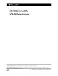
GAME SERIAL NUMBER LOCATION
Your game's serial number is located on the outside rear of the game . The
same number is also stamped on the chassis of the TV monitor, Game PCB
and Regulator/Audio PCB. Please mention this number whenever calling your
distributor for service.
GAME SERIAL#
IDENTIFICATION TAG
\
TV MONITOR
\
\
\
'
)
REGULATOR/AUDIO PCB
- - - : - - - - - GAME PCB
Operation, Maintenance
and Service Manual
Complete with Illustrated Parts Lists
Published by:
ATARI INC
1265 Borregas Avenue
P. 0. Box 427
Sunnyvale, California 94086
Copyright © 1979 by Atari, Inc.
All rights reserved
No part of this publication may be reproduced by any mechanical,
photographic, or electronic process, or in the form of a phonographic recording, nor may it be stored in a retrieval system, transmitted, or otherwise copied for public or private use, without permission from the publisher.
Lithographed in the U.S.A.
SJ
JI~
ATARI®
A Warner Commun1cat1ons Company
a
Asteroids
Table of Contents
1
Location Setup
A.
B.
C.
D.
E.
2
D.
E.
F.
G.
II
1
3
3
3
3
5
5
8
8
8
8
9
Maintenance and Repair
A.
B.
C.
3
New Parts . . . . . . . . . . . . . . . . . . . . . . . . . . . . . . . . . . . . . . . . . . . . . . . . . .
Game Inspection . . . . . . . . . . . . . . . . . . . . . . . . . . . . . . . . . . . . . . . . . . . .
Game Installation... . . . . . . . . . . . . . . . . . . . . . . . . . . . . . . . . . . . . . . . . .
1. Voltage Selection . . . . . . . . . . . . . . . . . . . . . . . . . . . . . . . . . . . . . . . .
2. Interlock and Power On/Off Switches . . . . . . . . . . . . . . . . . . . . . . . .
3. Game Fuses . . . . . . . . . . . . . . . . . . . . . . . . . . . . . . . . . . . . . . . . . . . .
Self-Test Procedure . . . . . . . . . . . . . . . . . . . . . . . . . . . . . . . . . . . . . . . . . .
Game Play . . . . . . . . . . . . . . . . . . . . . . . . . . . . . . . . . . . . . . . . . . . . . . . . .
1. Attract Mode . . . . . . . . . . . . . . . . . . . . . . . . . . . . . . . . . . . . . . . . . . . .
2. Ready-to-Play Mode . . . . . . . . . . . . . . . . . . . . . . . . . . . . . . . . . . . . . .
3. Play Mode . . . . . . . . . . . . . . . . . . . . . . . . . . . . . . . . . . . . . . . . . . . . . .
4. High Score Initial Mode . . . . . . . . . . . . . . . . . . . . . . . . . . . . . . . . . . .
Cleaning . . . . . . . . . . . . . . . . . . . . . . . . . . . . . . . . . . . . . . . . . . . . . . . . . .
Fuse Replacement . . . . . . . . . . . . . . . . . . . . . . . . . . . . . . . . . . . . . . . . . . .
Opening the Control Panel ........ .... .. .......... . ...........
1. Leaf Switch Replacement . . . . . . . . . . . . . . . . . . . . . . . . . . . . . . . . . .
2. LED Switch Replacement . . . . . . . . . . . . . . . . . . . . . . . . . . . . . . . . . .
TV Monitor Replacement ........ .......... ....... .......... ...
Printed Circuit Board Replacement .. ............ . ..............
Fluorescent Tube Replacement ........... ................ . . . ..
Game Operation .................... ........ . ........ ... .....
Illustrated Parts Lists
12
12
12
12
12
14
15
16
16
Asteroids
If reading through this manual does not lead to solving a certain
maintenance problem, call Tele-Help 1 M at the Atari Customer Service office
in your geographical area, as shown in one of the two maps below. Order
all parts from the California office.
WEST and CENTRAL U.S.A.
Parts for all Atari Customers. Sales and Service.
Atari Coin-Op Customer Service
1344 Bordeaux Drive, Sunnyvale, CA 94086
Telex 17-1103
(Monday - Friday, 7:30 - 4:00 pm Pacific Time)
From California, Alaska or Hawaii
(408) 745-2900
From anywhere else in this area
tol 1-free (800) 538-1611
EAST U.S.A.
Sales and Service Only
Atari Irie.
New Jersey Customer Service Office
Cottontail Lane, Somerset, NJ 08873
Telex 37-9347
(Monday - Friday, 8:30 - 5:00 pm Eastern time)
From New Jersey
(201) 469-5993
From anywhere else in this area
toll-free (800) 526-3849
iv
Asteroids
List of Illustrations
Figure 1
Figure 2
Figure 3
Figure 4
Figure 5
Figure 6
Figure 7
Figure 8
Figure 9
Figure 10
Figure 11
Figure 12
Figure 13
Overview of Game . . . . . . . . . . . . . . . . . . . . . . . . . . . . . . . . . . . . . . . . .
Installation Requirements . . . . . . . . . . . . . . . . . . . . . . . . . . . . . . . . . . .
Power Supply . . . . . . . . . . . . . . . . . . . . . . . . . . . . . . . . . . . . . . . . . . . . .
Interlock and Power On/Off Switches . . . . . . . . . . . . . . . . . . . . . . . . . .
Location of Self-Test Switch, Volume Control and Option Switches .
Self-Test Procedure . . . . . . . . . . . . . . . . . . . . . . . . . . . . . . . . . . . . . . . .
Option Switch Settings . . . . . . . . . . . . . . . . . . . . . . . . . . . . . . . . . . . . .
Opening the Control Panel ..................... .............
TV Monitor Removal .............. ... ... . .. .. . ............ . .
Game and Regulator/Audio PCB Replacement ..................
Fluorescent Tube Replacement ........ .... .. ................
Power Distribution ................... ........ .. .. ....... ...
Signal Distribution .........................................
2
3
4
4
5
6
7
13
14
15
16
17
18
Illustrated Parts Lists:
Figure
Figure
Figure
Figure
Figure
Figure
Figure
Figure
Figure
Figure
14 Flnal Assembly ......... ............. .... ...... . .... .. .....
15 Control Panel Assembly . . . . . . . . . . . . . . . . . . . . . . . . . . . . . . . . . . . .
16 Asteroids Game PCB Assembly ................. .. ...... .....
17 Regulator/Audio PCB Assembly .... ......... ....... ..........
18 Power Supply Assembly for X-Y Games .... .. ..................
19 Main Harness and Component Assembly ..... ........ . ..... . ...
20 Fluorescent Light Assembly ............ .......... ....... ....
21 Coin Door Assembly .......... ... .. .... . . ..... ........... ..
22 Front Bezel Assembly ...... .. ..............................
23 New Coln Door ............................................
20
22
24
28
30
32
33
34
36
38
Ill
Asteroids
Location Setup
A. New Parts
The Asteroids game has three new parts. If you
have worked on Atari games in the past, then you
should be aware of these important differences. The
new parts are:
• Power Supply Assembly. It covers a wider
voltage range than before, has higher reliability,
a smaller overall size, and all fuse numbers and
fuse amperages are marked directly on the metal
chassis.
• Game PCB Circuitry and TV Monitor. Most video
games to date have used the raster scan method
of display. This game uses vector generation
with X and Y axes to allow greater contrast, a
greater number of moving objects on the screen,
and lines at any angle to be "drawn" on the
screen.
Throughout this manual, wherever one of these
three new parts is mentioned, you will see this symbol in the page margin:.
Asteroids
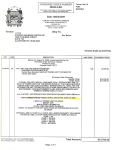
ATTRACTION PANEL
CONTROL
PANEL
REGULATOR/
AUDIO PCB
COIN DOOR
POWER SUPPLY
POWER ON/OFF SWITCH
Figure 1
2
Overview of Game
Asteroids
B. Game Inspection
C. Game Installation
This new game is ready to play upon removal from
the shipping carton. However, your careful inspection is needed to supply the final touch of quality
control. Please follow these steps to help us insure
that your new game was delivered to you in good
condition.
Figure 2
--~~~~NOTE~~~~--.
Do not plug the game in yet!
1.
2.
Examine the exterior of the game cabinet for
dents, chips, or broken parts.
Unlock and open the access panel of the
cabinet and inspect the interior of the game as
follows:
a. Check that all plug-in connectors (on the
game harness) are firmly seated. Replug
any connectors found unplugged. DON'T
FORCE CONNECTORS TOGETHER. The
connectors are keyed so they only go on in
the proper orientation. A reversed edge
connector will damage a PCB.
b. Check that all plug-in integrated circuits
on the game PCB are firmly seated in their
sockets.
.----- A
WARNING-----.
To avoid possible unpleasant electrical
shock, do not touch internal parts of the
TV monitor with your hands or metal objects held in your hands!
c.
Note the location of the game's serial
number-it is on the metallic label on the
back of the game cabinet. Verify that the
serial numbers also stamped on the Game
PCB, Regulator/Audio PCB and TV Monitor
are all identical. A drawing of the serial
number locations is on the inside front
cover of this manual. Please mention this
number whenever you call your distributor
for service.
d. Check all major subassemblies such as the
power supply, control panel and TV monitor
for secure mounting.
Installation Requirements
Power
Temperature
Humidity
Space Required
Game Height
1.
175 watts
Oto 38° C (32 to 100°F)
Not over 95% relative
65 x 79 cm (25V2 x 31 in.)
184 cm (72V2 in.)
Voltage Selection
Before plugging in your game, make sure that the
voltage selection plug on the power supply (see
Figure 3) is correct for your location's line voltage.
Check the wire color on the plug and see if it is correct per the list below.
Line Voltage Range
Voltage Selection Plug Color
90-110 VAC (100)
105-135 VAC (120)
200-240 VAC (220)
220-260 VAC (240)
Violet
Yellow
Blue
Brown
2.
Interlock and Power On/Off
Switches
To minimize the hazard of electrical shock while
working on the inside of the game cabinet, two interlock switches have been installed (see Figure 4).
One is located behind the access panel and one is
behind the coin door. These switches remove all AC
line power from the game circuitry when a door is
opened.
Check for proper operation of the interlock
switches by performing the following steps:
1.
2.
3.
Unlock and open the access panel and the coin
door.
Plug the AC line power cord into an AC outlet.
Close the access panel and coin door.
3
Asteroids
F6
0
VOLTAGE SELECTION PLUG
0
0
Figure 3
Power Supply
SWITCH
COVER
SWITCH
COVER
Figure 4
4
Interlock and Power On/Off Switches
Asteroids
4.
Set the power on/off switch to the on position.
Within 30 seconds the TV monitor should
display a picture.
5.
Slowly open the rear access panel. The TV
monitor picture should disappear when the
panel is opened approximately 2.Scm (1 inch).
Close and lock the access panel and repeat this
step with the coin door.
6.
If the results of step 5 are satisfactory, the interlock switches are operating properly. If the TV
monitor doesn't go off as described, check to
see if the corresponding interlock switch is
broken from its mounting or stuck in the on
position.
3.
Game Fuses
For continued protection of your game, as well as
for the safety of the players, fuses must be replaced
only with fuses with identical ratings. These ratings
are shown in Figure 18. See the Schematic Drawing
Package for fuse functions.
Information on the TV monitor fuses is contained
in the TV monitor manual that is supplied with this
game.
D. Self-Test Procedure
This game will test itself and provide data to
demonstrate that the game's circuitry and controls
are operating properly. The data is provided on the
TV monitor and the game speaker; no additional
equipment is necessary.
Part of the self-test procedure includes a display
of the operator-selectable game options. Therefore,
we suggest you run the self-test procedure anytime
you need to change the game's options.
To run the self-test, follow the instructions outlined in Figure 6.
VOLUME CONTROL
OPTION
SWITCHES
Figure 5
Location of Self-Test Switch, Volume Control and Option Switch
5
Asteroids
Figure 6
INSTRUCTION
1. Set self-test
switch to on position (see Figure 5).
RESULTS IF TEST
PASSES
TV monitor displays
picture as shown in
Figure 7.
Self-Test Procedure
RESULTS IF TEST FAILS
RAM FAILURE is indicated by a sequence of from 1to6 tones. A low-frequency
tone is heard for each good RAM chip. A much lower frequency is heard for a
failing RAM chip. The sequence stops with the last failing RAM chip. To restart
the sequence, press the Reset pushbutton on the game PCB or set the self-test
switch to off, then again to the on position. Identify the bad RAM chip with table
below. Example: Three tones, then a tone of much lower frequency indicates
failure of RAM chip R4.
RAM CHIP LOCATION
TONE#
D2
E2
M4
3
R4
4
N4
5
P4
6
ROM/PROM FAILURE is indicated by two columns or lines of numbers in the
upper left-hand corner of the display. The number in the left column or first line
indicates the failing ROM/PROM chip(s). Identify the bad ROM/PROM with table
below.
The number in the right column or second line indicates the failing data bit of
the failing ROM/PROM. Identify the bad bit with the second table below. If more
than one bit is failing, the displayed number(s) are hexadecimal combinations
of the numbers shown below. Examples:
1) If bits D2 and D3 fail, C is displayed.
2) If bits D2, D3 and D7 fail, BC is displayed.
3) If bits D4 and D5 fail, 30 is displayed.
4) If bits D1, D3, D5 and D6 fail, 6A is displayed
1
2
OISPLA YEO NO.
FAILING ROM/PROM
0
1
N/P3
K4, L4
2
3
F1
F2, L1
F2, H1
L2, L1
4
5
D/E1
H2, J1
H2, J1
M2, M1
6
7
C1
K1, J2
J2, K1
N2, N1
OISPLAYEO NO.
FAILING BIT
1
2
4
8
10
20
40
DO
D1
D2
D3
D4
D5
D6
D7
80
RAMSEL SIGNAL FAILURE is indicated by a BANK ERROR or PAGE SELECT
ERROR message at lower middle of display.
2. Activate all
control panel and
coin door switches.
When satisfied with
test, set self-test
switch to off position.
6
1 PLAYER START
and 2 PLAYER
START LEDs are
lighted. Highpitched click for
each activated
switch.
1 PLAYER START and/or 2 PLAYER START LEDs not lighted.
High-pitched click sound is not heard for any particular switch.
Asteroids
Figure 7
Option Switch Settings
When changing the options, verify proper results on the
TV monitor display during self-test. A switch toggle in the
on position is indicated by a O for that switch on the TV
monitor display. A switch in the off position is indicated by
the number 1.
To change toggle positions of the switch assembly, you
need not remove the game PCB. The switch, usually colored blue, is easily accessible when the game PCB is
mounted in place.
Toggle Settings of B·Toggle Switch
on Game PCB
8
7
6
5
4
3
Option
2
On
On
Off
011
On
Off
On
Off
On
On
Off
Off
On
On
Off
Off
On
Off
On
Off
English
German
French
Spanish
SWITCH
TOGGLE 1
CTR. COIN MECH
MULTIPLIER (LEFT
MECH OF A 2·MECH DOOR)
RIGHT COIN MECH
MULTIPLIER
SWITCH
TOGGLE 8
4-Shlp Game
3-Ship Game
Center Coin Mech x 1
Center Coin Mech x 2
(Both settings are for left
mech, ii a 2·mech door)
On
Off
On
Off
Right
Right
Rig ht
Right
On
Off
On
Off
Coln
Coln
Coln
Coln
Mech
Mech
Mech
Mech
x
x
x
x
1
4
5
6
Free Play
1 Coin' for 2 Plays
1 Coin· for 1 Play
2 Coins· for 1 Play
Photogreph above shows toggles 1, 2,
4-7 on, end toggles 3 and 8 oll.
Suggested settings are shown in illustration at right.
*Note: In the U.S. and Germany only, a "coin" is defined as 25¢ or 1 DM. If your game
also has $1 , 2 DM or 5 DM mechanisms, you must set the center and right coin
mechanism factors as per your choice.
Toggle Settings of 4-Toggle
Switch on Game PCB
4
3
2
1
For Games Having These Coin Doors:
On
On
Thai 1 Baht/1 Baht, German 1 DM/1 DM, U.S. 25¢/25¢,
Belgian or French 5 Fr/5 Fr, Swiss or French 1 Fr/1 Fr,
U.S. 25¢/25¢/25¢, Japanese Y100/Y100, Swedish 1 Kr/1
Kr, U.K. 10 P/10 P, Australian 20¢/20¢, or Italian 100
U100 L
All 3 coin mechanisms are
same denomination; all
register on one coin
counter.
Off
On
German 2 DM/1 DM, German 1 DM/5 DM, U.S.
25¢/25¢/$1, or U.S. 25¢/$1
Left and center mechanisms
are same denomination;
right mech is another
denomination. Requires two
coin counters.
On
Off
No coin door is currently designed for this configuration.
Left mech is one denomination; center and right mech
are another denomination.
Requires two coin counters.
Off
Off
German 1 DM/2 DM/5 DM
Left, center and right mechs
are 3 different denominations. Requires three coin
counters.
Option
7
Asteroids
E. Game Play
the center of the display. Four large asteroids appear and drift in from the outer edges of the display.
Atari's Asteroids game has five possible modes
of operation: Attract, Ready-to-Play, Play, High
Score Initial, and Self-Test. Self-test is a special
mode for checking the game switches and computer functions. You may enter this mode at any
time. When entered, all game credits are cancelled.
If the 2 PLAYER START pushbutton is pressed,
the following picture is displayed: the PLAYER 1
and PLAYER 2 scores become 00, and the number
of ships for the game appears below each score.
The player 1 score also flashes as the message
PLAYER 1 appears below the high score to date.
Two seconds after the 2 PLAYER START pushbutton is pressed, the PLAYER 1 message disappears.
The game ship for player 1 appears at the center of
the display as four large asteroids appear and drift in
from the outer edges of the display.
1.
Attract Mode
The attract mode begins when power is applied to
the game, after a play or high score initial mode, or
after self-test. This mode is continuous and is only
interrupted when a coin is inserted and accepted or
when in self-test. In this mode, the TV monitor
displays two possible pictures. Both pictures have
three score values across the top of the screen and
a message that states the number of coins for a
game. The middle score represents the high score
to date. The left score is for player 1. The right score
is for player 2.
One picture displays asteroids and an occasional
enemy spaceship "floating" across the screen. The
second picture displays up to 10 of the highest
scores since the game was last powered up or since
the last self-test. These two displays alternate every
16 seconds.
2.
Ready-to-Play Mode
This mode begins when sufficient coins have
been accepted for a one- or two-player game. It ends
when the 1 PLAYER START or 2 PLAYER START
pushbutton is pressed. When this mode begins, the
message PUSH START flashes immediately below
the center score at the top of the screen. The
displayed pictures are otherwise the same as those
shown in the attract mode.
3.
Play Mode
The play mode begins when either start pushbutton Is pressed. The mode ends when the player's
last ship of the game is lost.
If the 1 PLAYER START pushbutton is pressed,
the following picture is displayed: the PLAYER 2's
score disappears; the PLAYER 1's score becomes
00, and the number of ships (3 or 4, depending on
the operator's setting) for the game appears below
that score. The message PLAYER 1 also appears
below the high score to date. Two seconds after
pressing the 1 PLAYER START button the PLAYER 1
message disappears, and the game ship appears at
8
By pressing the LEFT ROTATE and RIGHT
ROTATE pushbuttons on the control panel, the
player may aim a spaceship toward any of the
asteroids. By pressing the FIRE pushbutton, the
player may shoot at the asteroids.
When shot, each large asteroid divides into two
medium-sized asteroids and the game adds twenty
points to the player's score. Medium-sized
asteroids, when shot, divide into two .small-sized
asteroids, and the player receives fifty points. Smallsized asteroids, when shot, will completely disappear, and the game awards 100 points to the player.
When players have shot all asteroids, a new set of
large asteroids again appear and drift in from the
outer edges of the TV monitor display. At the beginning of the game, four large asteroids appear. At the
beginning of the next cycle when large asteroids
reappear, there are six, the next time eight, and
thereafter ten-to increase player challenge.
At any time during game play, a flying saucer may
appear from either side of the display. The game
awards players 200 points for shooting a large
saucer and 1000 points for a small saucer. (The latter
is a smaller target for players, though not any faster
moving than the large one. It also shoots more accurately.)
The player's objective In the game is to shoot and
destroy as many asteroids as possible before all his
or her spaceships are destroyed. A ship is destroyed
if an asteroid or saucer smashes into it, or if a flying
saucer shoots it. To prevent losing a ship, the player
may press the THRUST pushbutton to move out of
the path of an asteroid or saucer. As an emergency
maneuver, players can press the HYPERSPACE
pushbutton: the ship disappears and reappears at a
random location on the display-however, possibly
right on top of, or in the path of, an asteroid. The
ship may also explode on reentry.
Asteroids
The game awards an extra ship each time a
player's score reaches multiples of 10,000; i.e., one
ship is awarded at 10,000 points, another ship at
20,000 points, etc.
When the last ship of the game is destroyed, the
message GAME OVER appears below the high
score. This message remains for 3 seconds before
the high score initial mode begins.
4.
High Score Initial Mode
At the beginning of the high score initial mode,
the player instructions appear at the top of the
screen, and A __ appears at the lower center of
the display. Players enter initials one character at a
time. By pressing the LEFT ROTATE pushbutton,
the displayed character steps through the alphabet
from A to Z. By pressing the RIGHT ROTATE
pushbutton, the character steps backwards through
the alphabet from A to a blank, then from Z to A.
Once the game displays the desired letter, players
should press the HYPERSPACE pushbutton to
record the letter; then an A appears in the next
space.
If players need only two letters for their initials,
they should use the blank between Zand A in one of
the three locations. Pressing the HYPERSPACE
pushbutton a third time will cause the initials and
game score to be transferred to the "10 highest
scores" listing that appears during the attract mode.
~.
9
..
··~ .
Asteroids
·Y>'""•
"\:J;
.,,..
.:, "Ji.
.
6·'·
...
,~
•
(J
.....
II
()
~
0
0
.
. (})
....
•. ·~.
Q
0
The Atari Asteroids game requires certain
maintenance to keep it in good working order.
Clean, properly maintained games attract players
and earn more profits.
The most important maintenance item is running
the self-test every time you collect money from the
cash box. Just looking at a game will not tell you If
LED switches or leaf switches are broken or if LEDs
have burned out. The self-test will inform you of any
of these possible problems.
Second, you should regularly clean the outside of
the game and the coin mechanisms. In addition, you
will need to regularly clean the leaf switch contacts:
for details see this chapter.
Maintenance
and Repair
Asteroids
A. Cleaning
The exterior of the game cabinet and the metal
and acrylic surfaces may be cleaned with any nonabrasive household cleaner. If desired, special coin
machine cleaners that leave no residue can be obtained from your distributor. Do not dry-wipe any of
the acrylic panels, because any dust can scratch the
~surface and result in fogging the plastic.
B. Fuse Replacement
This game contains six fuses-all on the power
supply assembly (not including the TV monitor
fuses). Replace fuses only with the same type as
listed in Figure 18 of this manual. See the
Quadrascan™ TV monitor manual, TM-151, for the
monitor fuse data.
C. Opening the Control
Panel
Prior to repairing or replacing any switch on the
control panel or prior to removing the TV monitor,
unplug the game. Then open the coin door.
Reach through the opening and remove both sets
of wing nuts, split lock washers, and flat washers,
located on the underside of the control panel (see
Figure 8). The two carriage bolts will remain in the
control panel.
Lift up on the control panel and tilt it towards you.
Be sure that the acrylic TV monitor shield does not
fall on you. The top edge of the control panel acts as
a retainer strip for tMe shield: once the control panel
is opened, the shield is free and could slide out
under its own power.
12
1.
Leaf Switch Replacement
All five of these leaf switches operate on 5 volts at
a very low current. Therefore, pitting of these
switches would be extremely rare. Probably the only
reason that pitting would occur is in very highhumidity locations.
Don't burnish the switches. Burnishing them
removes their plating, thus increasing the corrosion
of the contacts. The best method of cleaning the
switch contacts is to wipe them with a non-abrasive
surface. A business card works very well.
To replace any switch, remove both of its screws
with a Phillips-head screwdriver-see Figure 8.
If the white button itself needs to be replaced,
turn the stamped nut with a wrench in a
counterclockwise direction, as seen from the inside
of the control panel. The white ring on the outside of
the control panel should not spin, due to its design.
2. LED Switch Replacement
The light-emitting diode (LED) switches on the
control panel have a very low failure rate. In case a
switch should ever be suspect, first test it per the
description that follows. To replace the switch, refer
to Figure 8.
1.
Remove the wires from the suspected switch.
2.
Set multimeter to ohms scale. Set ohms scale
to R x 1, then zero the meter.
Check contacts (push and release the switch
button) for closed and open continuity.
3.
4.
If the contacts do not operate sharply or always
remain closed or open, then replace the LED
switch as outlined in the figure.
Asteroids
COMMON - \
CONTACT
~\
LIGHT-EMITTING
DIODE (L.E.D.)
CONTACTS
,____ NORMALLY OPEN
(N.O.) CONTACT
NORMALLY
CLOSED
(N .C.) CONTACT
L.E.D SWITCH:
TO REMOVE TURN
COUNTERCLOCKWISE
To remove LED switch:
II
•
Remove all wires from the faulty switch.
•
Turn the switch counterclockwise while holding the
black cone-shaped nut on the outside of the control
panel.
•
Install a new switch using the reverse procedure.
•
Reconnect the harness wires.
1
Adjust leaf switches for a narrow gap. When a
switch button is depressed, the resulting wiping action of the contacts provides a self·
cleaning feature.
TURN NUT TO
REMOVE WHITE BUTION
Figure 8
Opening the Control Panel
13
Asteroids
D. TV Monitor
Replacement
.---- A
1.
2.
WARNING
3.
High voltages may exist in any television unit,
even with power disconnected. Use extreme
caution and do not touch electrical parts or the
TV yoke area with your hands or with metal objects in your hands!
If you drop the TV monitor and it breaks, it will
Implode! Shattered glass and the yoke can fly
6 feet or more from the implosion. Use care
when replacing any TV monitor.
4.
5.
If you should need to remove the Quadrascan X-Y TV
monitor, follow steps 1 thru 6 on this page. Refer
also to Figure 9 below.
6.
Open the control panel as described in Section
C, Opening the Control Panel. Be sure the game
Is unplugged from its wall outlet!
Remove the acrylic TV monitor shield by sliding
its lower edge out.
Working up from the bottom side corners,
carefully pry loose the two side flaps of the
colorful 2-piece cardboard bezel. (A 4-inch strip
of double-sided adhesive tape is centered
behind both side flaps, flush with each edge.)
Remove the bezel as a complete unit-do not
remove the smaller part first.
Open the rear access panel and unplug the TV
monitor harness connectors-both are on the
TV's printed circuit boards.
Remove the four sets of carriage bolts, flat and
split lock washers, and hex nuts that hold down
the metal TV chassis.
Carefully slide the TV monitor chassis out the
front of the game.
Disassemble
In the order
Indicated
Figure 9
14
TV Monitor Removal
Asteroids
E. Printed Cirruit Board
Replacement
4.
5.
You may wish to remove the game printed circuit
board (PCB) or the Regulator/Audio PCB for service
or inspection. To do this, refer to Figure 10 and proceed as follows:
1.
2.
3.
Open the rear access panel.
Locate the securing screws and fiber washers
that hold down the PCB in its slots, and remove
them. (The game PCB has two, the Regulator/
Audio PCB has one set of this fastening hardware.)
If you are removing the game board, first remove
the two machine screws or tie wraps that fasten
the edge connector to the game PCB. Then
unplug the edge connector on the game PCB. If
you are removing the Regulator/Audio PCB,
simply disconnect the three small harness connectors on this board.
Carefully slide either PCB straight out of its
slots. Be careful not to twist the board, as this
may loosen connections or components. Replace or repair as required.
Reinstall the PCB, making sure that the connectors are properly plugged in. Note that they are
keyed to fit on only one way, so if they don't slip
on easily, don't force them! A reversed connector will probably damage your game and will
void the warranty.
6.
Replace the securing screws and fiber washers
in the PCB. Reinstall the fasteners used to
secure the edge connectors to the PCB. Close
and lock the rear access panel.
7.
Check that the operation of the game is correct
and perform the self-test. This is especially important with any game when you replace a PCB.
Normally the only adjustments on the Asteroids
game are option switch changes (made on the
4-toggle and 8-toggle DIP switches). Unless you
are qualified technician, do not turn any of the
knobs near the game PCB's edge connector.
Also do not turn the small knobs on the
Regulator/Audio PCB.
REGULATOR/
AUDIO PCB
ASTEROIDS
GAME PCB
Figure 10
Game and Regulator/Audio PCB Replacement
15
Asteroids
grams. These diagrams include information that explains the functions of the circuits and defines inputs and outputs.
F. Fluorescent Tube
Replacement
.---A WARNING
If you drop a fluorescent tube and it
breaks, it will implode! Shattered glass
can fly 6 feet or more from the implosion.
Use care when replacing any fluorescent
tube.
To replace the white fluorescent tube behind the
graphics attraction panel, follow this procedure (see
Figure 11).
1.
2.
3.
4.
5.
Remove the three Allen-head screws at the top
of the game. They secure the metal retainer for
the silk-screened panel. Remove the retainer
completely.
Tilt the top of the attraction panel towards you,
then lift it up and out of the bottom retainer.
Remove the two Y-shaped connectors from
the ends of the fluorescent tube. Now carefully remove the tube from its clamps by pulling
it towards you.
Replace with a new tube. Do not snap the tube
in vigorously-you may break it, causing in
implosion!
Close up the game and lock it.
G. Game Operation
With this manual you received two large sheets
that contain the wiring and schematic diagrams for
the Asteroids game. Sheet 1, Side A, includes information that shows the arrangement of these dia-
Figure 11
16
Atari's Asteroids is a microprocessor-controlled
game. The microprocessor is contained on the
game PCB. The game PCB receives switch inputs
from the control panel and coin door. These inputs
are processed by the game PCB and output to the
TV monitor, Regulator/Audio PCB and control panel.
The TV monitor is an X-Y monitor. Therefore, the
monitor receives signals for the X, Y and Z axes.
Since the location of the beam in the monitor is
totally controlled by the X- and Y-axis outputs of the
game PCB, the game PCB does not contain a standard sync circuit. The X- and Y-axis inputs to the
monitor step in increments of 1024 steps for the X
(horizontal) axis and 768 steps for the Y (vertical) axis. The Z axis merely controls the intensity of the
beam.
The Regulator/Audio PCB performs two funtions:
1) regulates the +..10.3 voe from the power supply
to + 5 voe, and 2) amplifies the audio output from
the game PCB. The + 5 VDC from the Regulator/
Audio PCB provides most logic power to the game
PCB. The audio output from the Regulator/Audio
PCB directly drives the game speaker and is controlled by the volume control mounted inside the
coin door.
The Power Supply is the source of all voltages in
the game. These voltages are protected by five
fuses in the fuse block on the Power Supply
chassis. The primary winding of the Power Supply
transformer is protected by the cartridge-type fuse
in the power supply chassis.
Figure 12 illustrates the distribution of power in
this game. Figure 13 illustrates the distribution of
signals.
Fluorescent Tube Replacement
Asteroids
FLUORESCENT LAMP
REGULATOR/AUDIO PCB
COIN DOOR--7----9--1
Q
POWER SU PPL Y
AC POWER CORD
Figure 12
Power Distribution
17
Asteroids
GAME SPEAKER
TV MONITOR
CONTROL
PANEL
.....
:::.
0
""~
:::.
.....
::..
.....
:::. .....
0
0
)(
:::. .....
0 :::.
>- 0
"'
GAME PCB
Figure 13
18
Signal Distribution
Asteroids
Illustrated Parts Lists
The purpose of this chapter is to provide you with
the necessary information for ordering replacement
parts for your Atari Asteroids game. Please note
that, for simplicity, common hardware has been
deleted from most of these parts lists. This includes
screws, nuts, washers, bolts, etc.
When ordering parts from your distributor, give
the part number, part name, applicable figure
number of this manual, and serial number of your
game. This will help to avoid confusion and
mistakes in your order. We hope the results will be
less downtime and more profit from your game.
0
...
0
co
.
~
~-
...
()
0
.·o
~
. () IJ
o~
0
•
0
~
Asteroids
3!
F'LUORP::SCl!.N1
LIG~T'
=
--=--
7 Places, c
- =
Green Ground
__ _
Wire
r, -- --'
nus
NOT ICE· TO AL L PERSON:> ~ECEJV I N G
D A~ WING
CO NFIOE NTlfl. L R~~uotl u e t lo n lcirbldOen w llhQ u! tf)e
I
~f11~~~irt~~~~,'~r:~~~~~a;11 1~'cCJ~ t~1 ;o~:~-r ;~ur\~1.'=~~
1
1
oel ll1flr '~t!U)I no1 rwsse~ tnn tn ~ rl:'.!O f c:onl~ r !i n1 ~ r-;m s·f e: f fi
anx tr~ h l m 1 Qr lli;<fl l'd ie 11J ut.ei . r h~ -subj ee 1 m.;;ller o f 11"1'1
l'h~w•ng i.:.it any desigri 1~ r 1e1;hnical 1 ~ f otmm lon !.tlp;wrl
0
1
11 1 0 1 1
:~~~~~~· ~ ~a"p~ r~ r r~, ~ ~u'r"if!'1~~~Y '~~~~3~i:·~~ ~A~~~~ rn~~
CQ~~o r s! I M's wtit·
urn llcrnt1 r,i~ tH'1 rl'(] l, 1 In ren rodl.Ka lhl.r;. tJriiwl fl l1 l.s Qrilnle<J
pol:il1ud and lor mi'1nuJr.c tu1·u u t1 dc 1 Hti3'
~r1 :ri'~ ~~~j~~~1~~tr1r~i~~!6r~~~l~: ~&r~b~~ll~r~Quwmenl
_ ,
@
Figure 14 Final Assembly
A035050·xx
M
20
Asteroids
Figure 14 Final Assembly
Parts List
Item
2
3
4
5
6
7
8
9
10
11
13
14
15
16
17
18
19
20
23
24
27
28
29
31
32
33
34
56
57
61
65
66
67
Part No.
Description
A035053-01
A035056-01
A034986-01
OR
A034986-02
A034485-01
A034561-01
A035158-03
A034628-01
A034841-01
OR
A034863-01
A036287-01
A021700-01
A021700-02
A021700-03
030249-01
A021084-01
A021084-02
A021084-04
A021084-05
A009083-xx
OR
71 -102201
71-102204
71-102206
71-102207
71-102208
71-102209
71-102210
71-102211
71-102212
71-103202
71-103203
71-103205
A035724-01
034457-01
035051-01
035049-01
034515-01
034516-01
TM-143
001638-01
006870-01
007882-02
007103-01
78-24012
034536-02
A035319-01
48-001
92-047
75-07017
70-303
TM-151
DP-143-01
DP-143-02
Control Panel Assembly-see Figure 15
Access Panel Assembly
Asteroids Game PCB Assembly (PROM version)-see Figure 16
~
~
Asteroids Game PCB Assembly (ROM version)-see Figure 16
Regulator/Audio PCB Assembly- see Figure 17
~
Power Supply Assembly for X-Y Games-see Figu re 18 -WU
Mai n Harness and Component Assembly-see Figure 19
Light and Speaker Harness Assembly
Strain Relief Power Cord (domestic)
Strain Relief Power Cord (German)
Fluorescent Light Assembly-see Figure 20
Coin Box Assembly (for all the same coins)
Coin Box Assembly (for two different coin denominations-has one separator)
Coin Box Assembly (for three different coin denominations-has two separators)
Coin Box Separator
Voltage Selection Plug, 100V
Voltage Selection Plug, 120V
~
Voltage Selection Plug, 220V
Voltage Selection Plug, 240V
~
Coin Door Assembly-see Figure 21
New Coin Door (U.S. 25¢/25¢)-see Figure 23
New Coin Door (German 2DM/1 DM)
New Coin Door (German 1DM/5DM)
New Coin Door (Belgian 5Fr/5Fr)
New Coin Door (Swiss 1Fr/1 Fr)
New Coin Door (Japanese 100Y/100Y)
New Coin Door (U.K. 10P/10P)
New Coin Door (Australian 20¢/20¢)
New Coin Door (Italian 100U100L)
New Coin Door (U.S. 25¢/25¢/25¢)
New Coin Door (U.S. 25¢/25¢/$1)
New Coin Door (German 1DM/2DM/5DM)
Cardboard Bezel Assembly with Graphics
Speaker Grille
Acrylic Attraction Panel with Graphics
TV Monitor Shield with Graphics
Upper Retainer Strip
Lower Retainer Strip
Asteroids Technical Manual
Control-Panel Mounting Bracket
Coin Box Bracket
Interlock Switch Cover
On/Off Switch Cover
5" Beaded Nylon Tie Wrap
Foam Vibration Damper for Game PCB
Coin Door Adapter Harness (only for A009083-xx coin door)
8 11 High-Fidelity Speaker
"'1///////111!
19" X-Y Black-and-White TV Monitor - . ,
Fiber Washer
18" 15-Watt Cool White Fluorescent Lamp
Manual for 15" and 19" Quadrascan X-Y Monitor
Asteroids TM Schematic Drawings (Sheet 1)
Asteroids Schematic Drawings (Sheet 2)
21
Asteroids
3 z eedo
NOTICE TO ALL PERSONS RECEIVING THIS
DRAWING
CONFID ENTIAL: Reprod uction lorbldden wl lhoul
Iha. specific wrl lten permission o f Atari, Inc.,
Sunnyvale, CA. This drawing Is only aondlllonally
Issued, and neither rece ipt nor possession ther-eof
confers or tren~le r s any rig.h i In, or llaense 10 use,
lh'e sub]ecl malt er cl Iha draw1ng or any design or
technical Information shown thereon, nor anr.
right to reproduce this drawing or any part thereo .
Except for manufacture by vendors of Atari, Inc.,
and for manufacture under the corporation's written license, no right to reproduce this drawing Is
granted or the subject matter thereof unless by
written agreement with or written permission from
the corporation.
5TAIC.T I
Figure 15 Control Panel Assembly
A035053·01
E
Parts List
Part No.
Description
1
2
035047-01
160001-001
3
4
62-039
033127-01
Control Panel with Graphics
Leaf Switch and Button Holder
(Leaf Switch only is part no. 160004-001.)
Momentary-Contact SPDT Light-Emitting Diode Switch
Black Molded Switch Bushing
5
10
11
17
A036046-01
75-9910NO
A035159-01
75,07054
Pushbutton Assembly
5/8"-11 Steel Stamped Nut
Control Panel Harness Assembly
Flat Nylon Washer
Item
22
"
Asteroids
~;k,'.· ;_': ::l~f;:~ I.:~ ~ ~ :
:~:
;; ·,r-. .:; · ·!
~
..
Board is permanently marked -03 or -04 after
"A034986", located between rows 10 & 11 (-03 for
PROM, -04 for ROM version).
Figure 16
24
Asteroids™ Game PCB Assembly
A034986-03 and -04
G
j
v
Asteroids
Figure 16
Item
2
3
4
5
6
7
8
9
10
11
12
13
14
15
16
17
18
20
Part No.
Description
100000-270
100000-680
100000-121
100000-151
100000-331
100000-471
100000-681
100000-102
100000-271
100000-122
100000-222
100000-272
100000-332
100000-392
100000-472
100000-562
100000-682
100000-103
27 Ohm, ±5%, 1/4W Resistor (R72)
68 Ohm, ±5%, 1/4W Resistor (R71)
120 Ohm, ± 5%, 1/4 W Resistor (R105, 109)
150 Ohm, ±5%, 1/4W Resistor (R55)
330 Ohm, ±5%, 1/4W Resistor (R30, 31, 115)
470 Ohm, ±5%, 1/4W Resistor (R32, 87-99)
680 Ohm, ±5%, 1/4W Resistor (R57, 61)
1K Ohm, ±5%, 1/4W Resistor (R27, 29, 53, 73, 85, 86, 132, 134)
270 Ohm, ± 5%, 1/4 W Resistor (R112-113)
1.2K Ohm, ±5%, 1/4W Resistor (R35, 100)
2.2K Ohm, ± 5%, 1/4 W Resistor (R36, 75, 117, 123, 133, 141)
2.7K Ohm, ±5%, 1/4W Resistor (R66)
3.3K Ohm, ± 5%, 1/4 W Resistor (R56, 65, 74, 142)
3.9K Ohm, ± 5%, 1/4 W Resistor (R39, 64, 106-108)
4.7K Ohm, ±5%, 1/4W Resistor (R37, 82, 102, 137, 140, 144)
5.6K Ohm, ±5%, 1/4W Resistor (R40, 62, 67)
6.8K Ohm, ±5%, 1/4W Resistor (R49, 104, 128, 129)
10K Ohm, ±5%, 1/4W Resistor (R9-26, 28, 33, 38, 54, 58-60, 63, 69, 70, 79, 80,
103, 110, 111, 116, 122, 130, 131, 135, 136, 138, 139)
12K Ohm, ±5%, 1/4W Resistor (R43)
15K Ohm, ±5%, 1/4W Resistor (R68)
18K Ohm, ±5%, 1/4W Resistor (R51, 146)
22K Ohm, ±5%, 1/4W Resistor (R1-8, 34, 41, 45, 50)
33K Ohm, ±5%, 1/4W Resistor (R52)
47K Ohm, ± 5%, 1/4 W Resistor (R42, 44, 48, 76, 78, 83, 114)
56K Ohm, ± 5%, 1/4 W Resistor (R145)
100K Ohm, ±5%, 1/4W Resistor (R46, 81, 84, 143)
220K Ohm, ±5%, 1/4W Resistor (R47)
270K Ohm, ±5%, 1/4W Resistor (R101)
39K Ohm, ±5%, 1/4W Resistor (R77)
33
100000-123
100000-153
100000-183
100000-223
100000-333
100000-473
100000-563
100000-104
100000-224
100000-274
100000-393
34
35
19-007
19-315103
39
40
41
44
21-101104
21-101224
21-101473
24-250105
45
46
47
49
50
51
24-250107
24-250477
24-250226
27-250102
27-250103
29-088
53
54
28-101100
28-101680
28-101101
28-101221
28-101271
28-101391
29·006
29-046
65-1 N100
31-1 N914
21
22
23
24
25
26
27
28
29
30
55
56
57
58
61
63
65
66
Asteroids™ Game PCB Assembly
Parts List
(Reference Designations and Locations in Bold)
10K Ohm, 8-Pin Resistor Network. Use with the LS170 only, item 120. (RP1, 2)
10K Ohm Vertical PCB-Mounting Cermet Trimpot, Bournes Series
3352V-1-10K (R120, 126)
.1 uf, ± 10%, Radial-Lead Epoxy-Dipped 100V Mylar Capacitor (C64, 67-69)
.22 uf, ± 10%, Radial-Lead Epoxy-Dipped 100V Mylar Capacitor (C33)
.047 uf, ± 10%, Radial-Lead Epoxy-Dipped 100V Mylar Capacitor (C46)
1.0 uf Aluminum Electrolytic Fixed Axial-Lead 25V Capacitor (C25, 70, 90, 92,
93)
100 uf Aluminum Electrolytic Fixed Axial -Lead 25V Capacitor (C19)
470 uf Aluminum Electrolytic Fixed Axial-Le.ad 25V Capacitor (C86, 87)
22 ut Alumi num Electrolytic Fixed Axial-Lead 25V Capacitor (C117)
.001 uf Ceramic-Disc 25V Radial -Lead Capacitor (C56)
.01 uf Ceramic-Disc 25V Radial-Lead Capacitor (C27, 32, 36, 40, 55, 58)
.1 uf Ceramic-Disc 25V Radial-Lead Capacitor (C1-18, 20-23, 26, 28-31 , 34, 37,
41-44, 49, 51-54, 57, 60, 61, 63, 65, 66, 71·85, 91, 94·96, 99-100, 103-104,
107-108, 111-112, 114•116, 120-123)
10 pf Radial-Lead Epoxy-Dipped 100V Mica Capacitor (C97, 105)
68 pt Radial-Lead Epoxy-Dipped 100V Mica Capacitor (C102, 110)
100 pf Radial-Lead Epoxy-Dipped 100V Mica Capacitor (C89)
220 pf Radial-Lead Epoxy-Dipped 100V Mica Capacitor (C98, 106, 118-119)
270 pf Radial-Lead Epoxy-Dipped 100V Mica Capacitor (C59)
390 pf Radial-Lead Epoxy-Dipped 100V Mica Capacitor (C88)
1.0 uf, ± 10% , 35V Tantalum Capacitor (C24, 35, 47, 50, 62, 113)
10 uf, ± 10%, 20V Tantalum Capacitor (C38, 39, 45, 48)
General Purpose Germanium Diode (CR16)
75V 1N914 Switching Diode (CR1-4, 6-8, 15)
25
Asteroids
Figure 16
Item
Part No.
Description
67
68
71
72
73
74
75
78
79
80
81
82
83
84
85
86
87
88
89
91
92
93
94
95
97
31-1 N4001
31-1N756A
33-2N3906
34-2N3643
34-2N3904
34-2N6044
34-MPSA06S
37-74LSOO
37-74LS02
37-7404
37-74LS04
37-7406
37-74LS08
37-74LS10
37-74LS14
37-74LS20
37-74LS32
37-74LS42
37-74LS74
37-74LS83
37-74LS86
37-7497
37-74LS109
37-74LS139
37-74LS157
98
99
101
102
104
105
106
107
37-74LS161
37-74LS164
37-74LS174
37-74LS175
37-74LS191
37-74LS193
37-74LS244
37-74LS245
OR
37-83048
37-74LS251
37-74LS253
37-74LS259
37-74LS273
37-74LS367
37-74LS393
37-74LS374
OR
37-74LS273
37-74LS670
OR
37-74LS170
37-9316
37-LM324
37-555
37-566
37-40168
37-TL082CP
37-AD561J
137108-001
50V 1N4001 Silicon Rectifier Diode (CR9-12)
8.2V, ±5%, 1N756A Zener Diode (CR13, 14)
Type 2N3906 PNP Switching and Amplifying Transistor (01-5, 7, 10, 16-17)
Type 2N3643 NPN Silicon Transistor (Q6)
Type 2N3904 NPN 60V 1-Watt Transistor (QB, 9)
Type 2N6044 Darlington NPN Transistor (011-13)
Type MPSA06S NPN 80V 500ma Transistor (014, 15)
Type 74LSOO Integrated Circuit (N5, C6)
Type 74LS02 Integrated Circuit (06)
Type 7404 Integrated Circuit (H10)
Type 74LS04 Integrated Circuit (B5, L5)
Type 7406 Integrated Circuit (N9)
Type 74LS08 Integrated Circuit (E6, K6, R7, BB)
Type 74LS10 Integrated Circuit (AB)
Type 74LS14 Integrated Circuit (B6)
Type 74LS20 Integrated Circuit (E5)
Type 74LS32 Integrated Circuit (M5, N6, B9)
Type 74LS42 Integrated Circuit (L6, E7, EB)
Type 74LS74 Integrated Circuit (04, A7, RB)
Type 74LS83 Integrated Circuit (M6)
Type 74LS86 Integrated Circuit (P5)
Type 7497 Integrated Circuit (F8, HS, JS, KB)
Type 74LS109 Integrated Circuit (A9)
Type 74LS139 Integrated Circuit (L3, E4)
Type 74LS157 Integrated Circuit (F3, H3, J3, K3, F6, A10, B/C10, F/H10, C10,
D/E10, E10)
Type 74LS161 Integrated Circuit (C5, PB, B7, C7, 07)
Type 74LS164 Integrated Circuit (K9, P9, R9)
Type 74LS174 Integrated Circuit (N7, P7, DB, N11, F10)
Type 74LS175 Integrated Circuit (M7)
Type 74LS191 Integrated Circuit (K5, C9, 09, E9, F9, H9, J9)
Type 74LS193 Integrated Circuit (F5, H5, J5)
Type 74LS244 Integrated Circuit (B2, C2)
Type 74LS245 Integrated Circuit (R2, E3)
108
110
111
112
113
114
116
117
118
119
120
121
122
124
125
127
128
129
130
26
Asteroids Game PCB Assembly, continued
Parts List
Type
Type
Type
Type
Type
Type
Type
Type
(Reference Designations and Locations in Bold)
83048 Integrated Circuit-substitute for item 107 (P2, E3)
74LS251 Integrated Circuit (J10, L10)
74LS253 Integrated Circuit (P6)
74LS259 Integrated Circuit (M10)
74LS273 Integrated Circuit (F7, H7, J7, K7)
74LS367 Integrated Circuit (H6, J6)
74LS393 Integrated Circuit (B4, 05)
74LS374 Integrated Circuit (B10, 010)
Type 74LS273 Integrated Circuit-substitute for item 117
Type 74LS670 Integrated Circuit (F4, H4, J4)
Type 74LS170 Integrated Circuit-substitute for item 119
Type 9316 Integrated Circuit
(C4)
Type LM324 Integrated Circuit (LB, P11)
Type 555 Timer Integrated Circuit (MB, NB, L9, R10)
Type 566 Function Generator Integrated Circuit (P10)
Type 40168 Integrated Circuit (M9, N10, R11, B12, 012)
Type TL082CP Integrated Circuit (A12, C12)
Type AD561J Integrated Circuit (B11, 011)
Operational Amplifier Integrated Circuit (B/C12, E12)
Asteroids
Figure 16
Asteroids™ Game PCB Assembly
Parts List
Description
Item
Part No.
132
133
134
135
137
139
141
142
143
144
146
148
150
151
152
155
157
37-7805
37-7812
37-7815
37-7915
38-MV5053
41-3003
62-001
66-118P1T
66-114P1T
79-42C40
81-4302
020670-01
90-102
90-6013
90-7033
034602-01
035127-01
159
159
035129-01
035130-01
(Reference Designations and Locations in Bold)
+ 5V Voltage Regulator (VR3)
+ 12V Voltage Regulator
+ 15V Voltage Regulator
(VR1)
(VR4)
-15V Voltage Regulator (VR2)
Type MV5053 Light-Emitting Diode (CR5)
100 uH, ± 5%, Hot-Molded Plastic Fixed R.F. Choke (L 1-L15)
SPST Pushbutton Switch (A6)
8-Station Single-Throw, Dual-lnline-Package Bit Switch (RS)
4-Station Single-Throw, Dual-lnline-Package Bit Switch (M12)
40-Contact Medium-Insertion-Force Integrated Circuit Socket (C3)
Nylon Snap-In Fastener
Test Point
12.096 MHz, ± .005%, Crystal (Y1)
Microprocessor (C3)
Random-Access Memory · (02, E2, M4, N4, P4, R4)
Programmable Read-Only Memory (CB)
Read-Only Memory (N/P3)
OR THE FOLLOWING TWO ITEMS:
Programmable Read-Only Memory, MSB-substitute for half of item 157 (K4)
Programmable Read-Only Memory, LSB-substitute for half of item 157 (L4)
For remaining memory components and their part numbers,
see listing below.
Memory Components and Their Equivalents
(Locations Shown in Bold)
-03 P.C. Boards
(PRO Ms)
035131-02
J2
035132-02
N2
035137-02
K1
035138-02
N1
035133-02
H2
035134-02
M2
035139-02
J1
035140-02
M1
035135-02
F2
035136-02
L2
035141-02
H1
035142-02
L1
Alternate -03 P.C. Boards
(PRO Ms)
035150-02
·04 P.C. Boards
(RO Ms)
J2
035143-02
035153-02
K1
035151 -02
H2
035144-02
035154-02
J1
035152-02
F2
035145-02
035155-02
C1
D/E1
F1
H1
27
I/)
-c
Q)
·e
iii
<(
1 ~ 1< .
'-
O\'>..,l
45'
t:...et;.
~\':::~
.ST-l'Jl.N\>...J
O\.=>=>o~,Tt..
"TRAC.£.::.
0
:$2J
c. F'L
~ '2.F'L
0
=nl
~_J
42)1' PL
·~ ei·
'::E.A..t<:.E..Q' t-.
xJ
(.=._.ii;
r'- •
;D
NOTICE TO ALL PERSONS RECEIVING THIS DRAWING
CON FIDENTIAL: Aep ro<luc·tion forbidden without th~
speeiflc written permission of A1art Inc., Sunnyvale, CA.
Th i s drawing Is only co n ditlonat l ~ Issued, an·<l nei ther
rec·eipt nor possession thereof confers or transfers any
rlgflt In, of'l1cense t.o use, the sub)ec't matter of t ~e drawi ng or any d"'s!gn or tec hnical Information show n theieQn,
nor any rig ht to reproduce thi s draw.Ing or any part
thereof. Except for man.ulaature by ven·dors of Atari, Inc.,
and for ma n u.!~ctu re under the corporat ion's written
license, no right to repr oduce this drawing Is gran te·d o·r
the subject matter t hereo f unless by written agreement
with or written permi ssion from the corporation.
~l ".>PL(Q~,5.l)
~
::c
CD
E
"'
~
m
0
~w
=a::::s,....
"i:: .;,
<(o
~!
CD<(
::::s (")
C>O
a:
......
,....
::::s
!
.2>
LL
tO
C\I
Asteroids
Figure 17
Item
Regulator/Audio PCB Assembly
Parts List
Part No.
Description
(Reference Designations in Bold)
2
3
4
5
110000-010
110000-100
110000-330
110000-101
1 Ohm, ± 5%, 1/4W Resistor (R10, 19)
10 Ohm, ± 5%, 1/4W Resistor (R11, 20)
33 Ohm, ± 5%, 1/4 W Resistor (R3)
100 Ohm, ± 5%, 1/4W Resistor (R4, 12, 17, 1S, 22)
6
7
8
9
110000-271
110000-102
110000-272
110000-752
270 Ohm, ± 5%, 1/4W Resistor (R1)
1K Ohm, ± 5%, 1/4W Resistor (R2)
2.7K Ohm, ± 5%, V4W Resistor (R23)
7.5K Ohm, ± 5%, 1/4W Resistor (R7)
10
11
13
15
110000-103
110000-392
110001-221
12-52P7
10K Ohm, ± 5%, 1/4W Resistor (R13, 14)
3.9K Ohm, ± 5%, 1/4W Resistor (RS)
220 Ohm, ± 5%, 1/2W Resistor (R9, 21)
2.7 Ohm, ± 5%, 1W Resistor (RS)
16
17
20
22
19-100P1015
19-315102
24-250106
24-250477
.1 Ohm, ± 3%, 7W Wirewound Resistor (R24)
1K Ohm Vertical PCB-Mounting Cermet Trimpot (RS)
10 ut Aluminum Electrolytic Fixed Axial-Lead 25V Capacitor (CS, 1S)
470 ut Aluminum Electrolytic Fixed Axial-Lead 25V Capacitor (C1, 4, 12)
23
25
26
27
24-250108
27-250103
27-250104
27-250224
100 uf Aluminum Electrolytic Fixed Axial-Lead 25V Capacitor
.01 uf Ceramic-Disc 25V Radial-Lead Capacitor (CS, C14)
.1 ut Ceramic-Disc 25V Radial-Lead Capacitor (C3, C11)
.22 ut Ceramic-Disc 25V Radial-Lead Capacitor (CS, 17)
29
31
32
34
27-250102
31-A14F
31-1 N4001
33-TIP32
.001 uf Ceramic-Disc 25V Radial-Lead Capacitor (C2, 7, 1S)
50V 2.5A Miniature Axial-Lead High-Current Rectifier (CR1, CR4)
50V Silicon Rectifier 1N4001 Diode (CR2-3)
PNP Power Transistor, Type TIP32 (02)
35
36
38
39
34-2N3055
34-2N3904
37-LM305
137151-002
NPN Silicon Transistor, Type 2N3055 03)
NPN Silicon Transistor, Type 2N3904 (04, S)
5V Linear Voltage Regulator (01)
Type TDA2002A 8W Linear Audio Amplifier Integrated Circuit
44
45
46
47
79-58008
79-58092
79-58059
79-20230
9-Position Connector Receptacle
6-Position Connector Receptacle
4-Position Connector Receptacle
Female PCB-Mounting Terminal
48
49
50
51
034531-01
72-1608C
75-99516
75-056
Heat Sink
#6-32 x 1/2" Cross-Recessed Pan-Head Corrosion-Resistant Steel Machine Screw
#6-32 Nut/Washer Assembly
#6 Internal-Tooth Steel Lock Washer
52
53
57
58
020670-01
75-F60805
78-16008
78-16014
Test Point
#6-32 x 1/2" Binder-Head Nylon Screw
Thermally Conductive Compound tor the 2N3055
Thermally Conductive Compound tor TDA2002A and TIP32
60
52-003
61
52-004
Teflon-Insulated Solder-Plated Solid Copper PCB-Mounting Jumper Wire with
.6" Centers
Teflon-Insulated Solder-Plated Solid Copper PCB-Mounting Jumper Wire with
.3" Centers
(C9, 10, 13)
(OS, 7)
(J7)
(JS)
(JS)
29
Asteroids
2 REQ'D
0
TOP VIEW
0
NOTICE TO ALL PERSONS RECEIVING THIS
DRAWING
CONFIDENTIAL: Re_producllo n forb id.den without
the specific wri l\en permlsslo1i o1 Alari, Inc.,
Sunnyvale, CA. This cir.a wing Is on ly conditionally
issued, and neither rnoelp nor possession thereof
confers or transfers any right in, or license to use,
the subject matter of the drawing or any design or
technical information shown thereon, nor any
right to reproduce this drawing or any part thereof.
Except for manufacture by vendors of Atari, Inc.,
and for manufacture under the corporation's writ·
ten license, no right to reproduce this drawing is
granted or the subject matter thereof unless by
written agreement with or written permission from
the corporation.
6 REO'D
0
0
BOTTOM VIEW
0
0
Figure 18
Power Supply Assembly for X·Y Games
A034561 ·02
30
E
Asteroids
Figure 18
Item
Power Supply Assembly for X·Y Games
Parts List
Part No.
Description
A
1
2
3
A034955-01
034482-01
79-4411006
79-3206
Power Supply Sub-Assembly, Rev. A, consisting of the following 17 items:
Base for Power Supply Chassis
Panel-Mounting Non-Indicating 3AG Cartridge-Type Fuse Post
5-Position 3AG Fuse Block with 1/4" Quick-Disconnect Terminals
4
5
6
7
46-2017002
46-2013002
29-053
78-70501SC
7-Amp. 250V 3AG Slow-Blow Glass Cartridge-Type Fuse
3-Amp. 250V 3AG Slow-Blow Glass Cartridge-Type Fuse
26,000 uf 15V Electrolytic Capacitor
2" Diameter Capacitor Mounting Bracket
8
9
79-15021001
78-2708
10
11
A006555-01
72-HA4804S
2-Circuit Single-Row Terminal Block
Nylon Type 6/6 Hole Bushing with 5/8" Inside Diameter x 55/64" Outside
Diameter x 1/4" Thick
Rectifier Printed Circuit Board Assembly
#8-32 x 1/4" Cross-Recessed Pan-Head Zinc-Plated Steel Thread-Rolling Tri-Fluted
"Taptite" Screw
12
72-HA4812S
13
72-1008F
14
72-HA4606S
15
75-010S
#8-32 x 1/4" Cross-Recessed Pan-Head Zinc-Plated Steel Thread-Rolling Tri-Fluted
"Taptite" Screw
#10-32 x V2" Cross-Recessed Pan-Head Zinc-Plated Steel Thread-Rolling TriFluted "Taptite" Screw
#6-32 x 3/8" Cross-Recessed Pan-Head Zinc-Plated Steel Thread-Rolling Tri-Fluted
"Taptite" Screw
#10 Flat Plain SAE-Standard Zinc-Plated Steel Washer
16
17
B
c
75-018S
75-99518
A034630-01
A034629-01
#8 Flat Plain SAE-Standard Zinc-Plated Steel Washer
#8-32 Nut/Washer Assembly
RFI Filter Assembly
A.C. Harness Assembly
D
E
F
G
A034623-02
034544-01
75-018S
75-99518
Power Supply Harness Assembly (for X-Y Games)
Fuse Block Cover
#8 Flat Plain SAE-Standard Zinc-Plated Steel Washer
#8~32 Nut/Washer Assembly
H
72-HA4812S
J
A035674-01
#8-32 x 314" Cross-Recessed Pan-Head Zinc-Plated Steel Thread-Rolling Tri-Fluted
"Taptite" Screw
Voltage Plug Assembly (set of four)
31
Asteroids
BK
2.
NOTICE TO ALL PERSONS RECEIVING THIS
DRAWING
CONFIDENTIAL: Reproduction forbidden without
th e specific written perml"Ssion or Atari, Inc.,
Sunnyvale, CA . T~ ls drawing Is only cond itional ly
issued, and neHher receipt nor possession I hereof
confers or transfers any rig ht In, or license t o use ,
the subject matter of the drawing or any design or
te chnical inlormalion show n lhereon, nor ~ n(.
right to reproduce th is drawi ng or any part thereo .
Except for manufacfu re by vendors ol Al arl, Inc.,
and for manufacture under tha corporation' s wrU·
ten license, no right lo repmd uce this drawing Is
granted or the subject mau er thereo f unless by
written agreement with or written permission from
the corporation .
BK
1)
5
w
---
,,~ -02. ONLY
w,
B K I1
---
/
I
I
/
BN & BN
Figure 19
Main Harness and Component Assembly
A035158·03
C
Parts List
Item
1
2
3
5
32
Part No.
Description
A035157-02
A034631-01
A036189-01
A030169-02
Main Harness Assembly
On/Off Switch Assembly
Interlock Switch (2 per game)
Volume Control/Bracket Assembly
Asteroids
NOTICE TO ALL PERSONS RECEIVING THIS DRAWING
CONFIDENTIAL: Reproduction forbidden without the
specllio wrlltep permission ol Atari, Inc., Sunnyv.ale, CA.
Thls drawing Is only nonditlonally Issued, and neither
receipt nor possession lhorool conlers or transfers any
rlghl In, or llcense 10 use, Iha subject matter ol Iha dra"I·
Ing or any de.sign or teohnlcal Information shown thereon,
nor any r1g·i ;1 lo reprnduce this drawing or any part
thereof. Except ror manuf.acture by vendorn of Atari, Inc.,
and lor manulacture under the corporation's written
license, no right to reproduce thls drawing Is granted or
the subject mailer l.Mreo f un less by written agreement
wllh or wrlllen permission from the corporation ,
"
It
NOTICE TO ALL PERSONS RECEIVING THIS
DRAWING
CONFIDENTIAL: Reproduction forbidden without
the speolflo written permission of Atari, Inc ..
Sunnyvale, CA. This drawing ls·onfy conditionally
Issued, and neither receipt nor possession thereof
confers or transfers any right In, or license to use,
lhe subjecl mailer of the drawing or any deslgn or
technical Information shown 1neroon, nor anr.
rig hi lo reproduce this drawing or any .part thereo ,
Excepl for manufacture by vendols of Atari, Inc.,
and for manufacture under tho corporation's ,writ·
tetl license, no rlghl to reproduce this drawing Is
.1Jranfed or \ha subject mailer thereof unless by
written agreement wlih or written permission from
th e corporal lon.
Figure 20
Fluorescent Lioht Assembly
A036287·01
A
Parts List
Item
1
2
3
4
5
6
7
Part No.
Description
A005493-01
79-561816P
99-11003
99-11008
99-11009
99-11011
035835-01
Fluorescent Light Harness
Spring Connector Wire Nut for 16- to 18-Guage Wires
Fluorescent Lamp Starter
Ballast Transformer
Starter Socket
1V2 11 Clamp
Y-Lead Connector (part no. A036045-01 is an acceptable substitute)
33
Asteroids
NOTICE TO ALL PERSONS RECEIVING THIS DRAWING
R&pfoduc:t1co ro rbidden wllhOul ttte
CONFIO~NTIAL-
~T11~:~iaw~i~tr:"d~:,'i~~!~~o.;n1~'co~~.r?io~~~Y 1 :sU:e°J.v!~ci
neither receli;it rior ~oue_ss1or:-1ne1eol conlers or 111ri1rer:i.
any righl Ill. Gr flcenss to use. 1na subject mauet ot ll"ce
drawing or any design o, 1ecMlc:al ln torf'llllfon fllown
thereon, oOr ant rlghl to reproduce tn fs dr11wfng or 11ny pari
~h0~~~~d =~~efc1, t;;.r,~~,~~~~;!u~~::, ~~~ag~~P~r.i~t1~~1 ~n~~~:
Ian license, no right to reproduce this drawing is granted
or the subject mailer !hereof unless by written agreement
with or written permission from the corporatior
Figure 21 Coin Door Assembly
A006794·16 thru ·28 K
34
Asteroids
Figure 21
Item
1
Part No.
A007637-16
A007637-17
A007637-18
A007637-19
A007637-20
A007637-21
A007637-22
A007637-23
A007637-24
A007637-25
A007637-26
A007637-27
A007637-28
2
72-HA4608C
3
4
5
6
8
9
10
11
12
13
15
16
17
18
20
A030362-01
A030250-01
A002465-01
004320-01
004344-01
004340-01
004337-01
004338-01
004336-01
004326-01
006904-01
030257-01
70-11-47
73-3008
72-HA4604C
21
75-99516
22
23
24
008629-01
71-2118
71-1225CU
71-1205FF
71-1201MG
71-1201KS
71-12100YJ
71-1210PE
71-1220CA
71-1202MG
71-1201FF
71-1201 BT
71-1205MG
71-12100LI
71-1201ADU
007753-01
A007638-01
75-036S
73-3025
25
26
27
28
30
32
33
34
75-056
033368-01
033369-01
033371-01
Qty.
Coin Door Assembly
Parts List
Description
Front Bezel Assy.-Used only on -16 Coin Door Assy. (25¢)
Front Bezel Assy.-Used only on -17 Coln Door Assy. (5 Fr)
Front Bezel Assy.-Used only on -18 Coln Door Assy. (1 DM)
0
"O ::J
Front Bezel Assy.-Used only on -19 Coin Door Assy. (1 Kr)
CD CD
..., 0
Front Bezel Assy.-Used only on -20 Coin Door Assy. (100 Y)
oFront Bezel Assy.- Used only on -21 Coin Door Assy. (10 pence)
0 ......
-·~
Front Bezel Assy.-Used only on -22 Coin Door Assy. (20¢
::J CD
a.(/)
Australian)
0 CD
Front Bezel Assy.-Used only on -23 Coin Door Assy. (2 DMl1 DM)
.., (/)
Front Bezel Assy.-Used only on -24 Coin Door Assy. (1 Fr)
Front Bezel Assy.-Used only on -25 Coin Door Assy. (1 Baht)
Front Bezel Assy.-Used only on -26 Coln Door Assy. (1 DM/5 DM)
Front Bezel Assy.-Used only on -27 Coin Door Assy. (100 Lire)
Front Bezel Assy.-Used only on -28 Coin Door Assy. (25¢/U.S. $1
coin)
For breakdown of Front Bezel Assy., see Figure 22
3
#6-32 x V2" Cross-Recessed Pan-Head Cadmium-Plated Steel TriFluted Thread-Rolling Screw
1
Coin Lockout Assembly
2
Coin Switch Assembly
1
Coin Counter Assembly
1
Coin Door Weldment
1
Key Loop
2
Spring Return (used only on German DM coin doors)
2
Bracket for Lock-Out Wires
1
Right-Hand Lock-Out Wire
1
Left-Hand Lock-Out Wire
2
Scavenger Button
2
Spacer (used only on German DM coin doors)
1
Lamp Socket
1
NEMA #47 Incandescent Miniature Bayonet-Base Lamp
2
Carbon Spring Steel External Retaining Ring, for 1/4" Diameter Shaft
2
#6-32 x 1f.I" Cross-Recessed Pan-Head Cadmium-Plated Steel TriFluted Thread-Rolling Screw
13*
#6-32 Steel Nut and Spring Washer Assembly
*Quantity of 15 is used on the German DM coin doors
2
Spring
1
Cam Lock, Hudson #CR73A045S
Coin Mechanism for American Quarter
Coin Mechanism for French 5-Francs Coin
Coin Mechanism for German 1-Mark Coin
"O Ill
Coin Mechanism for Swedish 1-Krona Coin
Ill CD ::J
(/) ..... '<
Coin Mechanism for Japanese 100-Yen Coln
..... 0 0
Coin Mechanism for English 10-Pence Coin
CD
0
.0
c: -·
::J ......
Coin Mechanism for Australian 20-Cent Coin
-·a.~
Coin Mechanism for German 2-Mark Coin
0. 0 CD
Coin Mechanism for French 1-Franc Coln
.....
Coin Mechanism for Thai 1-Baht Coin
Coin Mechanism for German 5-Mark Coin
Coin Mechanism for Italian 100-Lire Coin
Coin Mechanism for U.S. $1.00 Coin
1
Anti-Probe Plate
1
Slam Switch Assembly
4
#6 Flat Plain SAE-Standard Zinc-Plated Steel Washer
6
Carbon Spring Steel External Retaining Ring, for 0.184" Diameter
Shaft
1
#6 Internal-Tooth Zinc-Plated Steel Lock Washer
1
Lock Bracket
1
Lock Arm
1
Slam Switch Insulator
t
oc
r
t~
mom
li
35
Asteroids
NOTICE TO All PERSONS RECEIVING THIS DRAWING
CONFIDENTIAL Aeproduc11on forbidden wrlhoul the
spec1llc written permis5aon of A lau_ loi::: .. Sunnyvale.
Cal1lornla. This drawing 1~ only c nm;Hll1'inally issued, and
neither receipt nor posse ss io n 11Hirno l CQn far> or translers
any right 1n, or l1c~nse lo Ul56, the s Ubfe1;1 mailer ol lhe
drawing or any design or 1enh111 .u rnlotm:tt1on shown
thereon nor any right 10 reproduce this drawing or any parl
thereol, except lor manufacture by vendors ol Alar1. lncor·
porated and lor manufacture under the corporatmn's wnt·
ten license, no nghl to reproduce this drawing 1s granted
or lhe sub1ecl matter thereof unless by wnllen agreement
wrlh or wnllen permission lrom Lhe corporal1on
Figure 22
Front Bezel Assembly
A007637·16 thru ·28
Parts List
Item
Part No.
8
9
004328-02
004330-02
004330-02
009153-02
004330-02
009153-02
007752-02
007752-02
030677-02
009153-02
030677-02
007752-02
030677-02
004331-02
004332-02
004327-01
004329-01
004343-01
004343-06
004343-04
004343-03
004343-05
004343-02
004343-07
004343-08
004343-09
004343-10
004343-11
004343-12
004343-13
73-3009
72-1604S
10
11
75-046
72-CL606
13
75-056
1
2
3
4
5
6
7
7
36
Qty.
+_.
:E
"O
<1> 0
..., 0
.....
(')
o-·~
c. (/)
::i <1>
0 <1>
0..., (/)
c:
<1>
ic.
2
2
2
2
t
0
::i
"O <1>
~o
(')
.....
o-·~
c. (/)
::i <1>
0 <1>
0..., (/)
c:
{'
2
3
2
6
J
Description
Bezel
Ring for American Quarter
Ring for French 5-Franc Coin
Ring for German 1-Deutschmark Coin
Ring for Swedish 1-Krona Coin
Ring for Japanese 100-Yen Coin
Ring for English 10-Pence Coin
Ring for Australian 20 Coin
Ring for German 2-Deutschmark and U.S. $1.00 Coins
Ring for French 1-Franc Coin
Ring for Thai 1-Baht Coin
Ring for German 5-Deutschmark Coin
Ring for Italian 100-Lire Coin
Coin Shield
Primary Coin Chute
Scavenger Button Bearing
Price Plate Clamp
Price Plate-25¢
Price Plate-5 FR
Price Plate-1 OM
Price Plate-1 KR
Price Plate- '16 100
Price Plate-10 P
Price Plate-20¢ Australian
Price Plate-Einwurf 2 DM/1 OM
Price Plate-1 FR
Price Plate-1 Baht
Price Plate-Einwurf 1 DM/5 OM
Price Plate-100 Lire
Price Plate-25¢/$1
Carbon Spring Steel External Retaining Ring, for 3/8" Shaft Diameter
#6-32 x 1/4" Cross-Recessed Pan-Head Cadmium-Plated Steel
Machine Screw
#6 Corrosion-Resistant Steel Split Lock Washer
#6-32 x 3/8" Phillips Pan-Head Steel "Rolok" Self-Threading,
Thread-Rolling Machine Screw
#6 Internal-Tooth Zinc-Plated Steel Lock Washer
Asteroids
99-10103
75·948S
75·1408S~
~#
75·944S
99·1006:9·100\96
COIN INLET
CHUTE { 99-10101
. ··
/',
70·11·47
99-10080
72·9406S
~
~~
.'"'-?h-~o/
/~1~ ~ -
\ ...;'.?
/
"'
99-10104
COIN MECHANISM
SEE PARTS LIST
(71·12xxxx)
75-944S
99·10102
COIN RETURN
{
CHUTE
99·10065
99·1006/
COIN SWITCH ASSY.
SEE PARTS LIST
(99·10042 thru
99·10045)
65·441C
72·9603S
SWITCH WIRE
SEE PARTS LIST
(99·10075 thru
99·10078)
31·1N4002
PART OF 99·10047
99-10008
99·10082
75·1412S
Figure 23 New Coin Door
71·10xxxx
38
Asteroids
~
~
REJECT BUTION COVER
SEE PARTS LIST (99·10055 thru 99·10059)
PRICE PLATE
SEE PARTS LIST
(99-10070, 99-10083
thru 99·10092)
COIN RETURN BUTTON ASSY
SEE PARTS LIST
(99-10012 thru 99-10022)
99·10074
72·JA1405B
COIN DOOR ONLY
SEE PARTS LIST
(99·10009 thru 99-10010)
99·10054
72·HA1404C
99·10094
75·55208
NOTICE TO ALL PERSONS RECEIVING THIS DRAWING
CON~ !DEN~IAL: Reproduction lorbidden withoul the
spe_cr 1c. wnll.en per.mission or Atari, l(lc .. Sunn vale
Ca_l1forma. ~his drawmg is only conditionally issued
ne1th~r re~e1pl n~r possession thereof confers or tran~fers
any ~1ght m, or hcen_se lo use, the subject mailer of the
drawmg or any ~es1gn or technical information shown
thereon, nor any right lo reproduce this drawing or an
art
lhereol, except for manulacture by vendors ol Atari 1 rn~o
pora~ed and lor i:nanufacture under the corporalion 's wri~:
ten l1cens~. no r1ghl lo reproduce this drawing is granted
o~ the sub!ect matter thereol unless by wrilten agreement
with or written permission from lhe corporation
1
and
99·10066
75·915S
72·JA1405B
99·10051
Figure 23 New Coin Door
71·10xxxx
39
Asteroids
Figure 23
New Coin Door, continued
Parts List
Part No.
Description
31-1N4002
65-441C
70-11-47
71-1201ADU
71-1201FCH
100V Silicon Rectifier 1N4002 Diode
General-usage low-force miniature switch
Miniature bayonet-base incandescent lamp, type #47
U.S. $1.00 coin mechanism
Swiss 1 Fr coin mechanism
71-1201MG
71-1202MG
71-1205FB
71-1205MG
71-1210PE
German 1 OM coin mechanism
German 2 OM coin mechanism
Belgian 5 Fr coin mechanism
German 5 OM coin mechanism
U.K. 10 P coin mechanism
71-1220CA
71-1225CU
71-12100LI
71-12100YJ
72-HA1404C
Australian 20¢ coin mechanism
U.S. 25¢ coin mechanism
Italian 100 Lire coin mechanism
Japanese Y100 coin mechanism
#4x1/4" Slotted pan-head thread-rolling tri-fluted "Taptite" cadmium-plated screw
72-JA1405B
72-9406S
72-9603S
75-915S
75-918S
#4x5/16" Slotted pan-head thread-rolling tri-fluted "Plastite" black screw
#4-40x3/8" Slotted truss-head steel machine screw
#6-32x3/16" Slotted truss-head steel machine screw
#1/4-20 Standard pattern cadmium-plated steel hex nut
#8-32 Standard pattern cadmium-plated steel hex nut
75-944S
75-948S
75-1408S
75-1412S
75-5520B
#4-40 Polymer self-locking steel hex nut
#8-32 Polymer self-locking steel hex nut
#4-40x1/2" Slotted pan-head steel machine screw
#4-40x3/4" Slotted pan-head steel machine screw
#1/4-20x11/4" Round-head square-neck steel bolt with black finish
99-10008
99-10009
99-10010
99-10011
99-10012
Switch wire retainer
2-Mech coin door only
3-Mech coin door only
Inner panel
U.S. 25¢ coin return button assembly
99-10013
99-10014
99-10015
99-10016
99-10017
U.S. $1.00 coin return button assembly
German 1 OM coin return button assembly
German 2 OM coin return button assembly
German 5 OM coin return button assembly
Belgian 5 Fr coin return button assembly
99-10018
99-10019
99-10020
99-10021
99-10022
Swiss 1 Fr coin return button assembly
Japanese Y100 coin return button assembly
U.K. 10 P coin return button assembly
Australian 20¢ coin return button assembly
Italian 100 Lire coin return button assembly
40
Asteroids
Figure 23
New Coin Door, continued
Parts List
Part No.
Description
99-10040
99-10041
99-10042
99-10043
99-10044
Coin
Coin
Coin
Coin
Coin
99-10045
99-10047
99-10048
99-10049
99-10051
Coin switch assembly for German 5 DM, U.K. 10 P, and Australian 20¢ coins
Lockout coil assembly
Coin door harness assembly
Locking arm assembly
Coin door frame
99-10054
99-10055
99-10056
99-10057
99-10058
Coin
Coin
Coin
Coin
Coin
99-10059
99-10061
99-10062
99-10063
Coin return button cover for German 5 DM, U.K. 10 P, and Australian 20¢ coins
Coin return bezel
Coin return button
Right half of coin inlet chute
99-10064
99-10065
99-10066
99-10070
99-10071
Left half of coin inlet chute
Coin return box
Coin return cover
U.S. 25¢ price plate
Slam switch assembly
99-10073
99-10074
99-10075
99-10076
99-10077
Test switch decal
Lock assembly
Black switch wire-for German 1DM, Swiss 1Fr and Japanese Y100 coins
Silver switch wire-for U.S. 25¢ and Belgian 5Fr coins
Gold switch wire-for U.S. $1.00, German 2DM and Italian 100 Lire coins
99-10078
99-10080
99-10081
99-10082
99-10083
Green switch wire-for German 5DM, U.K. 10P and Australian 20¢ coins
Miniature bayonet-base lamp socket
Wire key holder
Switch cover
U.S. $1.00 price plate
99-10084
99-10085
99-10086
99-10087
99-10088
German 1 DM price plate
German 2 DM price plate
German 5 DM price plate
Belgian 5 Fr price plate
Swiss 1 Fr price plate
inlet chute assembly
counter assembly
switch assembly for U.S. 25¢ and Belgian 5 Fr coins (silver wire)
switch assembly for German 1 DM, Swiss 1 Fr, and Japanese Y100 coins (black wire)
switch assembly for U.S. $1.00, German 2 DM, and Italian 100 Lire coins (gold wire)
button housing
return button cover
return button cover
return button cover
return button cover
for
for
for
for
(green wire)
Japanese Y100 coin
German 1 DM and Swiss 1 Fr coins
U.S. 25¢ and Belgian 5 Fr coins
U.S. $1.00, German 2 DM, and Italian 100 Lire coins
41
Asteroids
Figure 23
New Coin Door, continued
Parts List
Part No.
Description
99-10089
99-10090
99-10091
99-10092
99-10094
Japanese Y100 price plate
U.K. 10 P price plate
Australian 20¢ price plate
Italian 100 Lire price plate
Fish paper insulation
99-10095
99-10096
99-10097
99-10101
99-10102
Toggle switch
"U"-type fastener
Fish paper insulation
Coin lnlet chute sub-assembly
Switch and lockout coil bracket sub-assembly
99-10103
99-10104
99-10105
Inner panel with levers sub-assembly
Anti-penny-flip bar retainer
Anti-penny-flip bar
42
I
I
I
I
I
I
I
I
I
I
I
I
I
I
Asteroids
TM-143
5th printing
YOUR COMMENTS, PLEASE!
Your comments will assist Atari in improving the usefulness of our publications . They
are an important part of preparing for revisions of manuals and parts catalogs. No
postage stamp is necessary if mailed in the U.S.A.
If you have any technical questions about certain Atari or Kee Games products, or are
requesting additional publications, we will immediately forward your note to the appropriate person.
Comments:
Page:
I
I
I
I
~
I
I
I
I
I
I
I
I
I
I
I
I
I
I
I
Fill in if you wish a reply :
Name _ __ _ _ _ _ _ _
Firm
Address - -- - -- -- - -- - - - -- -- - City
_ _ _ _ _ State _ _ _ _ _
Zip _ _ __ _
0 Distributor
0 Operator
0 Other _ __ _
I
I
I
I
I
I
I
I
I
I
I
~~
- - - - - - - - - - - - - - - - - - - - - -- - - - - 1
I
No Postage
Necessary
1f mailed in
the United States
I
I
1
I
I
BUSINESS REPLY MAIL
FIRST CLASS
PERMIT NO. 1004
I
SUNNYVALE, CA
1.~
I~
POSTAGE WILL BE PAID BY ADDRESSEE
Atari, Inc.
Attn.: Field Service/Coin-Op Division
P. 0. Box 427
Sunnyvale, California 94086
- - - - - - -- - - - - - -
il
la
I
I
I
I
I
- -- - - - - - - - - - -1
Second fold
9801>6 \f:) '31\fMNNOS
LZt XOB "O"d
":)NI 'IH\fL\f
a6pa S!41 ade.t
WARRANTY
Seller warrants that its printed circuit boards and parts thereon are free from defects in material
and workmanship under normal use and service for a period of ninety (90) days from date of
shipment. Seller warrants that its television monitors (in games supplied with monitors) are free
from defects in material and workmanship under normal use and service for a period of thirty
(30) days from date of shipment. None of the Seller's other products or parts thereof are warranted.
If the products described in this manual fail to conform to this warranty, Sellers' sole liability shall
be, at its option, to repair, replace, or credit Buyer's account for such products which are returned to Seller during said warranty period, provided:
(a) Seller is promptly notified in writing upon discovery by Buyer that said products are
defective;
(b) Such products are returned prepaid to Sellers' plant; and
(c) Seller's examination of said products discloses to Seller's satisfaction that such
alleged defects existed and were not caused by accident, misuse, neglect, alteration, improper
repair, installation or improper testing.
t
In no event shall Seller be liable for loss of profits, loss of use, incidental or consequential
damages.
I
I
I•&111&11188181&1181&1•
Except for any express warranty set forth in a written contract between Seller and Buyer
which contract supersedes the terms of this order, this warranty is expressed in lieu of all
other warranties expressed or implied, including the implied warranties of merchantability
and fitness for a particular purpose, and of all other obligations or liabilities on the Seller's
part, and it neither assumes nor authorizes any other person to assume for the Seller any
other liabilities in connection with the sale of products under this order.
The use of any non-Atari parts may void your warranty, according to the terms of the warranty.
The use of any non-Atari parts may also adversely affect the safety of your game and cause injury to yourself and others. Be very cautious in using non-Atari-supplied components with our
games, in order to insure your safety.
Atari distributors are independent, being privately owned and operated. In their judgment they
may sell parts or accessories other than Atari parts or accessories. Atari cannot be responsible for
the quality, suitability or safety of any non-Atari part or any modification including labor which is
perfomed by such distributor.
This document is and contains confidential trade secret information of Atari, Inc.
)
This document is loaned under confidential custody for the sole purpose of operation,
maintenance or repair of Atari equipment and may not be used by or disclosed to any person for
any other purpose whatever, and remains the property of Atari, Inc.
Neither it nor the information it contains may be reproduced, used, or disclosed to persons not
having a need to know consistent with the purpose of the loan, without written consent of Atari,
Inc.
,