1
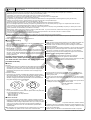
Kit Instruction Manual
Item No.:01−03−8010
Applicable models and frame No. (excluding the case of combo kit installation)
Monkey・Gorilla :Z50J-2000001 ∼
XR50R :AE03-1000001 ∼
:AB27-1000001 ∼ 1899999 CRF50F :AE03-1400001 ∼
Monkey BAJA
:Z50J-1700001 ∼
XR70R :DE02-1000001 ∼
Monkey R
:AB22-1000017 ∼
CRF70F :DE02-1700001 ∼
Monkey RT
:AB22-1007601 ∼
CD90 :HA03-1100005 ∼
☆ This product is applicable to CD90 engines
with the above-mentioned frame No.
CO
・Thank you for purchasing one of our products. Please strictly follow the following instructions in installing and using the products.
・Before fitting the products, please be sure to check the contents of the kit. Should you have any questions about the products, please kindly contact your dealer.
∼ Features ∼
○ This cylinder head, originally designed by us, is characterized by its unique appearance, completely different from the previous C-type engine. The new
head has an enlarged top diameter and a reduced stem diameter of both the intake and exhaust valves, with a new valve angle of nip and port shape.
We have incorporated roller bearings into the slipper of a valve rocker arm. The increased weight caused by incorporation of bearings is offset by adoption of an aluminum-forged rocker arm which consequently brings about higher power output at a high rotary area as a result of the synergy effect.
With a conventional C-type engine head, it is difficult to replace the cam shaft with the cylinder head being installed. However, with this Kit, the cam shaft
can be detached without removing the rocker arm, leaving the bearings on the oil line side of the cam shaft on the cylinder head side. Therefore, this makes
it easy to change the cam shafts even when the engine is mounted on the vehicle. Moreover, the new incorporation of the automatic decompression function into the camshaft makes it easy to press down on the kickstarter arm to the end, reducing strain on the kickshaft and gear.
Please read the following carefully before starting installation
PY
◎ Please note that, in some cases, the illustrations and photos may vary from the actual hardware.
◎ We do not take any responsibility for any accident or damage whatsoever arising from the use of the products not in conformity with the instructions in
the manual.
◎This kit is designed for exclusive use in the above-mentioned applicable models of motorcycles and frame numbers, and for exclusive use in motorcycles
equipped with a bore-up and bore-stroke exclusively for this kit as well. Therefore, please take note that this kit cannot be mounted on other applicable
models of motorcycles, or motorcycles not equipped with bore-up, etc exclusively for this kit.
◎Installation of this product requires removal and reinstallation of an engine, and disassembly of a clutch. Please prepare HONDA’s genuine service manual
for the above-mentioned applicable models, and work with enough care following instructions in the service manual. Besides, this instruction manual, as
well as HONDA’s service manual, is prepared for those who have acquired basic skill and knowledge in tuning. We recommend those who are technically
inexperienced or without right tools to ask a technically-trustworthy specialist shop to do the work.
◎ We shall be held free from any kind of warranty whatsoever of products other than this product if the glitch takes place on the other products than
this one after the installation and use of this product.
◎ You are kindly requested not to contact us about the combination of our products with other manufacturers’.
◎ A serial number is engraved on the cylinder head. You may be requested to inform us of the number when ordering parts.
◎ Bolts, and nats will be reused. However, be sure to replace worn-down or severely-damaged ones with new ones.
◎ Never use liquid packing. It may plug the oil passage, and in the worst case break the engine.
◎ Be sure to always use premium unleaded petrol. And make sure to check what kind of gasoline is remaining in the fuel tank. Whenever regular gasoline
is left in the fuel tank, always replace it with high-octane gasoline.
◎ Determine the heat value of a spark plug depending on how much it is burnt. In vehicles originally with a resistor plug, use a resistor plug.
◎ Never use this kit on the point-ignition system motorcycle.
◎Please be informed that what we can safely say is that the ignition system of this kit is compatible with ours and stock ignition systems, because no data
is available with us on the compatibility with other ignition systems. Therefore, please never use other ignition systems, which may cause technical troubles.
◎ As the stock clutch cannot be used, a centrifugal filter gets unavailable. Therefore, install an oil filter outside.
◎ Please install an oil cooler when necessary.
◎ Engine oil must be API SF or higher class, such as SAE 10W-40 / 15W-50, which are our recommendations.
◎ Change the sprocket with the one which meets the output and specifications.
◎ This kit cannot be used alone if you have purchased a cylinder head kit. If you have not purchased “our special engine parts”, please purchase special
parts with reference to the attached “Reference data on kit.”
◎ This kit is compatible with only those engine parts recommended by us. So, please replace the engine parts not recommended by us with those of our
recommendations.
◎ Since this kit is designed and developed for driving in closed races, do not use the kit for running on public roads.
◎ In case you have purchased this product as a combo kit, the above-mentioned applicable models vary depending on the type of drive sprocket.
◎ When the 124cc Kit is to be used together with a standard crankcase, the crankcase needs to be processed in the section where a sleeve is to be
attached. As we accept the processing, send the crankcase to us after carefully reading the instruction manual for your Cylinder Kit. Or, contact your
local specialist shop handling internal combustion products.
◎ We not recommend using stock crankcase with this kit. Because of stock crankcase will not hold the power of this kit.
Use Special crankcase Kit (100 / 106cc : 01-00-0038, 124cc : 01-00-0039, 138cc : 01-00-0040)
Important notice
Idling, sudden acceleration, and sudden engine braking will put a heavy load on the engine, which please note may result in crank shaft damage and
engine breakage in the worst case.
The following show the envisioned possibility of injuries to human bodies or property damages as a result of disregarding the following
Caution cautions.
・Since this kit is designed and developed for driving in closed races, do not use the kit for running on public roads.
・Work only when the engine and muffler are cool at below 35 degrees Celsius. Otherwise, you will burn yourself.
・Prepare right tools for the work. (Otherwise, improper work could cause breakage of parts or injuries to yourself.
・As some products and frames have sharp edges or protruding portions, please work with utmost care. (Otherwise, you will suffer injuries.)
・Always use new gasket and packing. (The worn or damaged parts may cause the engine troubles.)
- A’1 -
Dec./15/’
10
rev.Mar./25/’
11
rev.Apr./13/’
11
The following show the envisioned possibility of human death or serious injuries to human bodies as a result of disregarding the
Warning following cautions.
・Those who are technically unskilled or inexperienced are required not to do the work.
(Improper installation because of insufficient skill and knowledge could lead to parts breakage and subsequently to accidents.)
・Before doing work, secure the motorcycle on level ground for safety’s sake.
(Otherwise, your motorcycle could overturn and injure you while you are working.)
・Always start the engine in a well-ventilated place, and do not turn the engine on in an airtight place.
(Otherwise, you will suffer from carbon monoxide poisoning.)
・As gasoline is highly flammable, never place it close to fire. Make sure that nothing flammable is near the gasoline. (It may cause a fire.)
・Always use a torque wrench to screw bolts and nuts tight and securely to the specified torque.
(Improper torque could cause these parts to get damaged or fall off.)
・Never use the parts unspecified by us. (This may lead to parts breakage and consequent accidents.)
・If you find damaged parts when checking and performing maintenance, do not use these parts any longer, and replace them with new ones.
(The continued use of these damaged parts as they are could lead to accidents.)
・When you notice something abnormal with your motorcycle while riding down a road, stop riding immediately and park your motorcyle in a safe place. (Otherwise, the abnormaility could lead to an accident.)
・Before riding, always check every section for slack in parts like screws. If you find slack ones, screw them securely up to the specified torque.
(Or improper torque may cause parts to come off.)
・Check or perform maintenance of parts correctly according to the procedures in the instruction manual or a service manual.
(Improper checking or maintenance could lead to an accident.)
・Always use high-octane gasoline. (Otherwise, troubles such as engine knocking may cause accidents.)
CO
◎ Please be informed that, mainly because of improvement in performance, design changes, and cost increase, the product specifications and prices are
subject to change without prior notice.
◎ This manual should be retained for future reference.
●Cautions before riding:
●Revolution
① About fuel:
Whenever regular gasoline is remaining in the fuel tank, always replace it
with high-octane gasoline.
②With this kit installation, a centrifugal filter will be lost. So, please install a dry-type clutch with an external oil filter or a special clutch.
③ About change of a sprocket:
◇The installation of this kit will increase the power of your vehicle. So the use of a stock sprocket will result in severe wears of parts because of too
low gear, not only adversely affecting the engine life, but also breaking the
engine in the worst case. Therefore, please change the sprockets with the high-geared one.
◇Upper limt of revolutions varies depending on the installed cam shafts, etc.
Referring to the camshaft comparison graph on page A’3, install a
revolution counter to make sure that you drive the engine at revolutions below the upper limit.
◇Take note that idling and sudden acceleration in the 1st and the 2nd gears
particularly tend to exceed the upper limit of revultions. Over revolutions will result in nonsmooth revolutions of the engine, not only adversely affecting the engine life, but also breaking the engine in the worst case.
PY
This kit cannot function on its own. Referring to the
attached sheet, please purchase a kit for exclusive
use with this kit. This does not apply if you have
purchaed a full kit.)
● Others:
Oil cooler:
◇ The installaiton of this kit increases the heat release value of the engine,
set off by the increase in power. For a long-time and high load running, we
recommend you to install an oil cooler kit which keeps oil at appropriate temperatures and prevents such troubles as oil film shortage at high
temperatures.
Carburetor manifold:
◇ The surface of a manifold, compatible with R-Stage & old Super Head, with a port diameter of φ24∼φ25 on the side of an inlet pipe, will not be
level with the cylinder head because of the difference in manifold
diameter. Enlarging the manifold’s port diameter on the manifold side will bring about smoother output characteristics.
φ 25 →φ 26
24
φ
◇ This Super Head has optional titanium valve spring retainers.
Titanium retainers are about 30% lighter than steel retainers.
The surface is treated with a special coating of which hardness is HV1000
above for added shock-resistance and wear-resistance.
Item No.01-12-084 (2 pcs)
● A serial number is punched on the cylinder head just for the sake of administration. You may be requested to inform us of the number when ordering repair parts.
In case you are not able to order parts because you do not have the repair
parts numbers or for other reasons, please place an order in the following
way.
☆ Make a note of the number punched on the left side of the cylinder head.
Example of how to order → Super head kit, repair
head No.-2SM-00001 → Intake valve Qty: 1 piece
1
φ
φ
∼
25
●Titanium valve spring retainer (optional)
26
2SM-00001
A head No. (2SM-00***)is stamped here
◇ We advise you to use a special carburetor kit for Super Head+R.
For the part numbers of the carburetor kits, please refer to the parts list of
our recommendations on page 3.
・Special manifold only for Super Head+R
VM26: 003-02-2541
PE28 : 003-02-2551
● About camshaft:
◇If you have purchased a cylinder head kit, a special camshaft is needed separately. Camshafts with a few kinds of profiles are available from us to
meet different uses and engine displacement. Even if you have purchased
a full kit, you can study to use them as an optional extra in addition to camshafts inclued in the full kit. For more information, please refer to enclosed paper.
● An inspection cap and a breather cap are included in this kit. In case you
use a breather cap, please use an oil catch tank at the same time.
● For those who have purchased a cylinder head alone, selection sets are
available to meet your combination demand for engine displacement, etc.
Please study the required contents of the kit, referring to “Reference data
on kit” on enclosed paper.
Please contact your dealer for more details about the kit or enquiries.
- A’2 -
Dec./15/’
10
rev.Mar./25/’
11
rev.Apr./13/’
11
● Engine parts of our recommendations:
☆ Camshaft comparison data list
※This kit is only compatible with those engine parts recommended by us. So, please replace the parts not of our recommendations with those of our recommendations.
Note: As these are the data measured on a Dyno Jet, the data differ from the actual driving. Please refer to them just for a reference. The engine power varies significantly depending on the temperatures.
● 88 cc
Parts of our recommendations
Test Vehicle : MONKEY 52X41.4 88cc Carburetor:MIKUNI VM26 Exhaust:Racing Muffler
Special clutch kit
14
Dry-type clutch kit
SAE Power(PS)
Clutch
Stock C.D.I.
CO
Hyper C.D.I.
07-02-15
C.D.I. Magnet
05-02-0511
MONKEY
88cc
106cc
124cc
12
20 cam
Mikuni VM26
03-05-0484
carburetor kit
10
Keihin PE28
03-05-0981
carburetor kit
8
Mikuni VM26
03-05-0482
carburetor kit
138cc
Carburetor
MONKEY-R
88cc
106cc
Keihin PE28
03-05-098
carburetor kit
4
Mikuni VM26
03-05-0484
carburetor kit
2
3
5
6
7
8
9
10
11
12
13
12
138cc 01-14-0006
10
Oil catch tank (Only for the Monkey/Gorilla)
Oil catch return tank kit
(Only in case a head breather cap is used.)
Oil catch tank kit
01-16-0051
SAE Power(PS)
88cc
01-14-0002
106cc
High-duty cam chain kit 124cc 01-14-0003
25 cam
PY
35 cam
15 cam
07-05-0010
09-04-032
8
☆ It’s impossible to install this product to a CD90 motorcyle because there is no compatible carburetor. Please take note that this product is applicable to engines with
the above mentioned CD90 frame No. only.
6
4
2
RPM(×1000)
0
○The following camshafts compatible with this Kit are available from us. Referring to the below-mentioned output graphics, please select a camshaft to match your usage
and engine displacement for your great riding pleasure.
3
19
18
Packed together with Monkey / Gorilla Bore Stroke Up (124)
17
S-25D camshaft 01-08-0104
Packed together with Monkey / Gorilla Bore Stroke Up (138)
option
6
7
8
9
10
25 cam
11
12
13
14
15
35 cam
Test Vehicle : MONKEY 54X54 124cc Carburetor:KEIHIN PE28 Exhaust:Racing Muffler
20
Packed together with Monkey / Gorilla (88/106) Packed together with CD90
S-35D camshaft 01-08-0106
5
● 124 cc
S-20D camshaft 01-08-0103
option
4
15 cam
S-1D5 camshaft 01-08-0102
S-30D camshaft 01-08-0105
15
Test Vehicle : MONKEY 52X41.4 88cc Carburetor:MIKUNI VM26 Exhaust:Racing Muffler
Cam chain
(Only in case of a cylinder head kit)
option
14
30 cam
20 cam
14
Super oil pump kit
● About optional camshafts
4
12 cam
Oil pump
S-12D camshaft 01-08-0101
R PM(×1000)
0
Mikuni VM26
03-05-3245
carburetor kit
CRF50
30 cam
6
Keihin PE28
03-05-095
carburetor kit
124cc
12 cam
SAE Power(PS)
Ignition system
16
15
30 cam
20 cam
12 cam
14
13
12
11
The bigger the numbers of XX / YY are, the wider the durations are. With these camshafts, the output power will produce more to high rpm range. While, the smaller the
numbers are, the narrower the durations are. With these camshafts, the output power will
produce more to low-to-mid rpm range. We supply the suitable camshaft depending on
the displacements.
10
9
8
7
6
5
4
3
When choosing the optional camshafts, please choose the camshaft referring to the
2
1
camshaft data chart to suit your riding purpose.
RPM(×1000)
0
Also, the engine output will vary significantly depending on the using exhaust system,
2
5
6
7
8
9
10
11
12
13
14
12 cam
20 cam
Test Vehicle : MONKEY 54X54 124cc Carburetor:KEIHIN PE28 Exhaust:Racing Muffler
20
19
pressure.
4
30 cam
length of inlet pipe, carburetor diameter, compression ratio, ignition system, ignition
timing, fuel or natural phenomenons such as ambient temperature or atmospheric
3
SAE Power(PS)
○ About Camshafts Number
18
17
16
15
35 cam
25 cam
15 cam
14
13
12
11
10
9
8
7
6
5
4
3
2
1
RPM(×1000)
0
2
3
4
35 cam
- A’3 -
5
6
25 cam
7
8
9
10
11
12
13
14
15 cam
Dec./15/’
10
∼ Kit Contents ∼
18
18
10
18
18
14
11
CO
9
16
16
1
G
26
15
Head number punched here
13
E
19
3
C
H
L
F
D
B
A
22
23
2
22
23
21
23
24
2
22
23
I
※5
C
M
00―01―0021
D
H
PY
K
E
F
J
7
6
4
13
25
G
10
6
12
16
16
16
8
17
20
16
∴ Please note that in ordering repair parts, be sure to quote the Repair Part Item No. Otherwise, we may not be able to accept your orders.
There are some parts, however, for which we are not in a position to accept your order in just the quantity to be used. In this case, please take them in
the quantity packed.
01―13―8002
00―01―1025
00―01―1026
9
13
10
13
00―00―0041
00―00―0160
16
00―00―0288
18
16
18
14
13
12
15
16
01―08―0001
17
18
16
16
18
16
Inspection cap screw set Right side-cover screw set Left side-cover screw set
12
8
17
13
No.
1
2
3
4
※5
6
7
8
9
10
11
12
13
14
15
Parts Name
Cylinder head COMP.
Rocker arm COMP.
Rocker arm shaft
Cam sprocket
Cam gear washer
Cap screw, 5x12
Cam shaft circlip
Left side-cover
Breather cap
Inspection cap
Right side-cover
Left side-cover O-ring
Inspection cap O-ring
O-ring, 15 mm
Right side-cover O-ring
Qty
1
2
1
1
1
2
1
1
1
2
1
1
2
1
1
Repair parts No.
06120-2SM-T00
14431-SPH-T01
14451-SPR-T00
00-01-0099
00-01-0022 (with a bolt)
00-00-0066
00-01-0081
01-08-0001
Symbol
A
B
C
D
E
F
G
Parts Name
Intake valve
Exhaust valve
Valve spring outer seat
Valve stem seal
Valve spring (outer)
Valve spring (inner)
Valve spring retainer
Qty
1
1
2
2
2
2
2
Repair parts No.
14711-SPH-T01-F
14721-SPH-T01-F
00-01-0002
00-01-0015
11121-SPH-T01
01-13-8002
01-12-0101
00-01-0078
Qty
1
1
1
1
1
4
3
1
1
3
3
6
3
Qty
1
1
2
2
2
2
2
No.
16
17
18
19
20
21
22
23
24
25
26
Tool
Tool
Tool
Symbol
H
I
J
K
L
M
Parts Name
Cap screw, 5x15 (SUS)
Cap screw, 5x10 (SUS)
Cap screw, 5x12 (SUS)
Manifold gasket
Exhaust pipe gasket
Copper sealing washer
Sealing washer
Cap nut, 6 mm
Cap screw, 6x18
Dowel pin, 8x12
Socket set screw, 6x15
Alumi Special (5 g)
Hex wrench, 3 mm
Hex wrench, 4 mm
Hex wrench, 5 mm
Qty
6
1
4
1
1
1
3
4
1
1
2
1
1
1
1
Repair parts No.
00-00-0041
00-00-0233
00-00-0160
00-03-0009
00-01-0064
00-01-0029
00-00-0344
Parts Name
Valve cotter
Radial ball bearing
C-shaped ring
Stud bolt, 6x32
Over-sized valve guide, IN
Over-sized valve guide, OUT
Qty
4
2
1
2
1
1
Repair parts No.
00-01-0018
00-00-0156
00-00-0153
00-00-0162
00-01-0001
00-01-0084
00-01-0085
00-00-0165
00-01-0332
16
16
Qty
4
3
4
3
2
4
4
4
2
2
1
Qty
4
1
1
2
1
1
Item No. marked with an ※ is not used when an automatic decompression camshaft is to be installed.
Co.,Ltd.
3-5-16 Nishikiorihigashi Tondabayashi Osaka Japan
- A’4 -
TEL : 81-721-25-1357 FAX : 81-721-24-5059 URL : http://www.takegawa.co.jp
Dec./15/’
10
∼ Cylinder Head Installation Procedures ∼
○ Removethe rocker arm shaft and
adjusting bolts and nuts on the original cylinder head.
○Fix 8x14 dowel pins of the kit into the dowel pin holes on the cylinder.
CO
OIL
the specified torque.
T : 12N・m (1.2kgf・m)
○Fix the cam chain so it will not fall into the crankcase.
NEW
○ Tighten a cam chain guide roller
of the cylinder to the specified torque.
PY
∴ Please use appropriate gasket.
Note: These cylinders have a
marking on the cylinder head
surface or its Item No. is stamped on the fin side.
Item No.
stamped
here
○ Fix the rocker arms to the Super
Head.
Apply molybdenum solution to the
original rocker arm shaft, and fix it
on the exhaust side.
Apply molybdenum solution to a
rocker arm shaft of the kit as well,
and fix it with its slit part pointing
to the cam chain side.
Marking
MO-OIL
Item No.
stamped here
○ Tighten the side bolt on the
cylinder side and the cap screws
on the cylinder head side to the specified torque.
CAUTION : Be sure to tighten to
○ Thoroughly degrease the upper surface of the cylinder.
○ For V, H, S (SCUT) cylinder: use 0.25mm head gasket.
○If you find the removed adjust bolt
& / or adjust nut damaged, replace
it / them with (a) new one(s).
○ Apply engine oil to the removed
adjusting bolts, and fixthese bolts
to rocker arms of the kit.
○ Set the piston at the top dead
center position, and install the
cylinder head.
○ After applying Alumi Special a little
to the threaded part of the cylinder
head stud bolts, fix a copper washer
of the kit to the lower-left part (oil line) and washers of the kit to other
parts. Then fix four cap nuts of the
kit and 6x18 cap screws as
indicated in the figure below, and loosely tighten them.
Copper sealing
washer
CAUTION : Be sure to tighten to
the specified torque.
T : 10N・m (1.0kgf・m)
○ Align a “T” mark on the flywheel
with an alignment mark on the crankcase. Then set the piston at
TDC (Top Dead Center).
○ Apply engine oil to a bearing on
the camshaft COMP., which please fit to a cylinder head. And
put a provided 8x12 dowel pin into
the center hole in the camshaft.
Marking
Cap screw
○ No parts number stamped on your
cylinder, (or cylinder uses green O ring) please use 1.0mm(3 pcs metal)
head gasket with green O-ring and
black rubber gasket.
The above applies only
to the old-type cylinder kits.
○ Tighten nuts on the stud bolt
diagonally to the specified torque in
a few steps.
CAUTION : Be sure to tighten to the
specified torque.
T : 12N・m (1.2kgf・m)
NEW
MO-OIL
Included part for intake side
Dowel pin 8 x 12
NOTE : The supplied dowel pin will
not be used in case a dowel
pin is pressed into your camshaft.
∴ Please use appropriate gasket.
- B ’1 -
Dec./15/’
10
rev.Feb./21/’
11
○ Fix a cam shaft circlip of the kit,
and fix the cam shaft.
At this stage, set the location of
ring end gap of the circlip not to meet the notch on the cylinder head
cam hole.
●In case you install an
automatic decompression
cam shaft:
○Set a cam sprocket washer through
a weight, and set two black 5x12 cap screws into upper and lower
holes.
CO
Weight
5x12
○ Attach a snap ring in the shaft groove.
CAUTION : Do not expant the snap ring more than necessary.
WARNING : Always use a new snap ring at any time,
and do not reuse it.
●When installing an
automatic decompression
cam shaft:
○Adjust the valve clearance on the
EX side with the shaft of the
camshaft being pulled toward you
so that the decompression
function can be deactivated.
NEW
5x12
Cam sprocket washer
Notch
○Check that the circlip is right in the circlip groove.
Warning : Do the checking
without fail.
○Remove the side bolt on the cam
chain tensioner.
○ Attach the cam chain to the cam
sprocket, and fix them with a cam
sprocket plate and two 5x12 (black) cap screws included in the
kit.
(At this point, apply Alumi Special
a little to the threaded parts of the
cap screws.)
Then align the “T” mark on the
flywheel with the alignment mark
on the crankcase, and align an “O” mark on the cam sprocket with
the alignment mark on the
cylinder head.
Marks
○ Attach the camchain to the cam sprocket. And place the weight to
face the “O” mark and install it with
two black 5x12 cap screws.
(At this time, apply a thin coat of
Alumi Special, the heat-resistant
lubricating agent, to the thread of the
cap screw.) Then, align the “T” mark
on the flywheel with the alignment
mark on the crankcase, aligning the
“O” mark on the cam sprocket with
the alignment mark on the cylinder
head.
○Tighten the adjusting nut to the specified torque.
○ Apply engine oil a little to two kinds
of O-rings for the right side cover,
and fix them to the right side cover.
Then tighten them with 5x12 cap screws of the kit to the specified torque.
CAUTION : Be sure to tighten to
the specified torque.
T : 10N・m (1.0kgf・m)
PY
CAUTION : Be sure to tighten to the
specified torque.
T : 6N・m (0.6kgf・m)
NEW
Marks
○ Unfasten the thumb screw.
○ Holding the crank, tighten the cap
screws, which are attached to fix
the cam sprocket, to the specified
torque.
CAUTION : Be sure to tighten to the
specified torque.
T : 10N・m (1.0kgf・m)
○Check that the “T” mark on the
flywheel is aligning with an
alignment mark on the crankcase.
○ Adjust the valve clearance with an
○Check that the “T” mark on the
flywheel is still aligned with the “O”
mark on the cam sprocket.
○ Pass a 6mm snap ring and a plate
into a thumb screw supplied in the
Camshaft Kit, attach it to the shaft
tip of the camshaft comp. and pull the shaft toward you.
adjust screw.
IN : 0.05 ∼ 0.08 (when cold)
OUT : 0.05 ∼ 0.08 (when cold)
○Apply engine oil a little to a left- side-cover O-ring of the kit, and
fix it to the left side cover. Then fix
them to the cylinder head with two
5x15 cap screws and with a 5x10
cap screw of the kit and tighten
them to the specified torque. (Be
careful of the location of screws.)
CAUTION : Screws must be used
at the specified
positions only.
CAUTION : Be sure to tighten to
the specified torque.
T : 6N・m (0.6kgf・m)
NEW
5X15
5X15
5X10
- B’2 -
Dec./15/’
10
○After applying engine oil a little to
○ Install socket set screws of the kit
an O-ring on the inspection cap of
the kit, attach the O-ring to the
inspection cap, and fix the
inspection cap with 5x15 cap screw of the kit, and tighten up the screw to the specified torque.
to two taps on the cylinder head ports which will not be used for manifold installation, and tighten them to the specified torque.
CAUTION : Be sure to tighten to the
specified torque.
T : 5N・m (0.5kgf・m)
CO
● In case a breather cap is used:
○Apply engine oil a little to insection
cap O-rings of the kit, and fix them
to the breather cap and the
inspection cap. Then fix and tighten the breather cap on the intake side and the inspection cap
on the exhaust side with 5x15 cap
screws of the kit to the specified
torque.
CAUTION : Be sure to tighten to
the specified torque.
T : 6N・m (0.6kgf・m)
NEW
These taps will
not be used.
○Following the instruction manual for
the relative carburetor, install the carburetor.
●When installing an
☆ In the case of a three-point
support crank shaft (3B) kit, fix a automatic decompression
cam shaft:
generator cover according to ※ When starting the engine, keep
crank-kit installation
the stroke of the kickstarter arm
instructions.
○ In case you use a breather cap, fix
a breather hose according to
oil-catch-tank installation
instructions.
∴ In case you use a breather cap, fix
a breather hose according to
oil-catch-tank installation
instructions.
・Item No. for a blade hose set
(1 m, with clips)
: 000-03-054
CAUTION : Be sure to tighten to the
specified torque.
T : 12N・m (1.2kgf・m)
☆ Engine Starting ☆
PY
○ Check that the ignition key and the
fuel cock are turned OFF.
○Continue kicking the starter for a while to circulate the engine oil all around the engine.
○Install the spark plug. Apply Alumi CAUTION : Be sure to tighten to the
specified torque.
○ Install the generator cover.
CAUTION : Be sure to tighten to
the specified torque.
T : 8N・m (0.8kgf・m)
CAUTION : Be sure to tighten to the
specified torque.
T : 7 ∼ 11N・m
(0.7 ∼ 1.1kgf・m)
Thermal value
CAUTION : Be sure to follow the
instructions in the manual.
○ With reference to the service manual, attach the drive chain.
○ Check for any abnormality such
as an abnormal sound.
○ If nothing abnormal is detected,
carry out a shakedown for about
30 to 50 km, and check the valve
clearance again.
CAUTION: Work only when the
engine and the
muffler are cool.
○ After the shakedown, double- check for any abnormality such
as an abnormal sound and blow by gas.
NGK :CR8HSA
○ Add engine oil in amount specified
by the clutch kit you use.
Take the sufficient
stroke amount.
○ Carry out a shakedown again for
about 100 to 150 km.
Designated plug
○ With reference to the service manual, mount the engine on the
frame.
the engine, taking sufficient stroke
amount.
○ Install the drive sprocket.
Special a little to the threaded part
of the plug, and fix it.
○Pour engine oil from the side bolt
hole in the cam chain tensioner,
and tighten the side bolt.
wide enough.
Usually, the stroke amount of the
kickstarter arm becomes short
especially when a dry-type clutch
is installed onto the engine, which
makes it hard to start the engine.
Adjust the angle at which to
install the kickstarter arm, and start
(If any abnormality is detected, disassemble the engine again and
check each section.)
WARNING: Never re-use parts
which cannot be
re-used.
DENSO:U24FSR―U
Thermal value
○Attach the plug cap to the spark plug.
○ Wipe off the dirt and dust on the engine.
○ Turn ON the fuel cock and ignition
key, and start the engine.
WARNING: Work only in a
well-ventilated place.
- B ’3 -
Dec./15/’
10
CO
INSPECTION / SERVICE LIMITS
WARNING
Since this cylinder head manual is prepared for those who have acquired basic skills and knowledge in tuning, those who are technically unskilled or inexperienced are
required not to do the work.
●After the disassembly of the hardware and a cylinder head, clean them before the inspection and measuring. And then, blow them with compressed air, and dry them well.
●Engine oil for lubricating the camshaft will be supplied through the oil passage in the cylinder head. Clean the oil passage before assembling the cylinder head.
●After the disassembly of hardware, put a mark on the hardware so they can be reinstalled correctly to their original position.
Reference Value List for Cylinder Head Maintenance
PY
Items
Standard
Valve clearance (intake)
0.05∼0.08mm (when cold)
(exhaust)
0.05∼0.08mm (when cold)
Cylinder head distortion
Inside diameter of valve rocker arm
Outside diameter of rocker arm shaft (intake / exhaust)
Clearance between a rocker arm and a shaft
0.013∼0.037mm
Inside diameter of valve guide (intake)
(exhaust)
Outside diameter of valve stem (intake)
(exhaust)
Clearance between a valve stem and a guide (intake)
0.01∼0.037mm
(exhaust)
0.025∼0.052mm
Valve seat contact width (Intake)
0.8∼1.0mm
(exhaust)
1.0∼1.2mm
Free length of valve spring (outer)
(inner)
Service Limit
Remarks
0.05mm
10.05mm
9.92mm
0.10mm
4.56mm
4.57mm
4.47mm
4.45mm
0.09mm
0.12mm
1.5mm
1.7mm
33mm
28.5mm
Modify or replace
Replace
Replace
Replace
Replace the guide or the head
Replace the guide or the head
Replace
Replace
Replace the guide or the head
Replace the guide or the head
Modify or replace the head
Modify or replace the head
Replace
Replace
○Special tool : Valve spring compressor set of Item No. 00-01-1005
○Torque unit
1 kgf・m = 9.80665 N・m (=newton meter)
M O - O I L ○This mark shows molybdenum solution.
This solution is a mixture of molybdenum grease and engine oil (in the ratio of 1:1).
∴Apply molybdenum solution or assembly paste to the portions where it is indicated that molybdenum solution needs to be applied.
NEW
○This mark shows those parts to be replaced with every overhaul.
Do not fail to replace these parts every time they are overhauled.
AL-SPL
○This mark means Alumi Special (heat-resistant lubricating agent).
・Alumi Special = heat-resistant lubricating paste and grease which prevent galling from high temperatures and heavy loading, and adhesion.
(Purpose: good for those parts which get hot like a spark plug and exhaust manifold. )
☆Never apply this to any parts other than the specified parts.
-C1-
CO
INSPECTION / SERVICE LIMITS
●Splitting of Valve
・Compress the valve spring, using a valve spring
compressor.
CAUTION: Never compress it more than necessary.
Check each valve for bending, baking, and
Inspection of Valve Seat
damages.
・Measure the exterior diameter of the valve stem at
・Remove carbon sediment in the cylinder head
combustion chamber and valve.
the sliding surface of the guide with a micrometer.
・Dissolve red lead primer with oil or the like, and apply
Service Limit
∴Special tool: Valve spring compressor set of
item No. 00-01-1005
IN : 4.47 mm
EX: 4.45 mm
it to the valve face evenly.
Replace the bent, baked or damaged valves with
new ones.
Valve spring
compressor
・Removal of Valve Cotter
Use a magnet to remove the cotter if it does not come
off easily.
・Remove first the valve spring compressor, and then the following parts:
・Valve spring retainer
・Valve spring (Inner & Outer)
PY
Inspection of the Valve Guide.
・Measure the inner diameter of the valve guide.
Service Limit
IN : 4.56 mm
EX: 4.57 mm
Replace the valve guide or cylinder head if the valve guide is scratched or damaged.
・Valve
Valve
Inner spring
Outer spring
Valve spring
retainer
Valve cotter
Outer diameter of the valve stem subtracted from the
CAUTION: If the valve is damaged at its end, do not remove it forcibly, but rectify the end first before removing it.
-C2-
inner diameter of valve guide is a guide clearance.
Service Limit
IN : 0.09 mm
EX: 0.12 mm
・Strike the valve once and lightly with a valve punner,
and rotate it.
・Wipe off the red lead primer on the valve faces, and strike the valves once and lightly with the valve punner
without rotating them, and check the contact surfaces
for damages or scratches.
Valve
punner
CO
INSPECTION / SERVICE LIMITS
Inspection of Rocker Arm:
Inspection of Valve Spring Retainer
・Check the rocker arms for scratches, damages and
jamming. And check if the bearing rotates smoothly.
・Inspect the contact surface of valve spring and retainer
or keepers.
・Measure the internal diameter of the rocker arms.
・If they are in good condition, they may be reused.
・Unfasten an adjust bolt, and check it for scratches.
If it is scratched, change it with a new one.
Uneven seat width
Contacting at
a low position
Contacting at
a high position
10.05 mm, replace the rocker arm.
Inspection of Rocker Arm Shaft
・Check the rocker arm shaft for bending, scratches, and damages.
・Measure the external diameter of the rocker arm shaft.
∴Service limit : If the external diameter is smaller ・Check the valve springs for scratches and damages.
・Measure the free length of the valve springs.
∴Outer : If the length is below 33, replace them.
Inner : If the length is below 28.5, replace them.
than 9.92 mm, replace it.
Service Limit:
Need to be fixed when the service limit at IN is more
than 1.5 mm and when the service limit at EX is more
than 1.7 mm.
・If there is a scratch on the valve seat, modify the seat.
・If the contact width is wide, narrow, in a high or low
position, modify the seat.
・Ask machine shop for modification.
below 28.5
PY
Service limit : If the inner diameter is bigger than
Inspection of Valve Spring
below 33
Scratch on
the seat
Replace as necessary.
Inspection of Camshaft
・Check the camshaft for scratches, cracks, and
damages.
Outer diameter of the rocker arm shaft subtracted from
the inner diameter of rocker arm is a clearance.
∴Service limit : If the clearance is bigger than
0.1 mm, replace the rocker arm shaft.
-C3-
CO
INSPECTION / SERVICE LIMITS
Inspection of the Camshaft Bearing
・Rotate the outer race of the bearings with fingers.
・Slide the slide shaft, and check if the decompression
pin moves up and down on the EX side cam.
Inspection of the bearing
・Take out the C-shaped ring from the cylinder head and
If the outer race does not rotate smoothly or if it is
rickety, replace either the ball bearing or cam shaft.
If the pin does not move up and down when you slide
the shaft, or the shaft does not slide because it has
remove the ball bearing.
become stuck, then change the cam shaft.
Up & down
Slide
Slide shaft
・In the case of automatic decompression camshaft:
Pull the slide shaft of the camshaft center.
And compress the spring in the shaft, and release the
shaft. Then, check if the slide shaft slides smoothly
and slides back to its original position.
If the slide shaft does not slide smoothly or the
tension is not on the spring of the slide shaft, change
the camshaft.
Slide shaft
Pin
PY
・Rotate the bearing race with fingers. If it does not
rotate smoothly or if it is rickety, replace the bearing.
Inspection of Cylinder Head
・Check the spark plug hole and valve hole for the cracks
in the vicinity.
Check the cylinder head for distortion with a straight
edge and thickness gauge. Straight edge
Thickness gauge
Service limit: If the distortion is over 0.05 mm, rectify
or replace the cylinder head.
-C4-
CO
INSPECTION / SERVICE LIMITS
Installation of Bearing
・Install the bearing to the cylinder head with the shield
facing the camshaft.
・Install the C-shaped ring with its round portion facing
the bearing.
Direction of the round face
・To the head, attach the valve spring, with a narrowly pitch side pointing to the combustion chamber.
CAUTION: Be sure to place the narrower-pitched
portion of the valve spring to face the
combustion chamber side.
PY
Combustion
chamber
Direction of the shield
Narrower
・Compress the valve spring with a valve spring
compressor. And apply a thin coat of grease to valve
cotters, and install them.
●Valve Assembly:
・Install valve spring seats and new valve stem seals.
・Apply molybdenum solution to the sliding surfaces of
the valve stems, and fit the valves into the valve guides,
rotating valves slowly with care not to damage the stem
seals.
Valve
Valve
MO-OIL
MO-OIL
Stem seal N E W
Stem seal N E W
Valve spring, inner
CAUTION: Do not compress the valve spring more than
necessary.
・Strike lightly the end of valve stems a few times so the
valves and cotters fit together well.
CAUTION: Be careful not to damage the valves.
Spring seat
Valve spring, outer
Valve spring retainer
Valve cotter
-C5-
01―03―8010
01―03―8011
01―03―8006
01―03―8007
camshaft
camshaft
camshaft
camshaft
camshaft
camshaft
STD
Select a cam
01-08-0101
01-08-0102
01-08-0103
01-08-0104
01-08-0105
01-08-0106
AUTO DECOMP
S-12D camshaft
S-15D camshaft
S-20D camshaft
S-25D camshaft
S-30D camshaft
S-35D camshaft
r
ylinde
H88 c
01―04―8088H φ52鋳鉄スリーブシリンダー 52mm cast iron sleeve cylinder
r
ylinde
V88 c
01―04―8088V φ52鋳鉄スリーブシリンダー 52mm cast iron sleeve cylinder
01―04―8002 φ57メッキシリンダーSCUT 57mm SCUT plated cylinder
nder
T cyli
SCU
☆01―03―8010・01―03―8011・01―03―8006・01―03―8007シリンダーヘッドキットのみで購入された
場合、この参照表にて専用パーツを検討して下さい。(CD90除く)
If you have purchased a cylinder head kit only (Item No. 01-03-8010・01-03-8011・01-03-8006・01-03-8007), please study to install these
special parts referring to this reference data. (except CD90)
rev.Mar./25/’
11
Dec./14/’
10
ボアアップ参照表(88cc、106cc)
Reference data on bore- up kit (88cc,106cc)
01-08-0012
01-08-0015
01-08-0020
01-08-0025
01-08-0030
01-08-0035
V又はHシリンダー選択
Select a V or H cylinder
PY
カムを選択
S-12
S-15
S-20
S-25
S-30
S-35
88cc
106cc
CO
01―03―8010
01―03―8011
01―03―8006
S-12
S-15
S-20
S-25
S-30
S-35
camshaft
camshaft
camshaft
camshaft
camshaft
camshaft
S-12D camshaft
S-15D camshaft
S-20D camshaft
S-25D camshaft
S-30D camshaft
S-35D camshaft
01-08-0012
01-08-0015
01-08-0020
01-08-0025
01-08-0030
01-08-0035
01-08-0101
01-08-0102
01-08-0103
01-08-0104
01-08-0105
01-08-0106
01―10―0115
ボア&ストローク参照表(100cc)
Reference data on bore- & stroke kit (100cc)
01―04―0122 メッキシリンダーSCUT SCUT plated cylinder
39mmストローク
39mm stroke
01―10―0116
01―14―0002
If you have purchased a cylinder head kit only (Item No. 01-03-8010・01-03-8011・01-03-8006・01-03-8007), please study to install these
special parts referring to this reference data. (except CD90)
☆01―03―8010・01―03―8011・01―03―8006・01―03―8007シリンダーヘッドキットのみで購入された
場合、この参照表にて専用パーツを検討して下さい。(CD90除く)
01―03―8007
STD
カムを選択
Select a cam
AUTO DECOMP
PY
CO
rev.Mar./25/’
11
Dec./14/’
10
01―03―8010
01―03―8011
01―03―8006
S-12
S-15
S-20
S-25
S-30
S-35
camshaft
camshaft
camshaft
camshaft
camshaft
camshaft
S-12D camshaft
S-15D camshaft
S-20D camshaft
S-25D camshaft
S-30D camshaft
S-35D camshaft
01-08-0012
01-08-0015
01-08-0020
01-08-0025
01-08-0030
01-08-0035
01-08-0101
01-08-0102
01-08-0103
01-08-0104
01-08-0105
01-08-0106
er
cylind
V106
01―04―8106VA メッキシリンダー
01―04―8106V 鋳鉄スリーブシリンダー
Plated cylinder
Cast iron sleeve cylinder
01―10―8432T
01―10―8432
01―14―0002
05―02―0011AL
3点支持クランクシャフト―50mmストローク(3B)
Three-point supporting crank shaft-50mm stroke (3B)
50mmストローク(2B)
50mm stroke (2B)
クランクケース加工必要 Require crankcase modification
01―10―0071T
01―14―0002
01―10―0071
If you have purchased a cylinder head kit only (Item No. 01-03-8010・01-03-8011・01-03-8006・01-03-8007), please study to install these
special parts referring to this reference data. (except CD90)
rev.Mar./25/’
11
Dec./14/’
10
ボア&ストロークアップ参照表(106cc)
Reference data on bore- & stroke-up kit (106cc)
01―04―8106H 鋳鉄スリーブシリンダー Cast iron sleeve cylinder
er
cylind
H106
2B又は3Bクランク選択
Select a 2B or 3B crank
PY
CO
☆01―03―8010・01―03―8011・01―03―8006・01―03―8007シリンダーヘッドキットのみで購入された
場合、この参照表にて専用パーツを検討して下さい。(CD90除く)
01―03―8007
STD
カムを選択
Select a cam
AUTO DECOMP
V又はHシリンダー選択
Select a V or H cylinder
01―03―8010
01―03―8011
01―03―8006
S-12
S-15
S-20
S-25
S-30
S-35
camshaft
camshaft
camshaft
camshaft
camshaft
camshaft
S-12D camshaft
S-15D camshaft
S-20D camshaft
S-25D camshaft
S-30D camshaft
S-35D camshaft
01-08-0012
01-08-0015
01-08-0020
01-08-0025
01-08-0030
01-08-0035
01-08-0101
01-08-0102
01-08-0103
01-08-0104
01-08-0105
01-08-0106
01―04―8124V 鋳鉄スリーブシリンダー Cast iron sleeve cylinder
er
cylind
V124
01―10―8042T
Three-point supporting crank shaft-54mm stroke
3点支持クランクシャフト―54mmストローク
05―02―0011AL
54mmストローク
54mm stroke
01―10―0091T
01―14―0003
01―10―0091
01―14―0003
01―10―8042
rev.Mar./25/’
11
Dec./14/’
10
ボア&ストロークアップ参照表(124cc)
Reference data on bore- & stroke-up kit (124cc)
鍛造ピストン
Forged piston
01―04―8013
メッキシリンダー Plated cylinder
r
ylinde
124 c
01―04―8124H メッキシリンダー Plated cylinder
nder
4 cyli
HA12
2B又は3Bクランク選択
Select a 2B or 3B crank
PY
CO
☆01―03―8010・01―03―8011・01―03―8006・01―03―8007シリンダーヘッドキットのみで購入された
場合、この参照表にて専用パーツを検討して下さい。(CD90除く)
If you have purchased a cylinder head kit only (Item No. 01-03-8010・01-03-8011・01-03-8006・01-03-8007), please study to install these
special parts referring to this reference data. (except CD90)
01―03―8007
STD
カムを選択
Select a cam
AUTO DECOMP
シリンダー選択
Select a cylinder
01―03―8010
01―03―8011
01―03―8006
01-08-0012
01-08-0015
01-08-0020
01-08-0025
01-08-0030
01-08-0035
01―04―0125 φ52鋳鉄スリーブシリンダー 52mm cast iron sleeve cylinder
01―02―0114
01―04―0106H φ54メッキシリンダー φ54 Plated cylinder クランクケース加工必要 Require crankcase modification
r
ylinde
113 c
r
ylinde
105c
01―02―0114
rev.Mar./25/’
11
Dec./14/’
10
CD90エンジン用 ボアアップ参照表
Reference data on bore- up kit For a CD90 engine
camshaft
camshaft
camshaft
camshaft
camshaft
camshaft
STD
カムを選択
Select a cam
01-08-0101
01-08-0102
01-08-0103
01-08-0104
01-08-0105
01-08-0106
AUTO DECOMP
S-12D camshaft
S-15D camshaft
S-20D camshaft
S-25D camshaft
S-30D camshaft
S-35D camshaft
If you have purchased a cylinder head kit only (Item No. 01-03-8010・01-03-8011・01-03-8006・01-03-8007), please study to install these
special parts referring to this reference data. (except CD90)
☆01―03―8010・01―03―8011・01―03―8006・01―03―8007シリンダーヘッドキットのみで購入された
場合、この参照表にて専用パーツを検討して下さい。(CD90除く)
シリンダー選択
Select a cylinder
01―03―8007
S-12
S-15
S-20
S-25
S-30
S-35
113cc
105cc
PY
CO
01―03―8010
01―03―8011
01―03―8006
01―03―8007
S-12
S-15
S-20
S-25
S-30
S-35
camshaft
camshaft
camshaft
camshaft
camshaft
camshaft
STD
01-08-0012
01-08-0015
01-08-0020
01-08-0025
01-08-0030
01-08-0035
カムを選択
Select a cam
AUTO DECOMP
01-08-0101
01-08-0102
01-08-0103
01-08-0104
01-08-0105
01-08-0106
Three-point supporting crank shaft-48.9 mm stroke (3B)
05―02―0011AL
48.9mmストローク
48.9 mm stroke
01―10―0118
01―10―0121
01―14―0003
01―10―0113
01―14―0003
3点支持クランクシャフト―48.9mmストローク(3B)
01―10―0119
ボア&ストロークアップ参照表(125cc)
Reference data on bore- & stroke-up kit (125cc)
01―04―0117
Select a 2B or 3B crank
If you have purchased a cylinder head kit only (Item No. 01-03-8010・01-03-8011・01-03-8006・01-03-8007), please study to install these
special parts referring to this reference data. (except CD90)
☆01―03―8010・01―03―8011・01―03―8006・01―03―8007シリンダーヘッドキットのみで購入された
場合、この参照表にて専用パーツを検討して下さい。(CD90除く)
S-12D camshaft
S-15D camshaft
S-20D camshaft
S-25D camshaft
S-30D camshaft
S-35D camshaft
2B又は3Bクランク選択
PY
CO
Sep./06/’
11
01―03―8010
01―03―8011
01―03―8006
01―03―8007
S-12
S-15
S-20
S-25
S-30
S-35
camshaft
camshaft
camshaft
camshaft
camshaft
camshaft
STD
01-08-0012
01-08-0015
01-08-0020
01-08-0025
01-08-0030
01-08-0035
カムを選択
Select a cam
AUTO DECOMP
01-08-0101
01-08-0102
01-08-0103
01-08-0104
01-08-0105
01-08-0106
01―10―0093
Three-point supporting crank shaft-54mm stroke (3B)
3点支持クランクシャフト―54mmストローク(3B)
05―02―0011AL
54mmストローク
54mm stroke
01―10―0114
01―14―0006
01―10―0113
01―14―0006
01―10―0092
If you have purchased a cylinder head kit only (Item No. 01-03-8010・01-03-8011・01-03-8006・01-03-8007), please study to install these
special parts referring to this reference data. (except CD90)
rev.Sep./06/’
11
Dec./14/’
10
ボア&ストロークアップ参照表(138cc)
Reference data on bore- & stroke-up kit (138cc)
01―04―0116
Select a 2B or 3B crank
☆01―03―8010・01―03―8011・01―03―8006・01―03―8007シリンダーヘッドキットのみで購入された
場合、この参照表にて専用パーツを検討して下さい。(CD90除く)
S-12D camshaft
S-15D camshaft
S-20D camshaft
S-25D camshaft
S-30D camshaft
S-35D camshaft
2B又は3Bクランク選択
PY
CO