1
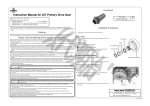
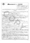
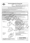
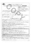
Kit Instruction Manual
Item No.: 01−03−0115
CO
Model types with applicable cylinder heads and frame Nos
KSR110 :KL110A-000001 ∼
KLX110 :LX110A-000001∼
:LX110A-A08133∼
KLX110L:LX110D-A72046∼
・Thank you for purchasing one of our TAKEGAWA's products. Please strictly follow the following instructions to install and use the products.
・Before fitting the products, please be sure to check the contents of the kit. If you have any questions about the products, please contact your local TAKEGAWA dealer.
∼ Features ∼
○ This is a Super head for exclusive for use with KSR110 / KLX110. We have enlarged the valve top diameters both for intake and exhaust. And we have
designed the valve angle of nip and port shape exclusively for these model types. We have incorporated roller bearings into the slipper of a valve rocker
arm. The increased weight caused by incorporation of bearings is offset by adoption of an aluminium-forged rocker arm which consequently brings about
power increase at a high rotary area as a result of the synergy effect.
Please read the following before the installation.
◎ Please note that, in some cases, the illustrations and photos may vary from the actual hardware.
◎ We do not take any responsibility for any accident or damage whatsoever arising from the use of the products not in conformity with the instructions in
the manual.
◎This kit is designed for exclusive use in the above-mentioned model types with specified applicable frame Nos only, and in the vehicles equipped with the
special bore-up exclusively for this kit. Please take note that this kit cannot be mounted on other types of motorcycles or compatible with other bore-up
than the special one for this kit.
◎ Installation of this product requires removal and reinstallation of an engine, and disassembly of a clutch. Please prepare genuine service manual for the
above-mentioned applicable models, and work with enough care following instructions in the service manual. Besides, this instruction manual, as well as
service manual, is prepared for those who have acquired basic skill and knowledge in tuning. We recommend those who are technically inexperienced
or without right tools to ask a technically-trustworthy specialist shop to do the work for you.
◎ We shall be held free from any kind of warranty whatsoever of products other than this product if the glitch takes place on the other products than
this one after the installation and use of this product.
◎ You are kindly requested not to contact us about the combination of our products with other manufacturers’
◎ A serial number is stamped on the cylinder head. You may be requested to inform us of the number when ordering parts. ◎ Some of bolts and nuts will be reused. However, be sure not to use the worn-down or severely-damaged ones, which please do replace with new ones.
◎ Do not use liquid seals, which may oppilate oil's passage; it may break the engine in the worst case.
◎ Be sure to always use premium unleaded petrol. And make sure to check what kind of gasoline is remaining in the fuel tank. Whenever regular gasoline
is left in the fuel tank, always replace it with high-octane gasoline.
◎ Determine the heat value of a spark plug depending on how much it is burnt.
◎Please be informed that what we can safely say is that the ignition system of this kit is compatible with ours and stock ignition systems, because no data
is available with us on the compatibility with other ignition systems. So never use this kit together with any other ignition system to avoid technical troubles.
◎ Install an oil cooler when necessary.
◎ Engine oil must be API SF or higher class, such as SAE 10W-40 / 15W-50, which are our recommendations.
◎ Change the sprocket with the one to meet the vehicle’s power and specifications.
◎In case you have purchased this kit for use just as a cylinder head kit, you cannot use this kit in this way. If you have not purchased ”special engine parts
compatible with this kit”, please purchase separately the special parts referring to the”Reference data on bore-up kit.”
◎ This kit is only compatible with those engine parts recommended by us. So, please replace the parts not recommended by us with those of our recommendations.
◎This product is designed for exclusive use on the closed course, but not for use on a public road. And always try to drive your motorcycle at a legal speed,
abiding by the laws.
PY
Quick starting and sudden acceleration
Idling, sudden acceleration, and sudden engine braking will put a heavy load on the engine, which may result in crank shaft damage and engine
breakage in the worst case.
◎ Please be informed that, mainly because of improvement in performance, design changes, and cost increase, the product specifications and prices
are subject to change without prior notice.
◎ This instruction manual should be retained for future reference.
The following show the envisioned possibility of injuries to human bodies and property damage as a result of disregarding the
Caution following cautions.
・This product is designed for exclusive use on the closed course, but not for use on a public road. And always try to drive your motorcycle at a legal speed, abiding by the laws.
・Do the work only when the engine and exhaust system are cold at below 35 degrees C to avoid burns.
・Prepare appropriate tools and work properly to avoid the breakage of parts or injuries.
・As some products and frames have sharp edges or protruding portions, work with your hands protected to avoid injuries.
・Always use new gasket and seals. (Worn or damaged parts may cause engine troubles.)
- A’1 -
Nov./04/’
10
The following show the envisioned possibility of human death or serious injuries to human bodies as a result of disregarding the following
Warning cautions.
・Those who are technically unskilled or inexperienced are required not to do the work. (Improper installation due to unskilled technique or lack of knowledge could lead to parts breakage and consequently to accidents.)
・Before doing work, place the motorcycle on level ground to stabilize the position of your motorcycle for safety's sake.
(Otherwise, your motorcycle could overturn and injure you while you are working.)
・Always start the engine in a well-ventilated place, and do not turn the engine on in an airtight place. (Otherwise, you will suffer from carbon monoxide poisoning.)
・As gasoline is highly flammable, never place it close to fire. Make sure that nothing flammable is near the gasoline. (It may cause a fire.)
・Always use a torque wrench to screw bolts and nuts tight and securely to the specified torque. (Improper torque could cause these parts to get
damaged or fall off.)
・Never use the parts unspecified by us. (This may lead to parts breakage and consequent accidents.)
・If you find damaged parts when checking and performing maintenance of your motorcycle, do replace them with new ones.
(The continued use of these damaged parts could lead to parts breakage and accidents.)
・When you notice something abnormal with your motorcycle while riding down a road, stop riding immediately and park your motorcyle in a safe place. (Otherwise, the abnormality could lead to accidents.)
・Before riding, always check every section for slack in parts like screws. If you find slack ones, screw them securely up to the specified torque.
(Or improper torque may cause parts to come off, leading to accidents.)
・Check or carry out maintenance of parts correctly according to the procedures in the instruction manual or a service manual. (Improper checking or
maintenance could lead to accidents.)
・Fuel must be high-octane gasoline. (Otherwise, troubles such as engine knocking may cause accidents.)
CO
●Cautions before riding:
●Titanium valve spring retainer (optional)
① About fuel:
Whenever regular gasoline is remaining in the fuel tank, always replace it
with high-octane gasoline.
② Change of a sprocket:
◇ This Super Head has optional titanium valve spring retainers.
Titanium retainers are about 30% lighter than steel retainers.
The surface is treated with a special coating of which hardness is HV1000
above for added shock-resistance and wear-resistance.
PY
◇ The installation of this product will increase the power of your vehicle.
So use of a normal sprocket will result in severe wears of parts because
of too low gear, not only adversely affecting the engine life, but also breaking the engine in the worst case. Please replace the sprocket with
the high-geared one.
Item No.01-12-084 (2 pcs)
This kit cannot function on its own. Referring to the
attached sheet, please purchase a bore-up kit for
exclusive use in this kit. This does not apply to the
case where you have purchased a full kit.)
● A serial number is stamped on the cylinder head just for the sake of administration. You may be requested to inform us of the number when ● Others:
Oil cooler:
◇ The installation of this product increases the heat release value of the engine, set off by the increase in power. For a long-time high-load running,
we recommend you to install an oil cooler kit which keeps oil at appropriate
temperatures and prevents such troubles as oil film shortage at high
temperatures.
Carburetor manifold:
◇ If you use a manifold, compatible with S-Stage, with a port diameter of φ
22.5 on the side of an inlet pipe, there will be a bump because of the difference in diameter between the cylinder head and the manifold.
Enlarging the manifold's port diameter on the manifold side will provide you
with smoother output characteristics.
.5
7
φ2
KL1-00000
2
2
φ
☆ Make a note of the number stamped on the left side of the cylinder head.
Head No.: KL1-00001
Example of ordering → Super Head Kit, repair part
Head No.: KL1-00001 → Intake valve
Qty:1
2.3
φ 22.5 →φ 27
ordering repair parts. In case you are not able to order parts because you
do not have the repair parts numbers or for other reasons, please place an
order in the following way.
●Upper limt of revolutions:
Head No. stamped here
◇ Upper limt of revolutions varies depending on the installed cam shafts, etc. Referring to the camshaft comparison graph on page A3, install a
revolution counter to make sure that you drive the engine at revolutions below the upper limit.
◇Take note that idling and sudden acceleration in the 1st and the 2nd gears
particularly tend to exceed the upper limit of revolutions. Over revolutions
will result in nonsmooth revolutions of the engine, not only adversely affecting the engine life, but also breaking the engine in the worst case.
KL1-00***
● For those who have purchased a cylinder head as a single item, some products are available from us to meet engine displacement and other requirements. Please study to install the products, referring to “Reference
data on bore & stroke-up kit.” For more details about the products or queries, please contact your dealer.
- A’2 -
Nov./04/’
10
●Engine parts of our recommendation:
※This kit is compatible only with the engine parts of our recommendations. Therefore, please replace those parts not recommended by us with those parts
of our recommendations.
Recommended Part
Heavy-duty clutch spring kit
Clutch
Ignition system Stock C.D.I.
KSR110
Keihin PE28 carburetor kit
KLX110
Carburetor
KSR110
Mikuni VM26 carburetor kit
KLX110
02-01-0296
03-05-3272
03-05-3292
03-05-3273
03-05-3293
CO
● About cam shaft
○ This kit does NOT include a camshaft.You need to have a camshaft for this Cylinder Head works.
There are some available types of camshafts in order to match your riding purpose or displacements.
Please select referring to the chart or the graph.
○ Optional camshafts
○ Several types of camshafts are available. Please choose a camshaft to suit your riding purpose and displacements.
Camshafts Number
S-15D
S-20D
S-25D
S-35D
KLX110/KSR110
Camshaft w/auto-decompression
01-08-0119
01-08-0120
01-08-0121
01-08-0122
Camshafts Number
S-15
S-20
S-25
S-35
KLX110/KSR110
Camshaft w/auto-decompression
01-08-0015K
01-08-0020K
01-08-0025K
01-08-0030K
Camshafts Number
S-15D
S-20D
S-25D
S-35D
KLX110L
Camshaft w/auto-decompression
01-08-0132
01-08-0133
01-08-0134
01-08-0135
○ Each Bore up kit includes a camshaft. Optional camshafts are available other than the supplied camshaft.
The included camshafts in the Bore up Kits
Model
KLX110
KLX110
KSR110
KLX110L
125cc / 138cc
178cc
125cc / 138cc / 178cc
125cc / 138cc / 178cc
S-15D
S-20D
S-20D
S-20D
Part No.
01-08-0119
01-08-0120
01-08-0120
01-08-0133
PY
○ About Camshafts Number
The bigger the numbers of XX / YY are, the wider the durations are. With these camshafts, the output power will produce more to high rpm range. While,
the smaller the numbers are, the narrower the durations are. With these camshafts, the output power will produce more to low-to-mid rpm range. We supply
the suitable camshaft depending on the displacements.
When choosing the optional camshafts, please choose the camshaft referring to the camshaft data chart to suit your riding purpose.
Also, the engine output will vary significantly depending on the using exhaust system, length of inlet pipe, carburetor diameter, compression ratio, ignition
system, ignition timing, fuel or natural phenomenons such as ambient temperature or atmospheric pressure.
☆Lists of camshaft comparison data
NB) As these are the data measured on a Dyno Jet, the data differ from the actual driving. Please see them just as a reference.
The engine power varies significantly depending on the temperatures.
KSR138cc SuperHead+R KEIHIN PE28 Racing Muffler
KSR178cc SuperHead+R SCUT MIKUNI VM26
22
20
35 cam
20
18
25 cam
20 cam
18
16
SAE Power(PS)
15 cam
12
10
8
6
4
SAE Power(PS)
16
14
14
12
10
8
6
4
2
2
RPM(x1000)
0
3
4
5
6
7
8
15 cam
9
10
11
12
RPM(x1000)
0
3
13
4
25 cam
5
6
7
8
35 cam
KSR138cc SuperHead+R KEIHIN PE28 Racing Muffler
9
11
10
20 cam
KSR178cc SuperHead+R SCUT MIKUNI VM26
22
20
25 cam
20 cam
18
20
18
16
15 cam
35 cam
16
SAE Power(PS)
SAE Power(PS)
14
12
10
8
6
14
12
10
8
6
4
4
2
2
RPM(x1000)
0
3
4
5
6
20 cam
7
8
9
10
11
12
0
13
35 cam
RPM(x1000)
3
4
5
25 cam
- A’3 -
6
7
8
9
10
11
15 cam
Nov./04/’
10
∼ Kit Contents ∼
4
H
1
G
F
E
CO
D
C
B
2
A
2
C
D
E
F
G
H
PY
I
3
5
※ Please order repair parts with the Repair Part Item No.
Without the repair part item No., we may not be able to provide the correct parts.
Some parts are only available as a set. Please order them with the set number.
No.
1
2
3
4
5
Part Name
Cylinder head COMP.
Rocker arm COMP.
Cam stopper plate
Manifold gasket
Exhaust pipe gasket
Alumi Special (5 g)
No.
A
B
C
D
E
F
G
H
I
Part Name
Intake valve
Exhaust valve
Valve spring outer seat
Valve stem seal
Valve spring outer
Valve spring inner
Valve spring retainer
Valve cotter
Stud bolt
Qty
1
2
1
1
1
1
Repair Part No.
06120-KL1-T00
14431-SPH-T01
12211-KL1-T00
00-03-0007
00-01-0035
00-01-0001
In packs of
1
1
1
2
2
1
Qty
1
1
2
2
2
2
2
4
2
Repair Part No.
14711-KL1-T01-F
14721-KL1-T01-F
00-01-0002
00-01-0015
In packs of
1
1
2
2
2
2
2
4
2
01-12-0106 (SET)
00-01-0078
00-01-0018
00-01-0136
Over-sized valve guide for repair In packs of
00-01-0006 Valve guide O / S
1
Co.,Ltd.
3-5-16 Nishikiorihigashi Tondabayashi Osaka Japan
- A’4 -
TEL : 81-721-25-1357 FAX : 81-721-24-5059 URL : http://www.takegawa.co.jp
Nov./04/’
10
∼ Cylinder Head Installation Procedures ∼
○Remove a rocker arm shaft of the original cylinder head, and an
adjusting bolt / nut on the rocker
arm.
○ Fix the special cam shaft.
Apply engine oil to the bearing.
CO
○ Pull out the rocker arm shaft on the
intake side. And Move the rocker arm
○ Apply engine oil to the removed
adjusting bolt, which please
attach to the rocker arm of the kit.
OIL
○ Attach the rocker arm to the
super head. Put the rocker arm for the intake into the tappet hole
on the exhaust side of the super
head. And fix the rocker arm shaft
after applying molybdenum
solution to it.
And attach the rocker arm for the
exhaust by the same token.
on the intake side out of place
toward the tappet hole and attach a
special cam shaft to the cylinder head. And attach the rocker arm on
the intake side and rocker arm shaft.
At this point, set the position of the
camshaft tops for both intake and
exhaust so they face toward the
combustion chamber.
○ Fix a cam stopper plate of the kit to
the super head with two pan screws which have just been
unfastened from the original
○ Slightly apply Alumi Special, the
heat-resistant lubricating agent, to
threaded portions of the cylinder
head stud and head bolt, and cylinder head. Fix the stopper plate,
aligning both ends of the cam
stopper with a rocker arm shaft notch. And tighten it to the specified
torque.
Caution: Never fail to follow the specified torque.
T=8 N・m (0.8 kgf・m)
loosely tighten the head nut and
head bolt.
Head
nut
Head
nut
Head
nut
Head
nut
Head
bolt
Align the
Align the
mounting point. mounting point. ○ Tighten 4 head nuts and 2 head
bolts diagonally in a few steps to
the specified torque in the order
indicated in the figure below.
Caution: Never fail to observe the
specified torque.
For head bolt:
T=12 N・m (1.2 kgf・m)
For head nut:
T=22N・m (2.2 kgf・m)
PY
(∴As the bearings of the cam shaft
and rocker arm interfere with
each other, it is necessary to
move the rocker arm out of
position and attach the cam shaft.)
Move out of
position
Head
bolt
○ Set the dowel pin in the dowel pin
hole on the cylinder.
Dowel pin
②
④
③
①
⑥
⑤
○ Degrease well the upper surface
of the cylinder.
○ Reinstall the oil pipe in the same
way as it was installed, and tighten the banjo bolt to the specifed torque.
Caution: Never fail to observe the
○Attach a cylinder head gasket of the
kit to the cylinder.
specified torque.
T=15N・m (1.5 kgf・m)
NEW
○ From the original cylinder head,
detach two pan screws which are
holding a cam stopper.
○ Setting the piston to be at top dead
center, attach the cylinder head.
○ Fix the bolt which is to clamp the
oil pipe, and tighten it.
Caution: Never fail to observe the
specified torque.
T=5.2N・m (0.53kgf・m)
- B’1 -
Nov./04/’
10
● KSR110
KLX110
Install the camshaft without
auto-decompression.
○ Attach the cam chain to the cam
sprocket. When the “T” mark on
the flywheel is aligned with the alignment mark on the crankcase,
align the “T” mark on the cam sprocket with the alignment mark
on the cylinder head.
○ Put the 6x20 cap screw into the collar and put them into the weight.
Weight
CO
Alignment mark
“T” mark
Collar
Cap screw
○ Put the 6x20 cap screw into the upper hole on the cam sprocket, and
tighten the screw to the specified
torque.
NOTE: Be sure to follow the
specified torque. ○ Fasten the cam sprocket to the
cam shaft with two screws to the
specified torque.
Caution: Never fail to observe the
specified torque.
T=12 N・m (1.2 kgf・m)
○ Put a socket cap screw 6 x 20 into
the decomp collar 2, and put them in
the weight.
Weight
groove.
NOTE : Do not expand the snap ring more than necessary.
WARNING : Always use a NEW
snap ring, and be sure
NOT to reuse it.
tensioner with two screws, and
tighten them to the specified torque.
Caution: Never fail to observe the
specified torque.
T=12 N・m (1.2 kgf・m)
PY
● KLX110L
Install the camshaft with
auto-decompression.
Decomp collar 2
○While aligning the “T” mark of
flywheel and the notch of
crankcase, install the cam chain on
the cam sprocket included in the Camshaft Kit. (NOTE: CANNOT use
stock cam sprocket.)
Socket cap screw
○ Install successively with the decomp guide, weight, and decomp
collar 2 referring to the drawing, and
tighten them to the specified torque.
NOTE: Be sure to follow the
specified torque.
Cap screw 6 x 20
:Torque: 12N・m (1.2 kgf・m)
Cam sprocket
Decomp guide
Weight
Decomp collar 2
Alignment mark
Cap screw
6 x 20
● KSR110
KLX110
Install the camshaft with auto-decompression.
○ Attach the snap ring in the shaft
○ Check that a push rod of a cam
shaft chain tensioner is locked.
○Install the cam shaft chain Torque: 12N・m (1.2 kgf・m)
Alignment mark
“T” mark
○ Install the decomp guide in such a
way that the thicker side of the screw mounting is up (to IN), the
thinner side is down (to EX), and attach a cap screw 6 x 12 to the down side (the EX side).
Then tighten them to the specified
torque.
NOTE: Be sure to follow the
specified torque.
Cap screw 6 x 12
:Torque: 8N・m (0.8 kgf・m)
※Make sure that the direction of decomp guide must be correct.
○Remove a cap bolt on the cam shaft chain tensioner, and rotate
a little bit a stopper on the cam shaft chain tensioner
counterclockwise to unlock the push rod.
“T” mark
Alignment mark
○ Fasten and tighten the 6x12 cap
screw on the exhaust side of the
cam sprocket to the specified torque.
NOTE: Be sure to follow the
specified torque.
Torque: 12 N・m (1.2 kgf・m)
Cap screw 6 x 12
○ Pass a 6mm snap ring and a plate
into the supplied 3x28 thumb screw
and attach them to the tip of the shaft
that is included in the camshaft COMP. And pull them toward you.
○Install the cap bolt of the cam shaft
chain tensioner, and tighten it to
the specified torque.
Caution: Never fail to observe the
specified torque.
T=5.2 N・m (0.53 kgf・m)
Cap bolt
Thumb screw
- B’2 -
Nov./04/’
10
○Check that the “T” mark on the
○ Give the crank shaft two turns
○ Fix the carburetor following the kit
○ Attach a sprocket cover.
flywheel is aligned with the “T” mark on the cam sprocket.
counterclockwise to check if the valve clearance changes.
In case it changes, adjust the
clearance until it meets the
specification.
instruction manual.
○ Connect a crankcase breather hose.
Caution: Never fail to observe the
specified torque.
T=5.2 N・m (0.53 kgf・m)
○ Connect a connector on the
generator cover.
○ Fix an exhaust muffler referring
to its installation procedures.
○ Adjust the valve clearance with
an adjusting screw.
IN:0.05 ∼ 0.08 (When cold.)
EX:0.05 ∼ 0.08 (When cold.)
CO
○Apply engine oil slightly to an O-ring
on the cam shaft sprocket cover, and
fasten the sprocket cover to the
cylinder head with four screws to
the specified torque.
Caution: Never fail to follow the specified torque.
T=5.2 N・m (0.53 kgf・m)
●In case you install an
automatic decompression
cam shaft:
※ When adjusting the valve
clearance, leave the shaft,
supplied in the camshaft COMP.,
pulled toward you lest the
decompression device operate on
the exhaust side.
○Tighten the adjusting nut to the specified torque.
Caution: Never fail to observe the
specified torque.
T=8.8 N・m (0.9 kgf・m)
☆ Engine Starting ☆
○ Check that an ignition key and a
gas cock are turned off.
PY
○Apply engine oil slightly to an O-ring
on the inspection cap, and fix the inspection cap with two screws to
the specified torque.
Caution: Please never fail to follow
the specified torque.
T=5.2 N・m (0.53 kgf・m)
○ Unscrew the thumb screw.
specified torque.
T=5.2 N・m (0.53 kgf・m)
○ Degrease the mating surface of the
generator cover and the crankcase,
and attach two dowel pins and a new gasket.
○ Wipe out thoroughly the dirt and
dust on the engine.
○ Turn on the gasoline cock and
ignition key to start the engine.
○ See if there is anything wrong
including strange sounds.
○ If nothing wrong is detected, do
the running-in of about 30 to 50 ○ Inject engine oil in the specified amounts.
3
2
km, and then recheck the valve clearance.
Caution: Do the valve clearance
rechecking only when the engine and muffler are cold.
○ Do the running-in again of 100 to
1
6
resistant lubricating agent, to the
threaded portion of the plug, and
fasten the plug tightly.
Caution: Never fail to observe the
specified torque.
○ Attach the plug cap to the spark
plug.
Warning: Be sure to start the
engine in a well ventilated place.
4
5
○ Continue kicking the starter for a
while to circulate the engine oil throughout the engine.
○ Fix a spark plug.
Slightly apply Alumi Special, heat-
○ Fix a shift pedal.
Caution: Please follow the
○ Fix the generator cover with nine
bolts to the specified torque in a few
steps in the numerical order.
Caution: Never fail to observe the specified torque.
T=5.2 N・m (0.53 kgf・m)
●In case you install an
automatic decompression
cam shaft:
○ Attach a drive sprocket and a drive
chain.
9
150 km.
8
○ After the running-in, see if there
7
○ Referring to the service manual, mount the engine onto the frame.
Caution: Please follow the
instructions in the service
manual.
- B’3 -
is nothing wrong like strange sounds or blow-by gas.
If something wrong is found, disassemble the engine again to
check every part of it.
Warning: Never reuse the
unusable parts.
Nov./04/’
10
01―03―0115
camshaft
camshaft
camshaft
camshaft
01-08-0015K
01-08-0020K
01-08-0025K
01-08-0035K
camshaft
camshaft
camshaft
camshaft
01-08-0119
01-08-0120
01-08-0121
01-08-0122
124cc
138cc
178cc
01―04―0104
124cc Cylinder Kit
01―04―0105
138cc Cylinder Kit
01―04―0114
178cc SCUT Cylinder Kit
01―02―0101
124cc φ56
01―02―0102
138cc φ59
178cc φ67
00―01―0058
KSR110,KLX110ボアアップ参照表(124cc、138cc、178cc)
KSR110,KLX110 Reference data on bore-up kit (124cc,138cc,178cc)
S-15
S-20
S-25
S-35
STD
カムを選択
Select a cam
PY
Select a cylinder
If you have purchased a cylinder head kit only (Item No. 01-03-0115), please study to install these special parts referring to this reference data.
☆01―03―0115シリンダーヘッドキットのみで購入された場合、この参照表にて専用パーツを検討して下さい。
S-15D
S-20D
S-25D
S-35D
AUTO DECOMP
シリンダー選択
CO
Aug./30/’
10
01―03―0115
S-15D
S-20D
S-25D
S-35D
camshaft
camshaft
camshaft
camshaft
01-08-0132
01-08-0133
01-08-0134
01-08-0135
124cc
178cc
138cc
Select a cylinder
01―04―0104
124cc Cylinder Kit
01―04―0105
138cc Cylinder Kit
01―04―0114
178cc SCUT Cylinder Kit
01―02―0101
124cc φ56
01―02―0102
138cc φ59
178cc φ67
If you have purchased a cylinder head kit only (Item No. 01-03-0115), please study to install these special parts referring to this reference data.
☆01―03―0115シリンダーヘッドキットのみで購入された場合、この参照表にて専用パーツを検討して下さい。
00―01―0058
KLX110Lボアアップ参照表(124cc、138cc、178cc)
KLX110L Reference data on bore-up kit (124cc,138cc,178cc)
カムを選択
PY
AUTO DECOMP
Select a cam
シリンダー選択
CO
Aug./30/’
10