1
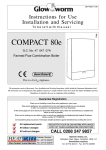
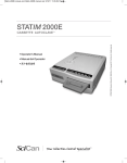
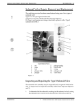
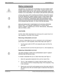
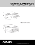
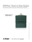
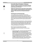
Cover Removal, Servicing and Replacement
96-104266 Rev. 1.0
Cover Removal and Replacement
Removing the Cover:
To remove a STATIM / STATIM 1000 / 2000 cover, follow these steps (see Figure
1):
1.
Inspect the cover (1) to ensure that it has not been damaged in transit.
Position the unit on the bench so the front leveller feet are securely on
the work surface and the front cover extends past the work surface edge.
2.
Check that the LCD (2) and keypad (3) function. This requires that the
unit be powered ON. CHECK FOR SYMPTOMS OF THE FAILURE TO
ENSURE THAT NO FURTHER DAMAGE OCCURS.
3.
Turn the power OFF and unplug the power cord (4) from the wall outlet
and remove the cassette from the unit.
4.
Remove the reservoir cap (5) from the top of the unit.
5.
Remove seven screws from the cover; first remove two on each side (6)
and then three with lockwashers (7) at the rear of the unit, using a #2
Phillips screwdriver.
STATIM 2000 units are manufactured with a bacteria-retentive air filter (9)
attached to the rear of the unit. If the bacteria-retentive air filter is present,
follow the steps found in Required Information, Tools and Routine Maintenance, Removing the Bacteria-Retentive Filter to disconnect the tubing
before attempting to remove the cover.
CONFIDENTIAL
6.
Slowly, lift the rear portion of the cover upwards. When the cover is
clear of the internal components, carefully slide the entire cover forward
approximately 5 cm / 2 inches to clear the front of the armature and
unsupported Controller Board (8). Slowly pivot the cover as shown in
Figure 1 and place it immediately next to the unit. The keypad and LCD
are still accessible and the internal components are exposed.
THE CONTROLLER BOARD IS UNSUPPORTED AT THE FRONT OF
THE UNIT. THE KEYPAD AND LCD CABLES ARE STILL ATTACHED
TO THE CONTROLLER BOARD.
7.
Observe the orientation of the ribbon cable connections: disconnect the
LCD connector from Controller Board header P3 (P2 for Type A & B
boards), and the keypad connector from Controller Board header P4 (P3
for Type A & B boards).
8.
Replace the reservoir cap onto the top of the reservoir.
1
STATIM / STATIM 1000 / 2000 Cassette Autoclave Service Manual
96-104266 Rev. 1.0
Cover Removal, Servicing and Replacement
4
1
7
2
3
1.
2.
3.
4.
5.
cover
LCD
keypad
power cord
reservoir cap (not shown)
6.
7.
screws for side of unit
screws with lockwashers
for rear of unit
Controller Board
bacteria-retentive air filter (not shown)
filter bracket (not shown)
6
8.
9.
10.
8
Figure 1
STATIM / STATIM 1000 / 2000 Cassette Autoclave Service Manual
2
CONFIDENTIAL
Cover Removal, Servicing and Replacement
96-104266 Rev. 1.0
Reinstalling the Cover
To reinstall the cover follow these steps (see Figure 1).
1.
Inspect the armature gasket located on the inside front portion of the
cover. If it is damaged or fails to adhere to the surface of the cover, it
must be replaced. See Replacing the Armature Gasket.
2.
Remove the reservoir cap (5) from the top of the reservoir.
3.
Rest the cover (1) beside the left side of the unit. Reconnect the keypad
connector to Controller Board header P4 (P3 for Type A & B boards)
and the LCD connector to Controller Board header P3 (P2 for Type A
& B boards).
4.
Reconnect the power cord (4) and power the unit ON to check that the
LCD and keypad are functioning. If the amber LED on the front cover is
flashing, or the solenoid valve is activated repeatedly, the LCD connector is incorrectly installed. Check that the keypad connector is properly plugged onto the header. Select a cycle and wait for the proper
display messages. After checking, turn the power switch OFF and
unplug the power cord.
5.
Carefully lift the cover from the work surface. While rotating the cover
slide it forward until the fascia clears the Controller Board and the front
of the armature.
6.
Tilt the front of the cover down and the rear of the cover upwards. Carefully reposition the front portion of the cover back over the front of the
Controller Board (8) and armature. Ensure that the LEDs at the front left
hand corner of the unit fit into the clearance holes in the cover. BE
CAREFUL NOT TO PINCH THE RIBBON CABLES.
7.
When the front of the cover is in place, lower the rear portion of the
cover, and gently push backwards. Carefully realign the screw holes and
reinstall three screws with lockwashers (7) across the rear of the unit.
If the unit being serviced has a bacteria-retentive air filter (9), reconnect the
tubing as described in Required Information, Tools and Routine Maintenance.
8.
Reinstall the four remaining screws (6), two on each side. Press firmly
on the top of the cover to compress the gaskets and partially reinstall
the screws as the holes align. When in place, tighten all the screws. Do
not over tighten the screws.
9.
Fill the reservoir with steam process distilled water and place the reservoir cap (5) back onto the reservoir.
10. Reconnect the power cord (4). Select a cycle to ensure that the keypad
and LCD function, then press the STOP key.
CONFIDENTIAL
3
STATIM / STATIM 1000 / 2000 Cassette Autoclave Service Manual
96-104266 Rev. 1.0
Cover Removal, Servicing and Replacement
Replacing the Armature Gasket
To replace the armature gasket follow these steps (see Figure 2).
1.
Remove all traces of the gasket and gasket adhesive from inside the
fascia (1). The fascia is made of a thermoplastic. DO NOT USE
AROMATIC SOLVENTS ON THE FASCIA. This will damage the
fascia. To prepare for installation of the new gasket (2), roughen the
inside surface of the fascia where the gasket sits, using a fine grit
sand paper.
2.
Leave the carrier paper on the adhesive side of the gasket and perform a trial fit. Note that the widest part of the gasket fits at the bottom of the opening and that the gasket does not protrude into the
opening.
3.
Remove the carrier paper from the adhesive side of the gasket.
Carefully install the gasket making sure it is seated firmly in place.
4
2
1
3
STATIM / STATIM 1000 Cover Assembly
1.
2.
3.
4.
fascia
armature gasket
cover
plastite screw
Figure 2
STATIM / STATIM 1000 / 2000 Cassette Autoclave Service Manual
4
CONFIDENTIAL
Cover Removal, Servicing and Replacement
96-104266 Rev. 1.0
Removing and Replacing the Fascia
!
THE FASCIA CONTAINS THE LCD AND MEMBRANE KEYPAD.
STATIM / STATIM 1000 / 2000 UNITS CONTAIN ELECTRONIC COMPO-
NENTS WHICH MAY BE DAMAGED OR DESTROYED BY ELECTROSTATIC DISCHARGE (ESD). OBSERVE APPROPRIATE SAFEGUARDS
WHEN SERVICING. ALWAYS TRANSPORT ELECTRONIC COMPONENTS
AND ASSEMBLES IN STATIC-PROTECTED PACKAGING.
STATIM / STATIM 1000 units have been manufactured using a straight profile
fascia with a continuous keypad and LCD cover. STATIM 2000 units have
been manufactured with a curved fascia which utilizes a separate keypad and
LCD cover.
Removing the Fascia
To remove the fascia (1), follow these steps (see Figure 2):
1.
The fascia is attached to the cover (3) using five Plastite™ screws (4).
Remove and retain the screws.
2.
A bead of silicone was used to provide a water-tight seal between the
facsia and cover during manufacturing. Remove the fascia and any
silicone residue remaining on the cover.
3.
The fascia is made of recyclable plastic. If the fascia is to be discarded
please recycle wherever possible.
Replacing the Fascia
To replace the fascia (1), follow these steps (see Figure 2):
CONFIDENTIAL
1.
Apply a bead of silicone between the facsia and cover (3) to provide a
water-tight seal.
2.
Install the new fascia using the 5 screws (4) retained from the
disassembly procedure.
3.
Reinstall the cover. See, STATIM / STATIM 1000/2000 Cover Removal
and Replacement. Verify that the keypad and LCD function correctly.
5
STATIM / STATIM 1000 / 2000 Cassette Autoclave Service Manual
96-104266 Rev. 1.0
Cover Removal, Servicing and Replacement
LCD Removal and Replacement
STATIM / STATIM 1000 / 2000 UNITS CONTAIN ELECTRONIC COMPO-
NENTS WHICH MAY BE DAMAGED OR DESTROYED BY ELECTROSTATIC DISCHARGE (ESD). OBSERVE APPROPRIATE SAFEGUARDS
WHEN SERVICING. ALWAYS TRANSPORT ELECTRONIC COMPONENTS
AND ASSEMBLES IN STATIC-PROTECTED PACKAGING.
8
P3
9
1
P4
3
2
6
4
7
5
STATIM / STATIM 1000 unit with Type C PCB shown
1.
2.
3.
LCD assembly
fascia
membrane keypad/
LCD overlay
4.
countersink screws
(under overlay)
captive fasteners
5.
1
6.
7.
8.
9.
keypad cable
LCD cable
Controller Board
DISP potentiometer
Figure 3
STATIM / STATIM 1000 / 2000 Cassette Autoclave Service Manual
6
CONFIDENTIAL
Cover Removal, Servicing and Replacement
96-104266 Rev. 1.0
Removing the LCD
To remove the LCD (1) from the fascia (2), follow these steps (see Figure 3):
1.
Carefully remove the membrane keypad/LCD overlay (3) from the
fascia. See Membrane Keypad Removal and Replacement. Removing the overlay may damage the keypad. Have a replacement available in the event damage occurs.
2.
Using a #1 Phillips screw driver remove and retain the four countersunk
screws (4) securing the LCD to the fascia. Each screw is held by a captive
fastener (5) which is integral to the LCD assembly. In earlier units each
screw is held with a nut and washer.
3.
The keypad cable (6) and the LCD cable (7) may be secured together with double sided adhesive tape. Carefully separate the harnesses and remove the LCD.
Replacing the LCD
To replace the LCD (1), follow these steps (see Figure 3):
CONFIDENTIAL
1.
Align the captive fasteners (5) on the LCD with the four clearance
holes in the fascia (2) and reinstall the LCD using the four countersunk screws (4) retained from disassembly. The LCD cable (7) and
the keypad cable (6) are on the left side of the cover.
DO NOT PRESS DOWN IN THE MIDDLE OF THE LCD ASSEMBLY.
APPLY PRESSURE IN THE AREAS IMMEDIATELY ADJACENT THE
MOUNTING HOLES ONLY.
2.
Carefully reinstall the membrane keyboard/LCD overlay (3) on the
fascia. See Membrane Keypad Removal and Replacement.
3.
Secure the cables together using double sided adhesive tape.
4.
Connect the keypad connector to Controller Board (8) P4 (P3 for Type A
& B boards).
5.
Connect the LCD connector to Controller Board P3 (P2 for Type A & B
boards).
6.
Power the unit ON. If the LCD fails to display the “select a cycle” message, the connector is improperly installed or the LCD intensity pot is
not adjusted correctly. If the amber LED on the front cover is flashing or
the solenoid valve is activating repeatedly, the LCD connector is incorrectly installed.
7.
If the LCD intensity or contrast is not suitable, adjust the potentiometer
labelled DISP (9), on the Controller Board.
8.
Reinstall the cover. See, STATIM / STATIM 1000 / 2000 Cover Removal
and Replacement.
7
STATIM / STATIM 1000 / 2000 Cassette Autoclave Service Manual
96-104266 Rev. 1.0
Cover Removal, Servicing and Replacement
Membrane Keypad Removal and Replacement
STATIM / STATIM 1000 / 2000 UNITS CONTAIN ELECTRONIC COMPO-
NENTS WHICH MAY BE DAMAGED OR DESTROYED BY ELECTROSTATIC DISCHARGE (ESD). OBSERVE APPROPRIATE SAFEGUARDS
WHEN SERVICING. ALWAYS TRANSPORT ELECTRONIC COMPONENTS
AND ASSEMBLES IN STATIC-PROTECTED PACKAGING.
DO NOT OVER-BEND OR TWIST THE MEMBRANE KEYPAD.
Removing the Membrane Keypad
To remove the membrane keypad (1), follow these steps (see Figure 4):
1.
The keypad flexible cable and the LCD ribbon cable may be secured
together with double sided adhesive tape. Carefully separate the cables.
2.
Using a sturdy sharp instrument, carefully lift one corner of the membrane keypad and CAREFULLY peel the membrane keypad away from
the fascia (5). EXERCISE CAUTION, there may be adhesive on the
edges of the LCD. Pass the connector through the slot (6) in the fascia.
3.
Carefully remove any residual adhesive or membrane from the recessed keypad area of the fascia using a sharp blade. DO NOT USE
AROMATIC SOLVENTS TO REMOVE ADHESIVE FROM THE THE
FASCIA OR THE MEMBRANE KEYPAD.
Replacing the Membrane Keypad
To replace the membrane keypad (1), follow these steps (see Figure 4):
1.
Connect the new keypad cable (4) connector to Controller Board (2) P4.
2.
Plug in the power cord and power the unit ON. To test each button on
the keypad, ensure that a cassette is not inserted into the armature.
Select a cycle and press the START button. The LCD will display
"INSERT CASSETTE". Repeat this step for each cycle to ensure the
keypad is functioning properly.
To test the STOP button select a cycle. The LCD message indicates
which cycle is selected. Press the STOP button. The LCD message will
change to "SELECT A CYCLE".
3.
Turn off and unplug the unit, and disconnect the keypad cable.
4.
The replacement membrane keypad has carrier paper on the back to
protect the adhesive. With the carrier paper in place, feed the keypad
cable (4) connector through the slot (6) in the fascia (5).
5.
Remove the carrier paper and align the bottom edge of the membrane
STATIM / STATIM 1000 / 2000 Cassette Autoclave Service Manual
8
CONFIDENTIAL
Cover Removal, Servicing and Replacement
96-104266 Rev. 1.0
keypad with the bottom edge of the recessed area on the fascia.
Carefully lower the membrane into place while continuing to draw the
keypad cable connector through the slot. With finger pressure only,
press the membrane into place, eliminating air pockets under the membrane.
6.
Secure the keypad cable and LCD cable together using double-sided
adhesive tape.
7.
Connect the keypad cable (4) connector to Controller Board (2) P4 (P3
for Type A & B boards).
8.
Connect the LCD cable (3) connector to Controller Board P3 (P3 for
Type A & B boards).
9.
Test the Membrane Keypad again by repeating steps 1 and 2.
10. Reinstall the cover. See Cover Removal , Servicing and Replacement.
2
P3
1
P4
5
3
1.
2.
3.
4.
5.
6.
membrane keypad
Controller Board
LCD cable
keypad cable
fascia
slot
4
6
STATIM / STATIM 1000 unit shown
Figure 4
CONFIDENTIAL
9
STATIM / STATIM 1000 / 2000 Cassette Autoclave Service Manual
96-104266 Rev. 1.0
STATIM / STATIM 1000 / 2000 Cassette Autoclave Service Manual
Cover Removal, Servicing and Replacement
10
CONFIDENTIAL
Cover Removal, Servicing and Replacement
96-104266 Rev. 1.0
Document Change Record
Document Number:
Title:
MANUAL-SERVICE-STATIM-COVER REMOV.
96-104266
REV.
DATE
1.0
97.11.24
CONFIDENTIAL
DESCRIPTION OF CHANGES
New.
ECO
97-069
11
STATIM / STATIM 1000 / 2000 Cassette Autoclave Service Manual