1
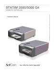
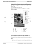
96-103936 Rev. 3.0
Controller Board Hardware / Software
Controller Board Hardware / Software
Hazardous voltages are accessible on the controller board when
the power is on. Disconnect the power cord before servicing the
power mains portion of the board.
STATIM units contain electronic circuitry which is static sensitive.
Always wear a static strap when working with or near printed wiring
boards. In addition, use static footstraps, grounding mats and
grounded. Work surfaces when servicing microprocessor
devices.
Identifying the Controller Board Type
There are different types of Controller Boards which may be
encountered while servicing STATIM units. The three main types of
Controller Board you will encounter are best described as; Type A, a
float switch connector only, Type B, a float switch and probe connector, a
printer connector and a W1 calibration connector header and Type C,
which is similar to Type B but has a PLCC-type microprocessor, (See
Figure1).
Determine the board type as described above. Note the manufactured
board part number and the voltage rating on the lower right-hand portion
of the component side of the board assembly. Refer to Table C at the
end of this document for upgrade / replacement, board part number /
revision / type references, and special parts compatibility information.
A new board will always work in an earlier unit.
Removing the Controller Board Assembly
To remove the Controller Board Assembly (1), follow these steps
(see Figure 1):
1.
Exercise extra caution. The thermocouple leads at the board
end are very fragile. Disconnect the steam generator
thermocouple wires (2) from Controller Board terminal positions
BOILER +Y and -R. Disconnect the chamber thermocouple wires
(4) from Controller Board terminal positions CHAMBER +Y and -R.
Disconnect the flag terminal (3) from the position marked BOILER.
Disconnect the flag terminal (5) from the position marked
CHAMBER. Retain the flag terminal screws. Leave the screws
with contact washers in the terminals. Carefully bend the leads so
they do not contact the Controller Board when it is removed.
1
CONFIDENTIAL
STATIM Cassette Autoclave Service Manual
Controller Board Hardware / Software
96-103936 Rev. 3.0
Close up of Type B, C
5
4
2
Controller Board Configurations
3
Type A - one 4 pin float switch connector
block labelled, FLOAT, CASSIN
1.
2.
3.
4.
5.
6.
Controller Board assembly
steam generator thermocouple wires
BOILER flag terminal
chamber thermocouple wires
CHAMBER flag terminal
microswitch leads
8
9
7
Type B - with printer connector, 6 pin
connector block labelled, FLOAT, PROBE,
CASSIN and W1 calibration connector header
2
6 pin connector block
W1
1
13
6
11
printer connector
12
10
11
7.
8.
9.
10.
11.
12.
13.
Type C - with PLCC-type microprocessor
water quality sensor leads
cable ties
armature
high voltage leads
screw with washer
chassis
printer cable
Figure 1
2
STATIM Cassette Autoclave Service Manual
CONFIDENTIAL
96-103936 Rev. 3.0
Controller Board Hardware / Software
Controller Board Hardware / Software
2.
Remove the microswitch leads (6) from Controller Board header
terminal positions labeled CASSIN.
3.
Remove the water quality sensor leads (7) (if present) from
Controller Board terminal positions labeled PROBE or the float
sensor leads (if present) from terminal positions labeled FLOAT.
4.
Remove Printer Cable (13) from connector P2 on board (if present).
5.
Disconnect all high voltage leads (10) from Controller Board block
terminal J1.
6.
Remove and retain the three screws with washers (11) that secure
the Controller Board assembly to the chassis (12).
Replacing the Controller Board Assembly
STATIM units contain electronic components that may be damaged or
destroyed by electrostatic discharge (ESD). Observe appropriate
safeguards when servicing. Always transport electronic components
and assembles in static-protected packaging.
To replace the Controller Board assembly, follow these steps
(see Figures 1 and 2):
1.
Visually inspect the replacement Controller Board assembly (fig 2,
item 1) to ensure that there is sufficient thermal compound (fig 2,
item 4) on the mounting bracket (fig 2, item 3) directly below the
triac (fig 2, item 2).
2.
Install the Controller Board assembly (1) using the three screws
with washers (11) retained from the disassembly.
3.
Connect the high voltage leads (10) from the power switch, steam
generator, pump, solenoid valve and compressor to Controller
Board J1. Each lead is numbered with a corresponding J1
designation. See Table B.
4.
Connect the microswitch leads (6) to Controller Board header
positions labeled CASSIN.
5.
Connect the water quality sensor leads (7) (if present) to Controller
Board positions labeled PROBE or the float sensor leads (if
present) to terminal positions labeled FLOAT.
3
CONFIDENTIAL
STATIM Cassette Autoclave Service Manual
Controller Board Hardware / Software
96-103936 Rev. 3.0
Controller Board Hardware / Software
6.
Connect the printer cable (13) to P2 on the control board.
7.
If installing a new thermocouple, carefully remove the protective
sleeve from the end of the uninsulated chamber thermocouple
leads. Pre-bend both leads to achieve the required shape.
Reconnect the flag terminal (5) on the chamber thermocouple (4)
to the threaded lug marked CHAMBER on the Controller Board.
Exercise caution, the thermocouple leads at the board end are
very fragile.
One lead is colour coded:
the unmarked lead is positive, +Y.
the red lead is negative, -R.
Connect the unmarked lead to the terminal marked +Y on the
Controller Board. Connect the red lead to the terminal marked -R
on the Controller Board. Make sure there is extra lead length so that
the wires do not break as the screw is tightened. Ensure the wires
are seated securely behind the respective washers (see Figure 2
detail).
The two leads must not touch one another or any other
component.
Reconnect the flag terminal (3) on the boiler / steam generator
thermocouple (2) to the threaded lug marked BOILER on the
Controller Board. Exercise extra caution, the thermocouple
leads at the board end are very fragile.
One lead is colour coded:
the unmarked lead is positive, +Y.
the red lead is negative, -R.
Connect the unmarked lead to the terminal marked +Y on the
Controller Board. Connect the red lead to the terminal marked -R
on the Controller Board. Make sure there is extra lead length so that
the wires do not break as the screw is tightened. Ensure the wires
are seated securely behind the respective washers (see Figure 2).
The two leads must not touch one another or any other
component.
8.
The chamber and steam generator thermocouples MUST be
recalibrated. Do not calibrate a thermocouple until it is
properly installed and positioned in the unit.
See Thermocouple Calibration.
4
STATIM Cassette Autoclave Service Manual
CONFIDENTIAL
96-103936 Rev. 3.0
Controller Board Hardware / Software
Controller Board Hardware / Software
1.
2.
3.
4.
Controller Board assembly
triac
Controller board suppot bracket
thermal compound
CHAMBER
+Y
BOILER
+Y
See Chart A
2
3
4 (visually inspect thermal compound)
9.
1
Figure 2
A dielectric strength test (Hi-Pot) and a protective bonding
impedance test (ground continuity) MUST be performed on the
STATIM unit. See, Required Information,
Tools and Routine Maintenance.
5
CONFIDENTIAL
STATIM Cassette Autoclave Service Manual
Controller Board Hardware / Software
96-103936 Rev. 3.0
Controller Board Hardware / Software
Controller Board Fuse Values
The values shown in this table are for reference only. Always replace
blown fuses with a fuse of the same size and value as indicated
directly on the controller board.
Table A
TYPE A , 100-110 V Rated Controller Boards
Fuse Number
Fuse Value
F1
F2
F3
F4
15 A / 250 V / FAST
15 A / 250 V / FAST
0.5 A / 250 V / SLOW
0.5 A / 250 V / SLOW
Fuse Size
0.25 x 1.25 inch
0.25 x 1.25 inch
0.25 x 1.25 inch
0.25 x 1.25 inch
TYPE A, 220-240 V Rated Controller Boards
Fuse Number
Fuse Value
F1
F2
F3
F4
8 A / 250 V / FAST
8 A / 250 V / FAST
0.5 A / 250 V / SLOW
0.5 A / 250 V / SLOW
Fuse Size
0.25 x 1.25 inch
0.25 x 1.25 inch
0.25 x 1.25 inch
0.25 x 1.25 inch
TYPE B and C, 100-110 V Rated Controller Boards
Fuse Number
Fuse Value
F1
F2
F3
F4
2 A / 250 V / FAST
15 A / 250 V / FAST
15 A / 250 V / FAST
0.25 A / 250 V / SLOW
Fuse Size
5 mm x 20 mm
0.25 x 1.25 inch
0.25 x 1.25 inch
5 mm x 20 mm
TYPE B and C, 220-240 V Rated Controller Boards
Fuse Number
Fuse Value
F1
F2
F3
F4
2 A / 250 V / FAST
6.3 A / 250 V / FAST
6.3 A / 250 V / FAST
0.25 A / 250 V /SLOW
Fuse Size
5 mm x 20 mm
5 mm x 20 mm
5 mm x 20 mm
5 mm x 20 mm
6
STATIM Cassette Autoclave Service Manual
CONFIDENTIAL
96-103936 Rev. 3.0
Controller Board Hardware / Software
Controller Board Hardware / Software
Controller Board High Voltage J1 Connector - Table B
3
Marking
Pin Number
Device
Signal
Wire Colour
COMP
J1-10
J1-9
COMPRESSOR
N
L
WHITE
BLACK
VALVE
J1-8
J1-7
SOLENOID
VALVE
N
L
WHITE or RED
WHITE or RED
PUMP
J1-6
J1-5
PUMP
N
L
WHITE
BLACK
BLR
J1-4
J1-3
STEAM
GENERATOR
N
L
WHITE
BLACK
INPUT
J1-2
J1-1
POWER
SWITCH
L
N
BLACK
WHITE
Type B board
1
2
1.
2.
3.
4.
microprocessor
40 pin IC socket
EEPROM device
8 pin IC socket
Figure 3
4
7
CONFIDENTIAL
STATIM Cassette Autoclave Service Manual
Controller Board Hardware / Software
96-103936 Rev. 3.0
Controller Board Hardware / Software
Microprocessor
STATIM units contain electronic components that may be damaged
or destroyed by electrostatic discharge (ESD). Observe
appropriate safeguards when servicing. Always transport
electronic components and assembles in static-protected
packaging.
Type A Controller Board has a socketed microprocessor.
Type B and C Controller Boards have a socketed microprocessor and
EEPROM.
Microprocessors are not interchangeable between controller boards of
different part numbers and / or revision, unless otherwise indicated.
The microprocessor and EEPROM devices are a matched pair set.
These devices are supplied together and must be installed together.
Any attempt to substitute either device on its own will result in a
continuous beeping tone.
Removing the Microprocessor and Preprogrammed
EEPROM
To remove the Microprocessor (1) and preprogrammed EEPROM
device (3) if present, follow these steps (see Figures 3 and 4):
1.
Before removing or replacing the devices observe appropriate ESD
precautions for the work area and technician. Ensure that the unit
is powered OFF.
For Units with Type A or B Controllers:
2.
Remove the microprocessor from Controller Board socket U14 (2),
using a 40-pin IC puller. Remove the EEPROM device from
Controller Board socket U8 (4), using an 8-pin IC puller. DISCARD
the microprocessor and EEPROM devices.
2
1. microprocessor
2. 40-pin IC socket
1
Figure 4
Note: the orientation of Pin 1 of the socket and Pin 1 of the EEPROM is
the same as indicated in Figure 3.
8
STATIM Cassette Autoclave Service Manual
CONFIDENTIAL
96-103936 Rev. 3.0
Controller Board Hardware / Software
Controller Board Hardware / Software
For Units with Type C Controllers:
2.
Remove the microprocessor from Controller Board Socket U14
using a 44-pin PLCC IC puller. Remove the EEPROM device from
Controller Board socket U8, using an 8-pin IC puller. DISCARD the
microprcessor and EEPROM devices.
1.
2.
1
44-pin PLCC socket
microprocessor
2
Figure 5
Replacing the Microprocessor
STATIM units contain electronic components that may be damaged or
destroyed by electrostatic discharge (ESD). Observe appropriate
safeguards when servicing. Always transport electronic components
and assembles in static-protected packaging. The microprocessor and
EEPROM devices are a matched pair set. These devices must be
ordered and installed together. An attempt to substitute either device
singly results in a continuous beeping tone. See Software.
Note the orientation of pin #1 on microprocessor (see Figures 5) and
align with the notch (arrow) in the PLCC socket. Ensure that the device
pins are fully inserted into the socket. Incorrectly installed IC devices
may cause damage to the unit.
To replace the microprocessor, follow these steps (see Figures 3 and 4):
1.
Determine the part number and revision of the installed Controller
Board. (This number appears on the component side of the board
in the lower right-hand corner.) Determine the rated voltage of the
unit by examining the serial number label. Use this information to
find the appropriate microprocessor replacement kit as indicated in
Table C. Order a microprocessor kit.
For Units with Type A or B Controller:
2.
Use an insertion tool to install the microprocessor (1) into Controller
Board socket (2). Note the orientation of pin 1 of the socket and
microprocessor.
9
CONFIDENTIAL
STATIM Cassette Autoclave Service Manual
Controller Board Hardware / Software
96-103936 Rev. 3.0
Controller Board Hardware / Software
For Units with C Type Controllers
2.
You can insert the microprocessor (2) into Controller Board
socket (1) by hand. Note the orientation of pin # 1 of the
microprocessor and align it with the notch (arrow) in the
PLCC socket.
Common Instructions for A, B, and C Types
3.
Using an insertion tool, insert the EEPROM device (3) into
Controller Board socket (4). Note the orientation of pin 1 of the
socket and EEPROM. (See Figure 3)
4.
Connect the keypad connector to Controller Board P4.
5.
Connect the LCD connector to Controller Board P3.
6.
Connect the printer connector to Controller Board P2, if present.
7.
Power the unit ON. Ensure that the version number displayed
briefly when the unit is first powered matches the version number
printed on the microprocessor. If the LCD fails to display the “select
a cycle” message, review the wiring connector placement and
check that the microprocessor and EEPROM are positioned
properly in the sockets.
8.
Calibrate the unit after the installation of a new microprocessor.
See Thermocouple Calibration.
10
STATIM Cassette Autoclave Service Manual
CONFIDENTIAL
96-103936 Rev. 3.0
Controller Board Hardware / Software
Controller Board Hardware / Software
Software
STATIM units contain electronic components which may be
damaged or destroyed by electrostatic discharge (ESD). Observe
appropriate safeguards when servicing.
Always transport electronic components and assembles in staticprotected packaging.
Identifying Software Versions
If immediately after power-ON a number is briefly displayed in the upper
right-hand corner of the LCD, that indicates which software is installed
(See Figure 6). This number is also printed on the label attached to the
U14 microprocessor and the U8EEPROM device on the Controller
Board (See Figure 7).
The software version number is the character to the immediate right
of the R as indicated by .
Figure 6
S501R102
S501R200
example
example
LCD readout on Power -up
For example: S501R100 is software version 1.00
S501R101 is software version 1.01
S501R102 is software version 1.02
S501R200 is software version 2.00
Figure 7
Microprocessor label example:
01-xxxxxx
S502R102
Sept. XX 03
EEPROM label
52102
example:
0319
Production Year / week
11
CONFIDENTIAL
STATIM Cassette Autoclave Service Manual
Controller Board Hardware / Software
96-103936 Rev. 3.0
Controller Board Hardware / Software
Version 2, Visible Changes
The latest software release has effected several changes:
1.
The name of the cycle selected is now continually displayed on the
LCD while the cycle is running.
2.
If a cycle fault occurs, the user must acknowledge the fault
condition by pressing the STOP button on the keypad before the
unit will run another cycle. A power-OFF / power-ON cycle is not
sufficient to clear a fault message.
3.
If power to the unit is interrupted, (i.e., a power failure, turning the
power switch OFF or the plug is accidentally removed) the unit will
enter the “CYCLE INTERRUPTED” state when power is restored.
The display reads:
(example)
CYCLE INTERRUPTED
NOT STERILE
CYCLE INTERRUPTED
PRESS STOP TO RESET
CYCLE INTERRUPTED
REMOVE CASSETTE
The user must press STOP to clear the fault message before the unit will
run a cycle.
New Service Features
Version 2 and higher software allows printing of the last complete or
incomplete cycle as a diagnostic tool.
To print the last cycle information, follow these steps:
1.
Turn the STATIM OFF and remove the cover.
2.
Install a calibration jumper on Controller Board header W1 located
to the left of the microprocessor. Connect a Control Box and printer
to the Controller Board and enable the printer (See Calibration).
12
STATIM Cassette Autoclave Service Manual
CONFIDENTIAL
96-103936 Rev. 3.0
Controller Board Hardware / Software
Controller Board Hardware / Software
If a printer was not resident in the unit when the fault occurred, a STATIM
printer can still be used as a diagnostic tool, however the time and date
printed on the report will not be valid.
3.
Turn the STATIM ON. The unit is now in calibrating mode.
4.
For version 2 and 3 software without selecting a cycle, press the
START button. For Version 4 software press the “Wrapped” button.
The printer will print the last complete or incomplete cycle. This
information can be useful in diagnosing intermittent problems when
the cycle fault code has not been recorded.
New Cycle Fault Conditions
The following additional cycle fault conditions are detected by Version 2
control software:
• cycle faults 20-24, reserved
• cycle fault 25, See Troubleshooting Cycle Faults
• cycle fault 26, See Troubleshooting Cycle Faults
• cycle fault 27, See Troubleshooting Cycle Faults
For further information See EEPROM-Language Selection,
Thermocouple Calibration and / or Troubleshooting Cycle Faults.
13
CONFIDENTIAL
STATIM Cassette Autoclave Service Manual
Controller Board Hardware / Software
96-103936 Rev. 3.0
Controller Board Hardware / Software
Controller Board and Microprocessor Compatibility
Each unit requires specific software. In order to determine which
software is required or if a new Controller Board is required, several
steps must be followed.
Determine whether the unit is a:
1) STATIM 5000
2) STATIM 5000S
3) STATIM 2000
4) STATIM 2000S
Is the
Controller Board
damaged?
yes
use the appropriate model
number,voltage and language
parameters from Table C to select
the correct replacement board
with microprocessor.
no
use the appropriate model number, voltage and language
parameters from Table C to select the correct replacement
microprocessor kit.
When ordering replacement microprocessor kits only, SciCan will ship
the latest version of compatible software.
14
STATIM Cassette Autoclave Service Manual
CONFIDENTIAL
96-103936 Rev. 3.0
Controller Board Hardware / Software
Controller Board Hardware / Software
Table C
Model
Voltage
Language
Replacement
Board with
Micro-processor
Replacement
Micro-processor
Only
STATIM 5000
100 V
multi
01-103487S
01-103686S
STATIM 5000
(USA)
110 V
multi
01-104436S
01104437S
STATIM 5000
110 V
multi
01-10329S
01-103605S
STATIM 5000
230 V
multi
01-103551S
01-103550S
STATIM 5000
(France)
230 V
multi
01-104170S
01-104169S
STATIM 5000
(Australia)
230 V
english
01-104395S
01-104394S
STATIM 5000S
230 V
multi
01-104730S
01-104693S
STATIM 5000S
(France)
230 V
multi
01-106083S
01-106084S
STATIM 5000S
(UK, Switzerland)
230 V
multi
01-108563S
01-108565S
STATIM 2000S
100 V
multi
01-1035828S
01-103698S
STATIM 2000S
115 V
multi
01-103540S
01-103541S
STATIM 2000S
220 / 240 V
multi
01-103658S
01-103657S
230 V
multi
01-108562S
01-108564S
STATIM 2000S
(UK, Switzerland)
15
CONFIDENTIAL
STATIM Cassette Autoclave Service Manual
Controller Board Hardware / Software
96-103936 Rev. 3.0
Document Change Record
Document 96-103936
Title: Controller Board Hardware / Software
Revision
ECO
Notes
Date
3.0
04-0020
Updated chapter as per prEN13060 requirements.
January 16, 2004
2.0
99-0059
Added 5000S information.
January 23, 1999
1.0
96-088
Initial Release
May 29, 1996
16
STATIM Cassette Autoclave Service Manual
CONFIDENTIAL