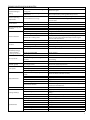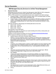
1
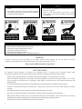
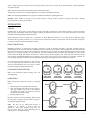
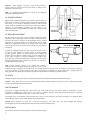
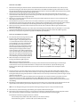
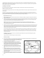
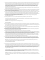
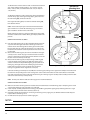
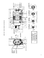
KINNEY® KMBD™ SERIES Mechanical Vacuum Boosters Models KMBD-4000 KMBD-6500 KMBD-8000 KMBD-9400 KMBD-10000 INSTALLATION OPERATION MAINTENANCE REPAIR MANUAL 1818 Rev. A 0912 ORIGINAL LANGUAGE - ENGLISH WARNING DO NOT OPERATE BEFORE READING MANUAL Tuthil Vacuum & Blower Systems 4840 West Kearney Street, P. O. Box 2877 Springfield, Missouri USA 65801-2877 Tel 417 865-8715 800 825-6937 Fax 417 865-2950 www.tuthillvacuumblower.com NOTICE SAFETY INSTRUCTIONS 1. Do not operate before reading the enclosed instruction manual. 2. Use adequate protection, warning and safety equipment necessary to protect against hazards involved in installation and operation of this equipment. 1. The safety instruction tags shown below were attached to your unit prior to shipment. Do not remove, paint over or obscure in any manner. 2. Failure to heed these warnings could result in serious bodily injury to the personnel operating and maintaining this equipment. ! WARNING Do not operate without guards in place SAFETY WARNINGS • Keep hands and clothing away from rotating machinery, inlet and discharge openings. • Booster and drive mounting bolts must be secured. • Drive belts and coupling guards must be in place. • Noise level may require ear protection. • Booster heat can cause burns if touched. TUTHILL VACUUM AND BLOWER SYSTEMS — SPRINGFIELD, MO USA IMPORTANT In order to assure you of the full benefits of our product warranty, please complete, tear out and return the warranty registration card located on the back cover of this manual, or you can register your product online at: http://vacuum.tuthill.com/product_registration SAFETY PRECAUTIONS For equipment covered specifically or indirectly in this instruction book, it is important that all personnel observe safety precautions to minimize the chances of injury. Among many considerations, the following should particularly be noted: • Booster casing and associated piping or accessories may become hot enough to cause major skin burns on contact. • Internal and external rotating parts of the booster and driving equipment can produce serious physical injuries. Do not reach into any opening in the booster while it is operating, or while subject to accidental starting. Cover external moving parts with adequate guards. • Disconnect power before doing any work, and avoid bypassing or rendering inoperative any safety or protective devices. • If booster is operated with piping disconnected, place a strong, coarse screen over the inlet and avoid standing in discharge air stream. • Avoid extended exposure in close proximity to machinery with high intensity noise levels. • Use proper care and good procedures in handling, lifting, installing, operating, and maintaining the equipment. • Other potential hazards to safety may also be associated with operation of this equipment. All personnel working in or passing through the area should be warned by signs and trained to exercise adequate general safety precautions. • Hearing protection may be required depending on silencing capabilities. 2 TABLE OF CONTENTS SECTION PAGE SAFETY PRECAUTIONS 2 INTRODUCTION 4 SPECIFICATIONS TABLE 4 CONFIGURATIONS 4 DESCRIPTION 4 TYPE OF LUBRICATION 4 INSTALLATION 5 GENERAL 5 PIPING CONNECTIONS 5 FLOW DIRECTION BY ROTATION 5 LUBRICATION 5 OIL CHANGE INTERVALS 6 OIL PRESSURE ADJUSTMENT 6 OIL FILTERS 6 HEAT EXCHANGER 6 MOTOR DRIVES 6 DIRECT COUPLED 7 V-BELT DRIVEN 7 ELECTRICAL CONNECTIONS 7 OPERATION 7 STARTING 7 OPERATING 7 STOPPING 7 MAINTENANCE 8 GENERAL 8 LONG TERM STORAGE 8 REPAIR SERVICE 8 MATERIAL SAFETY DATA SHEET 8 SPARE PARTS 8 TROUBLESHOOTING VACUUM BOOSTERS 9 FREQUENTLY ASKED QUESTIONS 10 ASSEMBLY AND DISASSEMBLY 10 DISASSEMBLY PROCEDURE 10 ASSEMBLY PROCEDURE 12 CLEARANCES 15 TORQUE CHART 15 BEARING & SEAL INSTALLATION TOOL DRAWINGS 16 PARTS LIST – MECHANICAL SEAL VERSION 18 CUTAWAY VIEW — MECHANICAL SEAL VERSION 19 PARTS LIST – SLINGER SEAL VERSION 20 CUTAWAY VIEW — SLINGER SEAL VERSION DETAILED VIEWS (APPLICABLE TO ALL VERSIONS) 21 22-23 VERTICAL FLOW DIMENSIONAL DRAWING 24 HORIZONTAL FLOW DIMENSIONAL DRAWING 25 WARRANTY – VACUUM PRODUCTS 26 3 INTRODUCTION CONGRATULATIONS on your purchase of a new KINNEY® KMBD™ Mechanical Vacuum Booster from Tuthill Vacuum & Blower Systems. Please examine the booster for shipping damage, and if any damage is found, report it immediately to the carrier. If the booster is to be installed at a later date make sure it is stored in a clean, dry location and rotated regularly. Make sure covers are kept on all openings. If blower is stored outdoors be sure to protect it from weather and corrosion. KINNEY Mechanical Vacuum Boosters are built to exacting standards and if properly installed and maintained will provide many years of reliable service. We urge you to take time to read and follow every step of these instructions when installing and maintaining your booster. We have tried to make these instructions as straightforward as possible. We realize getting any new piece of equipment up and running in as little time as possible is imperative to production. WARNING: Serious injury can result from operating or repairing this machine without first reading the service manual and taking adequate safety precautions. IMPORTANT: Record the booster model and serial numbers of your machine in the OPERATING DATA form on the inside back cover of this manual. You will save time and expense by including this reference identification on any replacement part orders, or if you require service or application assistance. This manual covers the installation, operation and maintenance of the mechanical vacuum boosters listed below: SPECIFICATIONS TABLE MODEL APPROXIMATE OIL CAPACITY GALLONS / LITERS VERTICAL HORIZONTAL KMBD-4000 KMBD-6500 KMBD-8000 10 / 38 7 / 26.5 KMBD-9400 KMBD-10000 * Maximum temperature is based on a 70° F (21° C) inlet temperature. PORT SIZE INCH / MM MAX. RPM 12 / 300 14 / 350 14 / 350 18 / 450 20 / 500 1800 MAX. DISCHARGE TEMPERATURE * °F/°C 350° / 177° 300° / 149° 270° / 132° For inlet temperatures below 70° F (21° C), maximum allowable temperature rise across the vacuum booster should also never exceed the following: KMBD-4000, 6500, 8000: 280 F° (156 C°) KMBD-9400: 230 F° (128 C°) KMBD-10000: 200 F° (111 C°) For inlet temperatures above 100° F (38° C), consult factory for maximum allowable discharge temperature. CONFIGURATIONS Kinney Vacuum Boosters are available in either vertical or horizontal flow direction, and with either mechanical face seals or noncontacting slinger seals. All KMBD-4000, 6500, 8000, 9400 & 10000 vacuum boosters also include pressure lubrication of bearings and seals. Gears are lubricated by dipping in the oil reservoir. DESCRIPTION Kinney vacuum boosters are lobe type, positive displacement units, designed with extra heavy shafts and bearings to permit high power input. They incorporate a unique rotor profile in which all gas joints or mating surfaces are sealed vacuum tight. Unit construction consists of two figure-eight shaped rotors enclosed in a precision machined housing supported at each end by precision bearings. The power drive turns the drive rotor directly and rotates the driven rotor by means of specially forged, heat treated, crowned and ground precision helical gears. Efficient and effective vacuum pumping is accomplished by trapping a volume of gas at the booster inlet and between each rotor and the booster housing. This volume of gas is quickly and cleanly evacuated by the fast revolving rotors which carry the air to the exhaust side of the booster where the air is then discharged to the backing pump. TYPE OF LUBRICATION All versions are equipped with integral lube systems having an oil pump, filter and cooler. Every Kinney Vacuum Booster is factory tested, oil drained, and shipped dry to its installation point. Oil reservoirs must be filled to proper level before operation. 4 Select a suitable low vapor pressure lubricant for high vacuum service such as Kinney AX oil (mineral-based), or Tuthill PneuLube™ oil (synthetic-based). Add vacuum oil to the booster in the quantity shown in Specifications Table. The end cover oil reservoirs are connected together by a 3-inch pipe at the bottom of the unit. NOTE: See “Frequently Asked Questions” on page 10 for additional information regarding lubrication. WARNING: Never attempt to change or add oil while booster is running. Failure to heed this warning could result in damage to the equipment or serious personal injury. INSTALLATION GENERAL Carefully check to ensure that no transit damage has been sustained. If damage has occurred from shipment a claim must be filed with the carrier immediately; preserve the shipping container for inspection by the carrier. Do not return the booster to the factory without first obtaining shipping instructions from us. Remove protective covers and plugs only as connections are made. Mount the booster on a flat, level surface of sufficient rigidity. Shim under the legs where necessary so as to have each leg of the booster support a proportional share of the booster weight. This is necessary to prevent eventual twisting of the booster. PIPING CONNECTIONS Manifolding should be no smaller than the pump connections in order to minimize restrictions to gas flow. Accurately align the mating flanges to the inlet and discharge manifolding to prevent distortion of the booster housing. Temporarily fit a fine wire mesh filter at the suction port if solid particles are likely to be entrained into the air stream and remove the filter when particles no longer appear. This is especially desirable on new installations and when manifolds have been welded. The manifolding to and from the booster should be fitted with flexible connections to isolate vibrations, absorb expansion and contraction due to thermal change, and to absorb misalignment differences. If the booster is to be water cooled, connect a clean supply to the 3/8” NPT connection on the seal adapter housing on all versions. Cooling of the bearing housing will prolong the life of the mechanical seal therein. An on-off valve should be provided on the incoming line and a regulating valve located in the drain line. The drain line should terminate at an open drain to enable the operator to better regulate the water flow. INTAKE DISCHARGE DISCHARGE INTAKE FLOW DIRECTION BY ROTATION Refer to the illustrations before installing inlet and discharge piping. LUBRICATION Before starting the booster fill reservoir as instructed below: 1. 2. 3. DISCHARGE INTAKE INTAKE DISCHARGE RIGHT DRIVE CW ROTATION RIGHT DRIVE CCW ROTATION LEFT DRIVE CW ROTATION LEFT DRIVE CCW ROTATION INTAKE Remove large hex head plug from free end plate. Pour oil through fill hole slowly until oil appears in sight glass. Slowly bring oil up to level between red markers. See Figure 3 at right. Let stand until oil stabilizes, then add as needed. Reinstall plug and secure. Oil levels should be checked frequently. Booster must be shut down to properly check oil level. See Figure 3 on the following page for detail. NOTE: Oil may not be added while booster is operating as oil reservoir is under vacuum. To change oil, drain from magnetic plug (31). You may also drain from any of the mounting feet by removing the 1-inch square head plug. DISCHARGE DISCHARGE TOP DRIVE CW ROTATION INTAKE TOP DRIVE CCW ROTATION INTAKE DISCHARGE DISCHARGE INTAKE BOTTOM DRIVE CW ROTATION BOTTOM DRIVE CCW ROTATION Figure 2 - Flow Direction by Rotation 5 WARNING: Never attempt to change or add oil while booster is running. Failure to heed this warning could result in damage to the equipment or personal injury. NOTE: See “Frequently Asked Questions” on page 10 information regarding lubrication. for additional OIL CHANGE INTERVALS MAX OIL LEVEL MIN OIL LEVEL Higher booster operating temperatures are directly related to higher oil temperatures. The initial oil change should be made after approximately 1000 hours or one month of operation, whichever comes first. Oil change frequency thereafter will depend upon operating conditions. Check for oil contamination periodically. For best results, an oilsampling program is recommended. Time between oil changes should never exceed 6 months. MOUNTING FOOT NON-DRIVE END OIL PRESSURE ADJUSTMENT The oil pressure on your unit has been preset at the factory during the performance test and generally should not require resetting once the unit has been placed in operation. Some adjustment may be required depending on operating speed and oil temperatures. The oil pump itself has no adjustment, however the oil by-pass relief valve located in the oil feed line after the oil filter can be used for the same purpose. See Figure 4. To make this adjustment, remove the hex cap, loosen the lock nut and turn the set screw clockwise to increase pressure or counterclockwise to lower pressure. Replace cap before taking pressure reading. Oil pressure may vary between 5 PSIG (.34 bar g) and 30 PSIG (2.07 bar g). The unit’s oil system can operate satisfactorily at 1 PSIG (.07 bar g), if necessary, and still have sufficient flow. Allow unit to reach normal operating temperature before resetting oil pressure. Set pressure at approximately 15 PSIG (1.03 bar g). Figure 3. Detailed view of oil level gauge REMOVE HEX CAP TO ADJUST IN OUT Figure 4. Inlet Suction Elbow NOTE: Vacuum boosters covered in this manual also include a compound oil pressure/vacuum gauge. This gauge may show vacuum readings due to the evacuation of the end covers, even through positive oil pressure exists. For example: If the booster is operating at 29” Hg (-.98 mbar g) vacuum (assume 29” Hg [-.98 bar g] vacuum in oil chamber) and the pressure gauge is reading 4” Hg (-.14 mbar g) vacuum, the oil pressure is actually at 25” Hg (29-4) or approximately 12 PSI (.84 bar g) positive pressure. OIL FILTERS Change the oil filter element with every oil change. Filter elements are available from Tuthill Vacuum & Blower Systems. CAUTION: Using filters other than those recommended by Tuthill Vacuum & Blower Systems will result in lubrication problems and cause unwarrantable damage to the booster. HEAT EXCHANGER All versions are supplied with four-pass coolers. Either hole can be used for water inlet with no effect on performance. For most applications, 2-5 GPM (7.5-20 L/min) of 60° F (15° C) water is generally sufficient. Actual water usage will depend on operating conditions. Ideal oil temperature range is 140° F (60° C) to 160° F (72° C). All standard coolers are designed for use with fresh water only. Do not use brackish or salt water. The liquid to be cooled (oil) flows around the tubes and the cooling liquid (water) flows through the tubes. --------- CAUTION: Never introduce hot media into a cold heat exchanger or cold media into a hot heat exchanger. The resulting thermal shock may cause premature failure allowing shell side and tube side liquids to mix. MOTOR DRIVES The two drive connections commonly used are, direct drive and V-belt drive. 6 DIRECT COUPLED When installing the motor directly to the booster, align shafts to coupling in accordance with the coupling manufacturer’s instructions. Boosters shipped with motor directly coupled and mounted on a common base have been aligned prior to shipment and normally no further alignment is necessary. However, alignment should be checked and adjustments made if necessary prior to starting the unit. V-BELT DRIVEN If the motor and booster are V-belt connected, the sheaves on both motor and booster shafts, should be as close to the shaft bearings as possible. Properly align the sheaves. V-belts should be replaced in matched sets and the sheaves should be positioned so as to allow the belts to be placed in the grooves without rolling them onto the sheaves. The following tensioning steps can be safely followed for all belt types, cross sections, number of belts per drive, or type of construction. 1. 2. 3. With belts properly in their grooves adjust the sheaves until all slack has been taken up. Start the drive and continue to tension the V-belt(s) until only a slight bow on the slack side of the drive appears while operating under load conditions. After 24 to 48 hours of operation the belts will seat in the sheave grooves. Further tensioning is then necessary as described in Step 2. Insufficient tensioning is often indicated by slipping (squealing) at start up. Belt dressing should not be used on V-belts. Sheaves and V-belts should remain free of oil and grease. Tension should be removed from belts if the drive is to be inactive for an extended period of time. For more specific information consult the drive manufacturer. ELECTRICAL CONNECTIONS Wire the motor and other electrical devices such as solenoid valves and temperature switch to the proper voltage and amperage as indicated on the nameplate of each component being wired. Turn the booster by hand after wiring is completed to determine that there are no obstructions and if the booster turns freely; then momentarily start the booster to check the direction of rotation. Figure 2 on page 7 shows direction of air flow in relation to rotor rotation. The air flow direction can be reversed by reversing the appropriate motor leads. OPERATION STARTING Check the oil level in the sight glass. It should be at the center of the glass. Add or drain oil as necessary to bring the oil to the correct level. Start the backing pump. When pressure is sufficiently reduced, start the booster. A pressure switch can be installed to start the booster at a predetermined pressure. If the booster is water cooled, turn on the cooling water when the booster is started. Adjust the water flow so that the discharge water temperature is no more than lukewarm, 70 to 80° F (21 to 27° C). OPERATING The upper temperature limits for booster pump operation are 270° to 350° F (132° to 177° C) measured in the exhaust gas stream with a low mass thermocouple. When this temperature limit switch is installed, as the temperature exceeds the predetermined temperature, the booster motor will stop and cannot be restarted until the temperature drops below the trip setting of the temperature switch. NOTE: These upper limits are not for continuous operation. Consult with factory for detailed information or assistance. STOPPING Stop the booster by turning off the motor. Isolate the booster from the vacuum system and vent the booster to atmosphere. Turn off the cooling water if water cooled. Stop the backing pump. Refer to component instruction manual. CAUTION: Venting the booster to pressures above cut-in while running can damage the pump. 7 MAINTENANCE GENERAL Scheduled maintenance consists of changing lubricating oil every 1500 to 3000 hours of operation. Change the oil more frequently if pumping corrosive vapors or where excessive operating temperatures are encountered. Proper oil drain schedules require oil be changed before the contaminant load becomes so great that the oil’s lubricating function is impaired or heavy disposition of suspended contaminants occurs. To check the condition of the oil, drain a sampling into a clean container and check for the presence of water or solids. Slight discoloration of the oil should not necessitate an oil change. NOTE: When changing oil be sure to reseal the drain and fill plugs. Oil levels should be checked every 24 hours of operation. When a booster is taken out of service, it may require internal protection against rusting or corrosion. The need for such protection must be a matter of judgment based on existing conditions as well as length of down time. Under atmospheric conditions producing rapid corrosion, the blower should be protected immediately. Regular inspection of the booster and its installation, along with complete checks on operating conditions will pay dividends in added life and usefulness. Service the drive per manufacturer’s instructions and lubricate the coupling or check belt drive tension. By use of thermometers and gauges, make sure that booster operating temperature and pressure remains within allowed limits. LONG TERM STORAGE 1. 2. 3. 4. 5. 6. 7. Spray the interior (lobes, housing and end plates) with rust preventative. Fill both end bells completely full of oil. Firmly attach a very prominent tag stating that the end bells are full of oil and must be drained and refilled to proper levels prior to startup. Apply rust preventative grease to the drive shaft. Attach a desiccant bag to either of the port covers to prevent condensation from occurring inside the booster. Make sure any desiccant bags are so attached to the covers that they will be removed before startup of the blower. Store the booster in an air-conditioned and heated building if at all possible. At least insure as dry conditions as possible. If possible, rotate the drive shaft by hand at least monthly in order to prevent the seals from setting in one position. REPAIR SERVICE With proper care, Tuthill Vacuum & Blower Systems Mechanical Vacuum Boosters will give years of reliable service. The parts are machined to very close tolerances and require special tools by mechanics who are skilled at this work. Should major repairs become necessary, it is strongly recommended that the booster be returned to the factory for repair or to one of the authorized service facilities that specialize in vacuum booster repair. Contact the factory for the location nearest you. Units which are still under warranty must be returned to the factory, freight prepaid, for service. MATERIAL SAFETY DATA SHEET Current regulations require a Material Safety Data Sheet to be completed and forwarded to Tuthill Vacuum & Blower Systems on any unit being returned for any reason, which has been handling or involved with hazardous gases or materials. This is for the protection of our employees who are required to perform service on this equipment. Failure to do so will result in needless delays. SPARE PARTS Refer to the parts list and exploded view for your particular model. Repair kits are available for all models. These kits contain all of the seals, bearings, O-rings, locks and special retaining screws necessary for an overhaul. Always have complete booster model number and serial number when ordering. In developing a stock of spare parts, consider the following: • The degree of importance in maintaining the booster in a “ready” condition. • The time lag in parts procurement. • Cost. • Shelf life (seals and O-rings). Contact Tuthill Vacuum & Blower Systems Service Department for any assistance in selecting spare parts. Telephone: (417) 865-8715 8 Toll Free (48 contiguous states): (800) 825-6937 Facsimile: (417) 865-2950 TROUBLESHOOTING VACUUM BOOSTERS PROBLEM Booster knocking or rapping Excessive operating temperatures. Lack of volume. Abnormal bearing and gear wear. POSSIBLE CAUSES Unit out of time from worn bearings or timing gears Rotors contacting due to high temperature. Loss of oil. High oil pressure (>25 PSIG [1.7 bar g]) New installation Existing installation Low oil pressure. Belts slip (sidewalls glazed) Drive squeals. Belt(s) turned over. Breakage of belt(s). Rapid belt wear. Reduce temperature by lowering differential pressure. Driver or booster loose. Worn seals. Drive shaft seal leaking. Leaking plugs. Factory set at lower RPM. Adjust bypass relief valve. Faulty gauge. Broken or leaking hose or fitting (internal). Oil pump worn. Orifices clogging. Remove and blow out with shop air. Replace. Remove access plates in cover and replace or re-tighten hose or fitting. Replace. Not enough tension. Replace belts; apply proper tension. Shock load. Not enough arc of contact. Heavy starting load. Broken cord caused by prying on sheave. Overloaded drive. Impulse loads. Misalignment of sheave and shaft. Worn sheave grooves. Apply proper tension. Increase center distance. Increase belt tension. Slipping V-belts. Worn clearances. Inadequate lubrication. Unbalanced or rubbing rotors. Excessive belt vibration. Mismatched belts. Replace worn gears. Reduce pressure across booster by lowering cut-in pressure. Check blank-off pressure of backing pump, and check system for leaks. Tighten or replace belts. Re-establish clearances. Maintain correct oil levels. Improve frequency of oil changes. Initiate oil sampling program. Re-align drive. Check gear backlash and condition of bearings. Scale or process material may build up on housing and rotor surfaces, or inside rotors. Remove buildup to restore original clearances and rotor balance. Tighten mounting bolts securely. Replace seals. Replace seal. Re-seal and tighten plugs. Pressure differential too high. Misalignment. Worn bearings and/or gears. Excessive vibration. SOLUTION New belts installed with old belts. Shock loads. Heavy starting loads. Belt pried over sheaves. Foreign objects in drives. Sheave grooves worn. Sheave diameter too small. Mismatched belts. Drive overloaded. Belt slips. Sheaves misaligned. Oil or heat condition. Replace set of belts and install correctly. Redesign drive. Apply proper tension. Realign drive. Replace sheaves. Check drive design. Check equipment for solid mounting. Consider use of banded belts. Replace belts in matched sets only. Apply proper tension; recheck drive. Apply proper tension; recheck drive. Use compensator starting. Replace set of belts correctly. Provide drive guard. Replace sheaves. Redesign drive. Replace with matched belts. Redesign drive. Increase tension. Align sheaves. Eliminate oil. Ventilate drive. 9 FREQUENTLY ASKED QUESTIONS What are the perceived modes of failure when units are run beyond the specified duty cycles? Several things are happening as the lubricant goes through the unit. First, it is absorbing frictional energy in the form of heat. This heat has to be dissipated through either surface contact with cooler materials, or in a rest volume of lubricant. While reducing the friction, the lubricant is also going through a shearing process and the molecular structure is broken down. The result is that the lubricant will begin to thicken. Because of the shorter molecular chains and the drop out of additive packages. The thickened lubricant will cause more drag, increasing the friction and heat, and further degrading the lubricant. Operation of the blower (environment, run time, speed, and pressure) has a direct effect on duty cycles. Our published cycles are based on worst-case conditions. What is the functional detriment if the “wrong oil” is used? The lubricant is selected based on bearing and gear speed, and operating temperature. Too light of a lubricant increases wear by not separating the sliding surfaces and it will not remove the heat adequately. If the lubricant is too thick, the drag in the bearings is increased causing them to run hotter. Since it is thicker, it will not flow as readily into the gears and it will reduce the available backlash. Lubricants at our conditions are incompressible. What is the functional detriment if the oil is not serviced? If the lubricant is not serviced at the proper interval the shearing action in the bearing and the gears will begin to take their toll and the lubricant will thicken, making matters worse. The unit will run hotter and the wear on running surfaces will increase. Generally, the lubricant will appear dirtier, this is actually material rubbed off the unit’s components. The discoloration comes from overheating the additive package. An indicator of the breakdown of a lubricant is the increase in the TAN (Total Acid Number), and a change in the base viscosity of ten percent. ASSEMBLY AND DISASSEMBLY DISASSEMBLY PROCEDURE 1. Drain lubricant from either end and disconnect all the external oil lines. Do not attempt to remove the oil distribution line bushings in the non-drive end plate until the end cover has been removed and the internal fittings are disconnected. The oil filter and heat exchanger may be removed or can be left fastened to the cover. Mark piping and other parts so that they can go back in their original position when reassembling. FREE END DISASSEMBLY 2. Remove three nuts and washers (116 & 117) and pull the oil pump assembly (144) with the extension (313) from the cover. It is not necessary to disconnect these two parts unless the oil pump is to be replaced. CAUTION: Do not attempt to remove cover with oil pump attached. 3. 4. Support free end cover (7) using a lifting strap. Remove cap screws (26) and reinstall two of them as jack screws in the tapped holes next to the dowel pins. It is recommended that two studs 8” long be used to assist in supporting the cover unit until it has cleared the dowel pins. Remove large O-ring (302). Disconnect oil tubing and remove cap screws (30) from angle drive. Carefully tap this assembly free from end plate. It is held in location by a spring pin (311). ANGLE DRIVE DISASSEMBLY 5. 10 If the unit is being completely overhauled the four bearings in this assembly should be replaced. Refer to drawing on page 21 and proceed as follows: a. Remove flat head socket screw (22851) and retainer washer (92147) from each gear. b. Support bearing housing and tap shafts (14197 & 14167) through gears and bearings. Keep spacers and shims with respective gear. c. Remove button head screws (91211) and retainers (92148). From the opposite side, tap out bearings (8522 & 92141) and spacers (92142). d. Reassemble in reverse order. GEAR END DISASSEMBLY 6. Remove drive shaft key (23). Remove all burrs and other defacements from the drive shaft. Remove cap screws (30 & 93). Pry off seal housing (91) and remove stator portion of mechanical seal (76B). Discard O-ring (314). Loosen both set screws (90) and remove retaining ring (78). Using an appropriate spanner wrench, remove the adapter sleeve (87) by turning counter clockwise. Remove mating ring (76A) and O-rings (88 & 140). 7. Support drive end cover (6) as done on the non-drive end. Remove cap screws (26). The drive end cover also has jack screw holes but it must slide off a special roller bearing on the drive shaft. To keep the bearing outer race from cocking, it is suggested that the tool shown in Figure 8 be used. 8. Remove cap screws (66) and drive shaft (45). The bearing (50) should be pulled now unless it is to be pressed apart after drive shaft has been removed. 9. Stand the blower up on the non-drive end on 6” x 6” blocks. Remove the cap screws (326) from the driven gear and align the match marks on the timing gear teeth (8). Using a suitable puller or extended pry bars, remove the gear shells from their hubs. The shell and hub are matched, do not interchange. Remark if the original markings are no longer visible. 10. Unlock spanner nut lock washers (36) and remove spanner nuts (35) and lock washers. Remove gear hubs with puller. Remove gear keys (24). 11. Remove oil sight gauge (70). Remove cap screws (307) and mounting feet (304 & 408). All feet are mounted on 1-1/8” hollow locating dowels (306) from which they should easily disengage by tapping lightly with a mallet. Discard O-rings (305). 12. Remove cap screws (30) bearing retainer rings (14) and end plate cap screws (301). END PLATE AND ROTOR DISASSEMBLY 13. The end plate, with the bearings, must be pulled from the rotor shafts. Make up two plates as shown in Figure 5, along with eight pieces of ½ -13 all thread, flat washers and hex nuts. The use of a hydraulic ram is also recommended but some modifications may be necessary depending on the type of equipment available. Install each plate to the bearing retainer ring mounting holes and apply pressure equally to the ends of the rotor shaft by tightening the nuts on the threaded rods. Install spacers under plates after rotor shafts become flush with top of bearing. Use a hoist to pick up the end plate once the bearings have cleared the shaft ends. 14. After the end plate is removed, tap out the bearings (9). Remove large O-ring (176). 4.52 4.48 3.02 2.98 Ø .531 4 HOLES 8.510 8.490 30° TYP 3/4 - 10 TAP 6.04 5.96 4.255 4.245 9.04 8.96 1.01 .99 Figure 5. Bearing Pressing Fixture NOTE: If the rotor shaft sleeves (239) were removed with the end plate, (mechanical seal version) you must drive them out with the bearings. To avoid damage to the sleeves do not use any hard faced hammers or steel punches to drive them out. Separate the mating rings from the sleeves. Pull out (by hand) the stator portion of the mechanical seal (54). Retain the seal adapters (74) for reassembly. 15. Slinger Seal Version: Each rotor shaft has two sleeves (197 & 239) with a slinger seal (238) sandwiched in between. If the inner sleeve (197) remains on the shaft, remove and place on top of slinger and drive entire assembly including lip seal and bearing from end plate using same precaution as noted above. It is not necessary to remove stator portion of slinger seal (79) unless it is to be replaced. Mechanical Seal Version: To replace the PTFE washers of the labyrinth seals, remove the retaining ring (219), two wave springs (282), steel spacers (281), and PTFE washers (280). NOTE: Older units will contain six PTFE and seven steel washers in each bore. The current PTFE washers are thicker, therefore you will only use five PTFE and six steel washers when reassembling. 16. Reinstall the end plate without the bearings and seals and secure with six cap screws equally spaced. Turn the unit over and support with blocks under the gear end plate. Repeat steps 10, 13, 14 and 15 to remove non-drive end plate. NOTE: Do not damage bearing spacers (123) when removing bearings. This spacer is only used on the free end. 17. Lift the rotors (1) out of the housing (3). Unbolt the gear end plate and lift the housing off. 18. Clean all the parts and inspect for wear. It is not necessary to remove the oil distribution fittings on the end plates and the gear cover but they should be checked with compressed air to be sure the five orifices are not clogged. The diameters of the bearing or gear journals are as follows: All rotor shaft journals (either end) 3.5439”/3.5435” (90.015 mm/90.005 mm)*. Drive shaft bearing journal – 3.9372”/3.9366” (100.005 mm/99.990 mm). 11 *This dimension on older rotors may be .0005” (.013 mm) less than shown. It is acceptable providing shafts show no signs of fretting, corrosion or spun bearings. Dimensions for other machined parts are available upon request by contacting the Tuthill Vacuum & Blower Systems Service Department. ASSEMBLY PROCEDURE The assembly procedure is generally the same for both slinger seal and mechanical seal versions, but where there are differences, notations will be made. All joints between housing, end plates, and covers are O-ring sealed. An RTV Silicone sealer or equal is used on the lip seals and mounting feet. Dowel pins are used to locate end plates, housing, and covers in the proper location relative to each other. Be sure they are in place. It is recommended that the gear end rotor shaft bearings be purchased from Tuthill Vacuum & Blower Systems, as they are specially ground to locate the rotors with correct end clearance relative to the gear end plate. PREPARATION OF END PLATES 1. 2. Make sure all parts are clean and free of any nicks or burrs caused by disassembly. See pages 11 through 13 for dimensions of seal installation tools. Mechanical Seal Version: Position end plates with bearing bores up (flange side down) and install components of labyrinth seals. Starting with a PTFE washer (280) alternately stack five PTFE and five steel spacers in each seal bore. Add two wave springs, one more steel spacer and a retaining ring. Compress to seat seal. NOTE: Two wave springs are necessary for the proper pressure on the seal, but because of this pressure a tool as shown in Figure 5 on page 13 is needed to press the retainer ring into its groove. The tool will center the labyrinth seal as it presses the retainer ring in place. 3. Mechanical Seal Version: Install the seal adapter (74). The adapter is used to anchor the stator portion of the mechanical seal (54). To install the seal, grease both the O-ring and seal bore, then push the seal, by hand, into the bore and against the seal adapter, making sure the two dimples on the bottom of the seal case are aligned with the holes in the seal adapter. Clean surface of carbon with soft tissue and acetone. Units manufactured with mechanical seals requiring a press fit will not use item 74 (seal adapter). A special tool shown on page 13 is needed for proper installation. In this case a sealer is applied to the seals O.D. To press on the seal tool use the bearing plates, studs, nuts and washers. Carefully run nuts down equally until seal is seated. Clean surface of carbon with soft tissue and acetone. CAUTION: Never drive mechanical seal or seal tool with any type of hammer. This could result in damage to the carbon or its ability to properly seal. Slinger Seal Version: Install new slinger seal stators if necessary GEAR END ASSEMBLY 4. 5. 6. 7. 8. 12 Place non-drive end plate on 6” x 6” blocks with the solid side up. The end plate must be blocked up so rotor shafts will not touch floor when they are installed. Grease and install O-ring (176) in end plate groove. Install housing (3) making sure dowel pins are in place. Do not bolt in place at this time. Lay two pieces of steel approximately 2” x 20” x 1/8” thick at the bottom of the housing parallel to the two bores, then install both rotors into the housing as shown in Figure 11 with the gear end (long shaft) up. The rotor lobes will be above the end of the housing which is necessary when assembling this end. Grease and install O-ring (176) in groove of gear end plate. Use sufficient grease to hold it in place when the end plate is turned over. Install the end plate on the rotors and housing. the end plate will rest on the ends of the rotor lobes, and there will be a space between the housing and the plate. Install all the cap screws (301) and, applying equal forces to the cap screws, draw the housing tight to the end plate. Use six cap screws (301) equally spaced and secure non-drive end plate against shims at bottom end of rotors. Do not torque these Figure 6. Arrangement of Rotors in Housing bolts. 9. 10. 11. 12. 13. Mechanical Seal Version: Grease O-ring (331) and start onto rotor shaft. Grease internal O-ring of mating ring portion of seal (54). Assemble mating ring over sleeve (239) with lapped surface down. Slot in mating ring must line up with pin in sleeve and be flush with top of sleeve when properly installed. Clean lapped surface of mating ring with soft tissue and acetone. Lubricate surface and start sleeve over rotor shaft while forcing O-ring into step at bottom of sleeve. Carefully slide this assembly down the shaft until seated. You may encounter interference as the sleeve passes through the PTFE rings. Tap sleeve with mallet to seat if necessary. Slinger Seal Version: Install sleeves (197) (2.45” [62.2 mm] long) slingers (238) and sleeves (239) on each shaft. Install lip seal with lip facing upward using tool shown on page 12. Coat the rotor shafts with an anti-seize lubricant and press the bearings (9) on the shafts. The bearing manufacturer numbers and/or an acid dot (inner race) should be up or toward the gears. Use the same plates used in disassembly and a sleeve to press on the inner race of bearing when installing. Loosen cap screws holding non-drive end plate to housing then install bearing retainer rings (14) and secure with cap screws (30). At this time check clearance between rotor lobes and gear end plate. See page 20 for correct gear end clearances. If clearances are not within specifications, recheck parts to find cause of improper clearances before proceeding. Retighten the cap screws on the non-drive end but do not torque at this time. Install keys (24) in rotor shafts. Tight fit required. Coat shafts and key with anti-seize. If new gears are being installed, disassemble shells from hubs. Heat the gear hubs to 350° F (177° C). At this temperature they should fit easily on the rotor shafts. Secure with lock washers (36) and lock nut (35) immediately after hub is installed. Torque to proper specifications. Do not install gear shell at this time. Allow to cool. WARNING: Handle heated gear hubs with insulated gloves only. FREE END ASSEMBLY 14. Turn assembly over and support it on blocks. Remove the six screws and put jackscrews in holes provided in flange of end plate and remove plate. Take out the two shims and check free end clearances between end of lobes and housing using a flat bar and feeler gauges or a depth micrometer. See page 20 for correct clearances. 15. Mechanical Seal Version: Recheck carbon of seal to be sure it is clean. All versions: Reinstall end plate making sure O-ring is still in its groove and secure with all the cap screws (26). 16. Repeat step 9 to install sleeve and mating ring assemblies or slinger seal parts. 17. Install bearing spacers (123) then repeat step 10 to install bearings. Secure with lock washers and lock nuts (36 & 35). Bend one lock washer tab into spanner nut slot to lock (all nuts). 18. Mechanical Seal Version: Install oil retainer rings (15) and cap screws (30) (only six required). Slinger Seal Version: Reassemble angle drive (310) in reverse of disassembly instructions step 5. Install complete assembly to end plate making sure spring pin (311) is in place and secure with cap screws (30). Reconnect all oil tubing. 19. To install the mounting feet (304 & 408) the hollow dowel (306) should be in the foot. If any of the dowels are in the end plate, remove and transfer to the feet. Grease and install the O-ring over dowel. Run a bead of silicone sealer, ¼” (6.3 mm) wide, around the dowel hole on the foot mounting pad of the end plate. This acts as a backup O-ring to prevent any oil leakage. Secure with cap screws (307). Reconnect oil sight glass then stand unit on its feet. 20. The gear hubs should now be cool enough to assemble the gear shells. The dowel pins should be in the hubs. Transfer if necessary. Reinstall the timing shim and assemble the shells to their proper hubs (align hub and shell match marks). Install drive gear first (right-handed helix) then align the match marks on the teeth and assemble driven gear (left-handed helix). NOTE: The six cap screws which were in the drive gear are too long without the drive shaft. Temporarily use the six cap screws from the driven gear. Use three in each gear (every other hole). ADJUSTING INTERLOBE CLEARANCE 21. The timing gears are made up of two pieces. The outer gear shells are fastened to the inner hubs with six cap screws and located with two dowel pins. By adding shims between a gear shell and the inner hub the gear is moved axially relative to the inner hub which is mounted on the rotor shaft. Being a helical gear, it rotates as it is moved out and the rotor turns changing the clearances between rotor lobes. Adding .012” (.30 mm) shim thickness will change the rotor lobe clearance by .003” (.076 mm). The timing shim is formed from a number of .003 (.075 mm) shims, which have been laminated together. They are easily peeled off as necessary. Use feeler gauges to check the clearance at AA (right-hand reading) and BB (left-hand reading). See Figure 12 below. The clearances should be adjusted so they are as equal between all lobes as possible. Usually within .003” to .004” (.076 mm .10 mm). For best results use feeler gauges no longer than .006” (.15 mm). EXAMPLE: If AA reading is .030” (.76 mm) and BB reading is .022” (.56 mm), by removing .016” (.40 mm) shim, the readings will change one-quarter of this amount or .004” (.10 mm). AA reading will drop to .026” (.66 mm) and BB reading will increase to .026” (.66 mm). 13 To determine the amount of shim to add or remove from the driven gear, simply subtract the two readings .030” (.76 mm -.022” (55 mm) = .008” (.21 mm) and double the result .008 (.21 mm) x 2 = .016 (.42 mm). Record A-A Reading Here To determine whether to add or remove this amount the following rule will always apply: If the right reading (AA) is greater than the left side reading (BB), remove this amount. If the right side reading (AA) is less than the left side reading (BB), then add this amount. B A A COMPLETING DRIVE END ASSEMBLY 22. Press drive shaft bearing (50) on drive shaft (45). Remove the three cap screws from drive gear and install in driven gear. Clean and remove all burrs from mating surfaces of the gear and drive shaft flange. Install with cap screws (66). Torque gear cap screws at this time. Check drive shaft run out at seal journal. Do not exceed .005” (.13 mm) T.I.R. 23. Grease and install O-ring (302). To aid in the installation of the gear cover (6) a tool as shown on page 12 should be made to hold the outer race of the bearing square with the shaft. Slide the cover over the tool and secure with cap screws (26). 24. Grease and install O-ring (140) on adapter flange and O-ring (88) in bore of adapter. Clean mating ring (76A) with soft tissue and acetone and install on adapter while aligning pin (300) with slot in mating ring. The larger surface area of mating ring faces inward. Install retaining ring (78). Screw on adapter and seat against bearing using spanner wrench. Tighten set screws (90). A A NOTE: If the results require you to remove shim from the driven gear and there are no shims left under this gear, go to the drive gear and add this amount for the same results. When removing or replacing a gear for shimming, the timing mark should be matched and on center. Either gear may be pulled in this position. B B B Long Feeler Gauge Record B-B Reading Here A A B B B B A A Figure 7. Checking Interlobe Clearances Lubricate seal O-ring and hand press seal (76B) into seal housing (91) making sure to align the two dimples on the bottom of the seal with corresponding holes in seal housing. Clean carbon surface with soft tissue and acetone. Grease and install Oring (314) around seal bore. Place a few drops of lubricating oil on mating ring then carefully install assembly over drive shaft onto cover. Secure with cap screws (30 & 93). NOTE: To install press fit drive shaft seal refer to page 15 for recommended tools. COMPLETING FREE END ASSEMBLY 25. Make sure all internal oil tubing has been installed and connected. Grease and install O-ring (302) in end plate groove. Install cover (7) with dowel pins and secure with cap screws (26). 26. Install oil pump assembly (144) extension housing (313) and O-ring (325) while aligning pump shaft tang with slot in angle drive shaft. Secure with lock washer and nuts (116 & 117). 27. Complete assembly by reinstalling or connecting all remaining oil lines, sight glass, etc. Oil filter element should always be replaced when overhauling a unit. 28. Fill with lubricant to proper level on column sight glass. NOTES: 14 CLEARANCES Values shown in inches and millimeters. MODEL GEAR END FREE END KMBD-4000 .020 - .027 .51 - .69 KMBD-6500 .029 - .036 .74 - .91 KMBD-8000 .011 - .014 .28 - .36 .035 - .042 .89 - 1.07 KMBD-9400 .041 - .048 1.04 - 1.22 KMBD-10000 .053 - .060 1.35 - 1.52 INTERLOBE TIP-DOWEL TIP-PORT .025 - .032 .64 - .81 .012 - .019 .30 - .48 .021 - .027 .53 - .69 TORQUE CHART MAXIMUM TORQUE PART DESCRIPTION FT. - LBS. N-m 5/16-18 CAP SCREW 17 23 1/2-13 CAP SCREW 50 68 5/8-11 CAP SCREW 90 122 GEAR & BEARING LOCK NUT 300 408 ITEM NUMBERS NOT SHOWN ON ASSEMBLY DRAWING ITEM NO. DESCRIPTION QTY. REQUIRED (ALL VERSIONS) 124 Oil Filter (Complete) 1 173 Heat Exchanger 1 262 Oil Pressure Gauge 1 265 Oil Bypass Relief Valve 1 15 BEARING & SEAL INSTALLATION TOOL DRAWINGS 0.25 1.62 15° 1.0 Ø 4.75 Ø 4.50 Ø 6.235 6.230 Ø 4.00 CHAMFER .040 × 45° Ø 7.475 7.470 .06 R MATERIAL: MILD STEEL 8.0 Figure 8. Seal Installation Tool 6.02 5.98 2.02 1.98 1.51 1.49 SETSCREW 3/8 - 16UNC × .50 LG Ø 4.26 4.24 Ø 5.32 5.30 Ø 3.510 3.505 Ø 7.083 7.080 .065 .055 .065 .055 1.13 1.11 Figure 9. Drive Shaft Bearing Alignment Tool 16 MATERIAL: MILD STEEL BEARING & SEAL INSTALLATION TOOL DRAWINGS 8.01 7.99 6.01 5.99 .060 × 45° Ø 7.475 7.470 Ø 6.000 5.990 Ø 5.01 4.99 .065 R .055 MATERIAL: MILD STEEL 3.01 2.99 Ø 6.740 6.730 Ø 6.240 6.235 .51 .49 1.01 .99 Figure 10. Mechanical Seal Installation Tool (For Press Fit Seals Only) Ø 6.258 6.256 Ø 8.01 7.99 Ø 7.085 7.084 .21 .19 1.01 .99 MATERIAL: MILD STEEL Figure 11. Pilot Tool for Mechanical Seal Installation in Drive Shaft Seal Housing 17 PARTS LIST – MECHANICAL SEAL VERSION ITEM NO. VERT. FLOW HORIZ. FLOW ITEM NO. DESCRIPTION VERT. FLOW HORIZ. FLOW 1 Rotor 2 2 117 Lockwasher 3 3 3 Housing 1 1 123 Bearing Spacer 2 2 4 End Plate 2 1 124 Oil Filter * 1 1 Dowel Pin 4 4 5 End Plate (Free End) — 1 126 6 Drive End Cover 1 1 128 Oil Tube 1 — 7 Free End Cover 1 1 140 O-Ring 1 1 8 Timing Gear Set 1 1 144 Lube Pump Assembly 1 1 9 Bearing (Gear End) 2 2 173 Heat Exchanger * 1 1 10 Bearing (Free End) 2 2 174 Pipe Plug 1/2” NPT AR AR 12 Lip Seal — — 176 O-Ring 2 2 14 Bearing Retainer 2 2 197 Sleeve — — 22 Dowel Pin 4 4 219 Retaining Ring 4 4 Cap Screw 6 6 23 Drive Shaft Key 1 1 225 24 Gear Key 2 2 238 Oil Slinger (Seal) — — 26 Cap Screw 48 48 239 Sleeve 4 4 27 Lockwasher 4 4 261 Elbow 2 2 30 Cap Screw 23 23 262 Compound Gauge * 1 1 31 Magnetic Pipe Plug 1 1 265 Relief Valve * 1 1 35 Locknut 4 4 266 Hose Clamp 4 4 36 Lockwasher 4 4 280 PTFE Washer 20 20 45 Drive Shaft 1 1 281 Spacer 24 24 Wave Spring 8 8 50 Bearing 1 1 282 54 Mechanical Seal 4 4 300 Spring Pin 5 5 66 Screw 6 6 301 Cap Screw 48 48 69 Hex Head Cap Screw 4 4 302 O-Ring 2 2 70 Oil Sight Glass 1 1 303 Cover Plate 1 1 71 Adapter (Sight Glass) 1 1 304 Mounting Foot 3 3 72 Adapter 1 1 305 O-Ring 4 4 74 Adapter 4 4 306 Sleeve (Foot) 4 4 Seal Mating Ring 1 1 307 Cap Screw 16 16 Angle Drive Assembly 1 1 76A 18 DESCRIPTION 76B Seal Stator 1 1 310 78 Retainer Ring 1 1 311 Spring Pin 1 1 79 Oil Retainer (Seal) — — 313 Lube Pump Ext. Hsg. 1 1 85 Pipe Plug 4 4 314 O-Ring 2 2 87 Adapter 1 1 317 Spring Pin 1 1 88 O-Ring 1 1 325 O-Ring 2 2 90 Socket Head Cap Screw 2 2 329 Plug (Oil Fill) 1 2 91 Seal Adapter Housing 1 1 331 O-Ring 4 4 93 Cap Screw 4 4 336 Orifice * 4 4 Oil Tube — 1 Mounting Foot 1 1 107 Sleeve (Oil Tube) 2 2 358 115 Stud 1/4’-20 x 1.25” 3 3 408 116 Hex Nut 1/4”-20 3 3 * Not shown in Assembly Drawings 19 S 311 123 INSTALL PUMP WITH SUCTION PORT TOWARD DRIVE END OF BLOWER. “S” ON PUMP INDICATES SUCTION PORT. 144 69 27 313 115 116 117 310 325 317 30 314 305 30 235 7 10 54 4 74 22 107 266 215 280 281 282 358 1 (SERIES 31 USES ITEM 128) 3 331 176 300 301 4 302 14 CUTAWAY VIEW — MECHANICAL SEAL VERSION 9 8 314 45 78 300 87 23 30 (2 REQ.) 93 (4 REQ.) 91 76B 140 85 90 88 6 35 36 24 31 174 66 50 76A 126 26 30 PARTS LIST – SLINGER SEAL VERSION ITEM NO. 20 DESCRIPTION VERT. FLOW HORIZ. FLOW ITEM NO. DESCRIPTION VERT. FLOW HORIZ. FLOW 1 Rotor 2 2 117 Lockwasher 3 3 3 Housing 1 1 123 Bearing Spacer 2 2 4 End Plate 2 1 124 Oil Filter * 1 1 Dowel Pin 4 4 5 End Plate (Free End) — 1 126 6 Drive End Cover 1 1 128 Oil Tube 1 — 7 Free End Cover 1 1 140 O-Ring 1 1 8 Timing Gear Set 1 1 144 Lube Pump Assembly 1 1 9 Bearing (Gear End) 2 2 173 Heat Exchanger * 1 1 10 Bearing (Free End) 2 2 174 Pipe Plug 1/2” NPT AR AR 12 Lip Seal 4 4 176 O-Ring 2 2 14 Bearing Retainer 2 2 197 Sleeve 4 4 Retaining Ring — — 22 Dowel Pin 4 4 219 23 Drive Shaft Key 1 1 225 Cap Screw 6 6 24 Gear Key 2 2 238 Oil Slinger (Seal) 4 4 26 Cap Screw 48 48 239 Sleeve 4 4 27 Lockwasher 4 4 261 Elbow 2 2 30 Cap Screw 23 23 262 Compound Gauge * 1 1 31 Magnetic Pipe Plug 1 1 265 Relief Valve * 1 1 35 Locknut 4 4 266 Hose Clamp 4 4 PTFE Washer — — 36 Lockwasher 4 4 280 45 Drive Shaft 1 1 281 Spacer — — 50 Bearing 1 1 282 Wave Spring — — 54 Mechanical Seal — — 300 Spring Pin 1 1 66 Screw 6 6 301 Cap Screw 48 48 69 Hex Head Cap Screw 4 4 302 O-Ring 2 2 70 Oil Sight Glass 1 1 303 Cover Plate 1 1 Mounting Foot 3 3 71 Adapter (Sight Glass) 1 1 304 72 Adapter 1 1 305 O-Ring 4 4 74 Adapter — — 306 Sleeve (Foot) 4 4 76A Seal Mating Ring 1 1 307 Cap Screw 16 16 76B Seal Stator 1 1 310 Angle Drive Assembly 1 1 78 Retainer Ring 1 1 311 Spring Pin 1 1 79 Oil Retainer (Seal) 4 4 313 Lube Pump Ext. Hsg. 1 1 85 Pipe Plug 4 4 314 O-Ring 2 2 Spring Pin 1 1 87 Adapter 1 1 317 88 O-Ring 1 1 325 O-Ring 2 2 90 Socket Head Cap Screw 2 2 329 Plug (Oil Fill) 1 2 91 Seal Adapter Housing 1 1 331 O-Ring — — 93 Cap Screw 4 4 336 Orifice * 4 4 107 Sleeve (Oil Tube) 2 2 358 Oil Tube — 1 115 Stud 1/4’-20 x 1.25” 3 3 408 Mounting Foot 1 1 116 Hex Nut 1/4”-20 3 3 * Not shown in Assembly Drawings 21 S 311 123 4 INSTALL PUMP WITH SUCTION PORT TOWARD DRIVE END OF BLOWER. “S” ON PUMP INDICATES SUCTION PORT. 144 65 27 313 115 116 117 325 310 317 30 314 303 30 235 7 10 12 79 22 266 107 358 1 (SERIES 35 USES ITEM 128) 3 197 176 238 301 4 CUTAWAY VIEW — SLINGER SEAL VERSION 14 302 26 30 126 31 9 50 76A 66 314 30 76B 91 93 174 35 36 87 300 23 45 88 78 85 90 140 8 6 24 DETAILED VIEWS (APPLICABLE TO ALL VERSIONS) 92143 SPACER 92142 SPACER (2 REQ.) 92141 BEARING (2 REQ.) 8522 BEARING (2 REQ.) 14169 GEAR 14198 RETAINER 22851 SCREW (2 REQ.) 92147 RETAINER 14168 GEAR 92144 92145 92146 SHIM AS REQ. FOR MT'G DIM. 2 PLACES 1,875 1,872 MT'G DIM. 14197 SHAFT 92148 RETAINER (2 REQ.) 91211 SCREW (8 REQ.) 14170 SPACER 22874 KEY (2 REQ.) 92137 BRACKET 14167 SHAFT 2,000 MT'G 1,997 DIM. SHIM AS REQUIRED FOR MT'G DIM 22 ANGLE DRIVE ASSEMBLY (ITEM 310) DETAILED VIEWS (APPLICABLE TO ALL VERSIONS) 325 O-RING BOSS PLUG 72 70 71 408 OIL SIGHT GAUGE DETAIL FREE END (FAR SIDE) 307 306 305 225 261 FOOT DETAIL 304 (3 PLACES) 23 24 2 3/4 5 1/2 OIL LEVEL SIGHT GAUGE OIL PUMP OIL FILTER RELIEF VALVE VACUUM/PRESSURE GAUGE 3/4 NPT COOLING WATER CONNECTIONS. INLET OR OUTLET CAN BE EITHER PORT. C E D B 23 1/8 17 1/4 THE DIMENSIONS SHOWN TO THE RIGHT APPLY TO BOTH THE VERTICAL FLOW CONFIGURATION ON THIS PAGE AND THE HORIZONTAL FLOW CONFIGURATION SHOWN ON OPPOSITE PAGE. OIL FILL PLUG (1) (FARSIDE) SHOWN ON NEARSIDE FOR CLARITY A 16 5/16 Ø 3.4995 ± .0005 5 3/4 5 7/8 G 29 5/16 B 35 3/8 39 7/8 42 7/8 45 7/8 51 7/8 65 3/4 74 3/4 80 3/4 86 3/4 98 3/4 KMBD-4000 KMBD-6500 KMBD-8000 KMBD-9400 KMBD-10000 C F 46 7/8 40 7/8 37 7/8 34 7/8 E 28 3/4 57 1/2 45 1/2 39 1/2 19 3/4 24 1/2 33 1/2 22 3/4 COOLING WATER OUTLET 1/4 NPT 32 5/16 20 18 14 14 12 2 2 1 1/4 1 1/4 1 1/8 F G MAGNETIC DRAIN PLUG 6 3 5/16 13 13 16 3/4 12 1/4 D FLANGE 18 5/16 30 3/8 27 3/4 A 3 13 7/8 6 36 11/16 MODEL Ø 1 1/32 4 HOLES 2 COOLING WATER INLET 1/4 NPT 7/8 SQ KEY INSTRUMENTATION CONNECTION 1/2 NPT (2) EA PORT (SEE DETAIL) VERTICAL FLOW DIMENSIONAL DRAWING MODEL A 25 B 22 Ø 1 1/32 4 HOLES 40 1/2 C D E MAGNETIC DRAIN PLUG COOLING WATER INLET 1/4 NPT INSTRUMENTATION CONNECTION 1/2 NPT (2) EA PORT (SEE DETAIL) 13 3 F G 28 15° 16 23 1/8 17 1/4 5 1/2 1 Ø 12 19 7/8-9UNC x 1 3/4 DP - 12 HOLES EQ SP ON A Ø 17 BC 12" FLANGE 5 7/8 5 3/4 Ø 3.4995 ± .0005 ALTERNATE DRIVE SHAFT LOCATION COOLING WATER OUTLET 1/4 NPT 7 3/16 6 FLANGE F 7/8 SQ KEY G THE FLANGES SHOWN TO THE RIGHT APPLY TO BOTH THE HORIZONTAL FLOW CONFIGURATION ON THIS PAGE AND THE VERTICAL FLOW CONFIGURATION SHOWN ON OPPOSITE PAGE. 14 3/8 26 15° Ø 14 Ø 21 2 3/4 18" FLANGE Ø 18 Ø 25 OIL PUMP 3/4 NPT COOLING WATER CONNECTIONS. INLET OR OUTLET CAN BE EITHER PORT. 9° OIL FILTER OIL COOLER RELIEF VALVE VACUUM/PRESSURE GAUGE 20" FLANGE Ø 20 Ø 27 1/2 1 1/8-7UNC x 2 DP 20 HOLES EQ SP ON A Ø 25 BC OIL SIGHT GAUGE 1 1/8-7UNC x 2 DP 16 HOLES EQ SP ON A Ø 22 3/4 BC C NOTE: ALL FLANGES 125/150 LB ANSI DRILLING 11 1/4° E A 1-8UNC x 2 DP 12 HOLES EQ SP ON A Ø 18 3/4 BC D 14" FLANGE B OIL FILL PLUG (1) EA END PLATE HORIZONTAL FLOW DIMENSIONAL DRAWING WARRANTY – VACUUM PRODUCTS Subject to the terms and conditions hereinafter set forth and set forth in General Terms of Sale, Tuthill Vacuum & Blower Systems (the seller) warrants products and parts of its manufacture, when shipped, and its work (including installation and start-up) when performed, will be of good quality and will be free from defects in material and workmanship. This warranty applies only to Seller’s equipment, under use and service in accordance with seller’s written instructions, recommendations and ratings for installation, operating, maintenance and service of products, for a period as stated in the table below. Because of varying conditions of installation and operation, all guarantees of performance are subject to plus or minus 5% variation. (Non-standard materials are subject to a plus or minus 10% variation). PRODUCT TYPE WARRANTY DURATION New 15 months after date of shipment or 12 months after initial startup date, whichever occurs first Repair 6 months after date of shipment or remaining warranty period, whichever is greater Remanufactured 9 months after date of shipment or 6 months after initial startup date, whichever occurs first THIS WARRANTY EXTENDS ONLY TO BUYER AND/OR ORIGINAL END USER, AND IN NO EVENT SHALL THE SELLER BE LIABLE FOR PROPERTY DAMAGE SUSTAINED BY A PERSON DESIGNATED BY THE LAW OF ANY JURISDICTION AS A THIRD PARTY BENEFICIARY OF THIS WARRANTY OR ANY OTHER WARRANTY HELD TO SURVIVE SELLER’S DISCLAIMER. All accessories furnished by Seller but manufactured by others bear only that manufacturer’s standard warranty. All claims for defective products, parts, or work under this warranty must be made in writing immediately upon discovery and, in any event within one (1) year from date of shipment of the applicable item and all claims for defective work must be made in writing immediately upon discovery and in any event within one (1) year from date of completion thereof by Seller. Unless done with prior written consent of Seller, any repairs, alterations or disassembly of Seller’s equipment shall void warranty. Installation and transportation costs are not included and defective items must be held for Seller’s inspection and returned to Seller’s Ex-works point upon request. THERE ARE NO WARRANTIES, EXPRESSED, IMPLIED OR STATUTORY WHICH EXTEND BEYOND THE DESCRIPTION ON THE FACE HEREOF, INCLUDING WITHOUT LIMITATION, THE IMPLIED WARRANTIES OF MERCHANTABILITY AND FITNESS OF PURPOSE. After Buyer’s submission of a claim as provided above and its approval, Seller shall at its option either repair or replace its product, part, or work at the original Ex-works point of shipment, or refund an equitable portion of the purchase price. The products and parts sold hereunder are not warranted for operation with erosive or corrosive material or those which may lead to build up of material within the product supplied, nor those which are incompatible with the materials of construction. The Buyer shall have no claim whatsoever and no product or part shall be deemed to be defective by reason of failure to resist erosive or corrosive action nor for problems resulting from build-up of material within the unit nor for problems due to incompatibility with the materials of construction. Any improper use, operation beyond capacity, substitution of parts not approved by Seller, or any alteration or repair by others in such manner as in Seller’s judgment affects the product materially and adversely shall void this warranty. No employee or representative of Seller other than an Officer of the Company is authorized to change this warranty in any way or grant any other warranty. Any such change by an Officer of the Company must be in writing. The foregoing is Seller’s only obligation and Buyer’s only remedy for breach of warranty, and except for gross negligence, willful misconduct and remedies permitted under the General Terms of Sale in the sections on CONTRACT PERFORMANCE, INSPECTION AND ACCEPTANCE and the PATENTS Clause hereof, the foregoing is BUYER’S ONLY REMEDY HEREUNDER BY WAY OF BREACH OF CONTRACT, TORT OR OTHERWISE, WITHOUT REGARD TO WHETHER ANY DEFECT WAS DISCOVERED OR LATENT AT THE TIME OF DELIVERY OF THE PRODUCT OR WORK. In no event shall Buyer be entitled to incidental or consequential damages. Any action for breach of this agreement must commence within one (1) year after the cause of action has occurred. February, 2008 26 OPERATING DATA It is to the user’s advantage to have the requested data filled in below and available in the event a problem should develop in the blower or the system. This information is also helpful when ordering spare parts. Model No. V-Belt Size: Length: Serial No. Type of Lubrication: Startup Date Pump RPM Operating Vacuum Pump Sheave Diameter: Any other special accessories supplied or in use: Motor Sheave Diameter: Motor RPM HP NOTES: IMPORTANT All mechanical vacuum boosters manufactured by Tuthill Vacuum & Blower Systems are date coded at time of shipment. In order to assure you of the full benefits of the product warranty, please complete, tear out and return the product registration card below, or you can visit our product registration web page at: http://vacuum.tuthill.com/product_registration IMPORTANT All KINNEY® vacuum pumps manufactured by Tuthill Vacuum & Blower Systems are date coded at time of shipment. In order to assure you of the full benefits of the product warranty, please complete, tear out and return this product registration card. Company ________________________________________________________________ Location__________________________________________________________________ City State/Province ZIP/Postal Code Country Telephone : ( )_____________________ E-mail: _________________________ Model: _________________________ Serial Number: _________________________ Date of Purchase: _________________________ Date of Startup: _________________________ PLEASE CHECK ONE Vacuum Furnace Vacuum Coating Pharmaceutical Semiconductor/Electronics Food/Meat Packing Gas/Petrochemical Other _________________________ BUSINESS REPLY MAIL FIRST-CLASS MAIL PERMIT NO. 2912 SPRINGFIELD MO POSTAGE WILL BE PAID BY ADDRESSEE ATTN. CUSTOMER SERVICE – VACUUM PRODUCTS TUTHILL VACUUM & BLOWER SYSTEMS PO BOX 2877 SPRINGFIELD MO 65890-2150 NO POSTAGE NECESSARY IF MAILED IN THE UNITED STATES