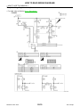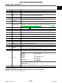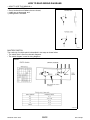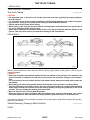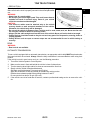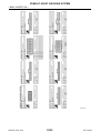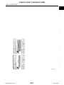
1
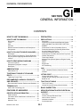
GENERAL INFORMATION
SECTION
GI
GENERAL INFORMATION
GI
B
C
D
E
CONTENTS
F
HOW TO USE THIS MANUAL ...................... 3
PRECAUTION .............................................. 24
HOW TO USE THIS MANUAL ............................ 3
PRECAUTIONS ................................................. 24
Description ................................................................ 3
Terms ........................................................................ 3
Units .......................................................................... 3
Contents .................................................................... 3
Relation between Illustrations and Descriptions ...... 4
Components .............................................................. 4
Description ...............................................................24
Precaution for Supplemental Restraint System
(SRS) "AIR BAG" and "SEAT BELT PRE-TENSIONER" .................................................................24
Precautions For Xenon Headlamp Service .............24
Precaution Necessary for Steering Wheel Rotation after Battery Disconnect ...................................24
Precaution for Battery Service .................................25
Precaution for Procedure without Cowl Top Cover....25
General Precautions ................................................25
Three Way Catalyst .................................................27
Multiport Fuel Injection System or Engine Control
System .....................................................................27
Hoses ......................................................................27
Engine Oils ..............................................................28
Air Conditioning .......................................................29
G
FUEL ..........................................................................29
FUEL : Unleaded Premium Gasoline Recommended ....................................................................29
L
LIFTING POINT ................................................. 30
M
Commercial Service Tools .......................................30
Garage Jack and Safety Stand and 2-Pole Lift .......30
Board-On Lift ...........................................................31
N
HOW TO FOLLOW TROUBLE DIAGNOSES ..... 6
Description ................................................................ 6
How to Follow Test Groups in Trouble Diagnosis...... 6
Key to Symbols Signifying Measurements or Procedures ..................................................................... 7
HOW TO READ WIRING DIAGRAMS ................ 9
Connector symbols ................................................... 9
Sample/wiring diagram -example- ........................... 10
Description .............................................................. 11
ABBREVIATIONS ..............................................13
Abbreviation List ...................................................... 13
TIGHTENING TORQUE OF STANDARD
BOLTS ................................................................14
Tightening Torque Table ......................................... 14
RECOMMENDED CHEMICAL PRODUCTS
AND SEALANTS ................................................15
Recommended Chemical Products and Sealants.... 15
Tow Truck Towing ...................................................32
Vehicle Recovery (Freeing a Stuck Vehicle) ...........32
SAE J1930 Terminology List ................................... 16
BASIC INSPECTION ................................... 34
FEATURES OF NEW MODEL ..................... 20
SERVICE INFORMATION FOR ELECTRICAL
INCIDENT .......................................................... 34
Model Variation ....................................................... 20
Information About Identification or Model Code ...... 20
Dimensions ............................................................. 22
Wheels & Tires ........................................................ 23
Revision: 2007 June
I
J
K
TOW TRUCK TOWING ..................................... 32
TERMINOLOGY .................................................16
IDENTIFICATION INFORMATION .....................20
H
GI-1
Work Flow ................................................................34
Control Units and Electrical Parts ............................34
How to Check Terminal ...........................................35
Intermittent Incident .................................................38
Circuit Inspection .....................................................41
G37 Coupe
O
P
CONSULT-III/GST CHECKING SYSTEM ......... 46
Description .............................................................. 46
CONSULT-III Function and System Application*1... 46
Revision: 2007 June
GI-2
CONSULT-III/GST Data Link Connector (DLC)
Circuit ...................................................................... 47
Wiring Diagram - CONSULT-III/GST CHECKING
SYSTEM - ............................................................... 48
G37 Coupe
HOW TO USE THIS MANUAL
< HOW TO USE THIS MANUAL >
HOW TO USE THIS MANUAL
GI
HOW TO USE THIS MANUAL
Description
INFOID:0000000001679165
This volume explains “Removal, Disassembly, Installation, Inspection and Adjustment” and “Trouble Diagnoses”.
Terms
B
C
INFOID:0000000001679166
• The captions WARNING and CAUTION warn you of steps that must be followed to prevent personal injury
and/or damage to some part of the vehicle.
WARNING indicates the possibility of personal injury if instructions are not followed.
CAUTION indicates the possibility of component damage if instructions are not followed.
BOLD TYPED STATEMENTS except WARNING and CAUTION give you helpful information.
Standard value: Tolerance at inspection and adjustment.
Limit value: The maximum or minimum limit value that should not be exceeded at inspection and adjustment.
Units
D
E
F
INFOID:0000000001679167
• The UNITS given in this manual are primarily expressed as the SI UNIT (International System of Unit), and
alternatively expressed in the metric system and in the yard/pound system.
Also with regard to tightening torque of bolts and nuts, there are descriptions both about range and about the
standard tightening torque.
G
H
“Example”
Range
I
Outer Socket Lock Nut
: 59 - 78 N·m (6.0 - 8.0 kg-m, 43 - 58 ft-lb)
J
Standard
Drive Shaft Installation Bolt
: 44.3 N·m (4.5 kg-m, 33 ft-lb)
K
Contents
INFOID:0000000001679168
• ALPHABETICAL INDEX is provided at the end of this manual so that you can rapidly find the item and page
you are searching for.
• A QUICK REFERENCE INDEX, a black tab (e.g.
) is provided on the first page. You can quickly find the
first page of each section by matching it to the section's black tab.
• THE CONTENTS are listed on the first page of each section.
• THE TITLE is indicated on the upper portion of each page and shows the part or system.
• THE PAGE NUMBER of each section consists of two or three letters which designate the particular section
and a number (e.g. “BR-5”).
• THE SMALL ILLUSTRATIONS show the important steps such as inspection, use of special tools, knacks of
work and hidden or tricky steps which are not shown in the previous large illustrations.
Assembly, inspection and adjustment procedures for the complicated units such as the automatic transaxle
or transmission, etc. are presented in a step-by-step format where necessary.
L
M
N
O
P
Revision: 2007 June
GI-3
G37 Coupe
HOW TO USE THIS MANUAL
< HOW TO USE THIS MANUAL >
Relation between Illustrations and Descriptions
INFOID:0000000001679169
The following sample explains the relationship between the part description in an illustration, the part name in
the text and the service procedures.
SAIA0519E
Components
INFOID:0000000001679170
• THE LARGE ILLUSTRATIONS are exploded views (see the following) and contain tightening torques, lubrication points, section number of the PARTS CATALOG (e.g. SEC. 440) and other information necessary to
perform repairs.
The illustrations should be used in reference to service matters only. When ordering parts, refer to the appropriate PARTS CATALOG.
Components shown in an illustration may be identified by a circled number. When this style of illustration is
used, the text description of the components will follow the illustration.
Revision: 2007 June
GI-4
G37 Coupe
HOW TO USE THIS MANUAL
< HOW TO USE THIS MANUAL >
GI
B
C
D
E
SFIA2959E
1.
Union bolt
2.
Copper washer
3.
Brake hose
4.
Cap
5.
Bleed valve
6.
Sliding pin bolt
7.
Piston seal
8.
Piston
9.
Piston boot
10. Cylinder body
11.
Sliding pin
12.
Torque member mounting bolt
13. Washer
14.
Sliding pin boot
15.
Bushing
16. Torque member
17.
Inner shim cover
18.
Inner shim
19. Inner pad
20.
Pad retainer
21.
Pad wear sensor
22. Outer pad
23.
Outer shim
24.
Outer shim cover
1: PBC (Poly Butyl Cuprysil) grease
or silicone-based grease
2: Rubber grease
F
G
H
I
: Brake fluid
Refer to GI section for additional symbol definitions.
J
SYMBOLS
K
L
M
N
SAIA0749E
O
P
Revision: 2007 June
GI-5
G37 Coupe
HOW TO FOLLOW TROUBLE DIAGNOSES
< HOW TO USE THIS MANUAL >
HOW TO FOLLOW TROUBLE DIAGNOSES
Description
INFOID:0000000001679171
NOTICE:
Trouble diagnoses indicate work procedures required to diagnose problems effectively. Observe the following
instructions before diagnosing.
• Before performing trouble diagnoses, read the “Work Flow” in each section.
• After repairs, re-check that the problem has been completely eliminated.
• Refer to Component Parts and Harness Connector Location for the Systems described in each section for
identification/location of components and harness connectors.
• When checking circuit continuity, ignition switch should be OFF.
• Refer to the Circuit Diagram for quick pinpoint check.
If you need to check circuit continuity between harness connectors in more detail, such as when a sub-harness is used, refer to Wiring Diagram in each individual section and Harness Layout in PG section for identification of harness connectors.
• Before checking voltage at connectors, check battery voltage.
• After accomplishing the Diagnosis Procedures and Electrical Components Inspection, make sure that all
harness connectors are reconnected as they were.
How to Follow Test Groups in Trouble Diagnosis
INFOID:0000000001679172
JPAIA0021GB
1.
2.
3.
4.
Test group number and test group title
• Test group number and test group title are shown in the upper portion of each test group.
Work and diagnosis procedure
• Start to diagnose a problem using procedures indicated in enclosed test groups.
Questions and results
• Questions and required results are indicated in test group.
Action
• Next action for each test group is indicated based on result of each question.
Revision: 2007 June
GI-6
G37 Coupe
HOW TO FOLLOW TROUBLE DIAGNOSES
< HOW TO USE THIS MANUAL >
Key to Symbols Signifying Measurements or Procedures
INFOID:0000000001679173
GI
B
C
D
E
F
G
H
I
SAIA1539E
J
K
L
M
N
O
P
Revision: 2007 June
GI-7
G37 Coupe
HOW TO FOLLOW TROUBLE DIAGNOSES
< HOW TO USE THIS MANUAL >
SAIA1540E
Revision: 2007 June
GI-8
G37 Coupe
HOW TO READ WIRING DIAGRAMS
< HOW TO USE THIS MANUAL >
HOW TO READ WIRING DIAGRAMS
Connector symbols
GI
INFOID:0000000001679174
Most of connector symbols in wiring diagrams are shown from the terminal side.
• Connector symbols shown from the terminal side are enclosed by
a single line and followed by the direction mark.
• Connector symbols shown from the harness side are enclosed by
a double line and followed by the direction mark.
• Certain systems and components, especially those related to
OBD, may use a new style slide-locking type harness connector.
For description and how to disconnect, refer to PG section,
“Description”, “HARNESS CONNECTOR”.
B
C
D
E
F
G
H
SAIA0257E
I
• Male and female terminals
Connector guides for male terminals are shown in black and
female terminals in white in wiring diagrams.
J
K
L
M
N
O
SGI363
Revision: 2007 June
GI-9
G37 Coupe
P
HOW TO READ WIRING DIAGRAMS
< HOW TO USE THIS MANUAL >
Sample/wiring diagram -example-
INFOID:0000000001679175
• For detail, refer to following GI-11, "Description".
JCAWA0005GB
Revision: 2007 June
GI-10
G37 Coupe
HOW TO READ WIRING DIAGRAMS
< HOW TO USE THIS MANUAL >
Description
INFOID:0000000001679176
GI
Number
Item
Description
B
1
Power supply
• This means the power supply of fusible link or fuse.
2
Fusible link
• “X” means the fusible link.
3
Number of fusible link/
fuse
• This means the number of fusible link or fuse location.
4
Fuse
• “/” means the fuse.
5
Current rating of fusible link/fuse
• This means the current rating of the fusible link or fuse.
6
Optional splice
• The open circle shows that the splice is optional depending on vehicle application.
7
Connector number
• The letter shows which harness the connector is located in.
• Example “M”: main harness. For detail and to locate the connector, refer to PG-74, "How
To Read Harness Layout", PG-76, "Main Harness".
8
Splice
• The shaded circle “
9
Page crossing
• This circuit continues to an adjacent page.
10
Option abbreviation
• This means the vehicle specifications which layouts the circuit between “
11
Relay
• This shows an internal representation of the relay.
12
Option description
• This shows a description of the option abbreviation used on the page.
13
Switch
• This shows that continuity exists between terminals 1 and 2 when the switch is in the A
position. Continuity exists between terminals 1 and 3 when the switch is in the B position.
14
Circuit (Wiring)
• This means the wiring.
15
System branch
• This shows that the circuit is branched to other systems.
16
Shielded line
• The line enclosed by broken line circle shows shield wire.
17
Component name
• This shows the name of a component.
18
Ground (GND)
• This shows the ground connection.
19
Connector
• This means the connector information.
• This unit-side is described by the connector symbols.
20
Connectors
• This means that a transmission line bypasses two connectors or more.
C
D
” means the splice.
E
F
”.
G
H
I
J
K
• This shows a code for the color of the wire.
21
Wire color
BR = Brown
OR or O = Orange
P = Pink
PU or V (Violet) = Purple
GY or GR = Gray
SB = Sky Blue
CH = Dark Brown
DG = Dark Green
B = Black
W = White
R = Red
G = Green
L = Blue
Y = Yellow
LG = Light Green
L
M
• When the wire color is striped, the base color is given first, followed by the stripe color as
shown below:
Example: L/W = Blue with White Stripe
22
Terminal number
N
O
• This means the terminal number of a connector.
SWITCH POSITIONS
Switches are shown in wiring diagrams as if the vehicle is in the “normal” condition.
A vehicle is in the “normal” condition when:
Revision: 2007 June
GI-11
P
G37 Coupe
HOW TO READ WIRING DIAGRAMS
< HOW TO USE THIS MANUAL >
• ignition switch is “OFF”,
• doors, hood and trunk lid/back door are closed,
• pedals are not depressed, and
• parking brake is released.
SGI860
MULTIPLE SWITCH
The continuity of multiple switch is described in two ways as shown below.
• The switch chart is used in schematic diagrams.
• The switch diagram is used in wiring diagrams.
JSAIA0017GB
Revision: 2007 June
GI-12
G37 Coupe
ABBREVIATIONS
< HOW TO USE THIS MANUAL >
ABBREVIATIONS
GI
Abbreviation List
INFOID:0000000001679177
The following ABBREVIATIONS are used:
B
ABBREVIATION
DESCRIPTION
A/C
Air Conditioner
A/T
Automatic Transaxle/Transmission
ATF
Automatic Transmission Fluid
D1
Drive range 1st gear
D2
Drive range 2nd gear
D3
Drive range 3rd gear
D4
Drive range 4th gear
FR, RR
Front, Rear
LH, RH
Left-Hand, Right-Hand
C
D
E
F
M/T
Manual Transaxle/Transmission
OD
Overdrive
P/S
Power Steering
SAE
Society of Automotive Engineers, Inc.
SDS
Service Data and Specifications
SST
Special Service Tools
2WD
G
H
2-Wheel Drive
22
2nd range 2nd gear
21
2nd range 1st gear
12
1st range 2nd gear
11
1st range 1st gear
I
J
K
L
M
N
O
P
Revision: 2007 June
GI-13
G37 Coupe
TIGHTENING TORQUE OF STANDARD BOLTS
< HOW TO USE THIS MANUAL >
TIGHTENING TORQUE OF STANDARD BOLTS
Tightening Torque Table
Grade
4T
7T
9T
Bolt size
Bolt diameter *
mm
INFOID:0000000001679178
Tightening torque (Without lubricant)
Pitch
mm
Hexagon head bolt
N·m
M6
6.0
M8
8.0
M10
10.0
M12
12.0
1.25
M14
14.0
1.5
M6
6.0
1.0
M8
8.0
M10
10.0
M12
12.0
M14
kg-m
Hexagon flange bolt
ft-lb
in-lb
N·m
kg-m
ft-lb
in-lb
1.0
5.5
0.56
4
49
7
0.71
5
62
1.25
13.5
1.4
10
—
17
1.7
13
—
1.0
13.5
1.4
10
—
17
1.7
13
—
1.5
28
2.9
21
—
35
3.6
26
—
1.25
28
2.9
21
—
35
3.6
26
—
1.75
45
4.6
33
—
55
5.6
41
—
45
4.6
33
—
65
6.6
48
—
80
8.2
59
—
100
10
74
—
9
0.92
7
80
11
1.1
8
97
1.25
22
2.2
16
—
28
2.9
21
—
1.0
22
2.2
16
—
28
2.9
21
—
1.5
45
4.6
33
—
55
5.6
41
—
1.25
45
4.6
33
—
55
5.6
41
—
1.75
80
8.2
59
—
100
10
74
—
1.25
80
8.2
59
—
100
10
74
—
14.0
1.5
130
13
96
—
170
17
125
—
M6
6.0
1.0
11
1.1
8
—
13.5
1.4
10
—
M8
8.0
1.25
28
2.9
21
—
35
3.6
26
—
1.0
28
2.9
21
—
35
3.6
26
—
M10
10.0
1.5
55
5.6
41
—
80
8.2
59
—
1.25
55
5.6
41
—
80
8.2
59
—
M12
12.0
1.75
100
10
74
—
130
13
96
—
1.25
100
10
74
—
130
13
96
—
M14
14.0
1.5
170
17
125
—
210
21
155
—
*: Nominal diameter
1.
Special parts are excluded.
2.
This standard is applicable to bolts having the following marks embossed on the bolt head.
MGI044A
Revision: 2007 June
GI-14
G37 Coupe
RECOMMENDED CHEMICAL PRODUCTS AND SEALANTS
< HOW TO USE THIS MANUAL >
RECOMMENDED CHEMICAL PRODUCTS AND SEALANTS
Recommended Chemical Products and Sealants
GI
INFOID:0000000001679179
Refer to the following chart for help in selecting the appropriate chemical product or sealant.
1
2
3
Product Description
Purpose
Rear View Mirror Adhesive
Used to permanently remount rear view mirrors to
windows.
Anaerobic Liquid Gasket
For metal-to-metal flange
sealing.
Can fill a 0.38 mm (0.015
inch) gap and provide instant sealing for most powertrain applications.
High Performance
Thread Sealant
Provides instant sealing on
any threaded straight or
parallel threaded fitting.
(Thread sealant only, no
locking ability.)
• Do not use on plastic.
Gasket Maker
4
Nissan North America
Part No. (USA)
999MP-AM000P
6
99998-50505
Medium Strength
Thread Locking Sealant (Blue)
Threadlocker
Threadlocker (service tool
removable)
Permatex 81844
D
999MP-AM001P
99998-50503
Permatex 51813 and
51817
E
F
999MP-AM002P
999MP-AM002P
Permatex 56521
G
999MP-AM003P
(Ultra Grey)
99998-50506
(Ultra Grey)
Silicone RTV
High Temperature,
High Strength Thread
Locking Sealant (Red)
Aftermarket Crossreference Part Nos.
C
Gasket Maker for Maxima/
Quest 5-speed automatic
transmission
(RE5F22A)
5
Nissan Canada Part
No. (Canada)
B
–
999MP-AM004P
999MP-AM005P
Permatex Ultra Grey
82194;
Three Bond
1207,1215, 1216,
1217F, 1217G and
1217H
Nissan RTV Part No.
999MP-A7007
H
I
Three Bond 1281B
or exact equivalent in
its quality
J
K
999MP-AM004P
Permatex 27200;
Three Bond 1360,
1360N, 1305 N&P,
1307N, 1335,
1335B, 1363B,
1377C, 1386B, D&E
and 1388
Loctite 648
999MP-AM005P
Permatex 24200,
24206, 24240,
24283 and 09178;
Three Bond 1322,
1322N, 1324 D&N,
1333D, 1361C,
1364D, 1370C and
1374
–
L
M
N
O
P
Revision: 2007 June
GI-15
G37 Coupe
TERMINOLOGY
< HOW TO USE THIS MANUAL >
TERMINOLOGY
SAE J1930 Terminology List
INFOID:0000000001679180
All emission related terms used in this publication in accordance with SAE J1930 are listed. Accordingly, new
terms, new acronyms/abbreviations and old terms are listed in the following chart.
NEW ACRONYM /
ABBREVIATION
NEW TERM
OLD TERM
Air cleaner
ACL
Air cleaner
Barometric pressure
BARO
***
Barometric pressure sensor-BCDD
BAROS-BCDD
BCDD
Camshaft position
CMP
***
Camshaft position sensor
CMPS
Crank angle sensor
Canister
***
Canister
Carburetor
CARB
Carburetor
Charge air cooler
CAC
Intercooler
Closed loop
CL
Closed loop
Closed throttle position switch
CTP switch
Idle switch
Clutch pedal position switch
CPP switch
Clutch switch
Continuous fuel injection system
CFI system
***
Continuous trap oxidizer system
CTOX system
***
Crankshaft position
CKP
***
Crankshaft position sensor
CKPS
***
Data link connector
DLC
***
Diagnostic test mode
DTM
Diagnostic mode
Diagnostic test mode selector
DTM selector
Diagnostic mode selector
Diagnostic test mode I
DTM I
Mode I
Diagnostic test mode II
DTM II
Mode II
Diagnostic trouble code
DTC
Malfunction code
Direct fuel injection system
DFI system
***
Distributor ignition system
DI system
Ignition timing control
Early fuel evaporation-mixture heater
EFE-mixture heater
Mixture heater
Early fuel evaporation system
EFE system
Mixture heater control
Electrically erasable programmable read
only memory
EEPROM
***
Electronic ignition system
EI system
Ignition timing control
Engine control
EC
***
Engine control module
ECM
ECCS control unit
Engine coolant temperature
ECT
Engine temperature
Engine coolant temperature sensor
ECTS
Engine temperature sensor
Engine modification
EM
***
Engine speed
RPM
Engine speed
Erasable programmable read only memory
EPROM
***
Evaporative emission canister
EVAP canister
Canister
Evaporative emission system
EVAP system
Canister control solenoid valve
Exhaust gas recirculation valve
EGR valve
EGR valve
Revision: 2007 June
GI-16
G37 Coupe
TERMINOLOGY
< HOW TO USE THIS MANUAL >
NEW ACRONYM /
ABBREVIATION
NEW TERM
OLD TERM
GI
Exhaust gas recirculation control-BPT
valve
EGRC-BPT valve
BPT valve
Exhaust gas recirculation control-solenoid
valve
EGRC-solenoid valve
EGR control solenoid valve
EGRT sensor
Exhaust gas temperature sensor
C
Flash electrically erasable programmable
read only memory
FEEPROM
***
D
Flash erasable programmable read only
memory
FEPROM
***
Flexible fuel sensor
FFS
***
Flexible fuel system
FF system
***
Fuel pressure regulator
***
Pressure regulator
Fuel pressure regulator control solenoid
valve
***
PRVR control solenoid valve
Fuel trim
FT
***
Heated Oxygen sensor
HO2S
Exhaust gas sensor
Idle air control system
IAC system
Idle speed control
Idle air control valve-air regulator
IACV-air regulator
Air regulator
Idle air control valve-auxiliary air control
valve
IACV-AAC valve
Auxiliary air control (AAC) valve
Idle air control valve-FICD solenoid valve
IACV-FICD solenoid valve
FICD solenoid valve
Idle air control valve-idle up control solenoid valve
IACV-idle up control solenoid valve
Idle up control solenoid valve
Idle speed control-FI pot
ISC-FI pot
FI pot
Idle speed control system
ISC system
***
Ignition control
IC
***
Ignition control module
ICM
***
Indirect fuel injection system
IFI system
***
Intake air
IA
Air
Intake air temperature sensor
IAT sensor
Air temperature sensor
Knock
***
Detonation
Knock sensor
KS
Detonation sensor
Malfunction indicator lamp
MIL
Check engine light
Manifold absolute pressure
MAP
***
Manifold absolute pressure sensor
MAPS
***
Manifold differential pressure
MDP
***
Manifold differential pressure sensor
MDPS
***
Exhaust gas recirculation temperature sensor
B
EGR temperature sensor
E
F
G
H
I
J
K
L
M
N
O
Manifold surface temperature
MST
***
Manifold surface temperature sensor
MSTS
***
Manifold vacuum zone
MVZ
***
Manifold vacuum zone sensor
MVZS
***
Mass air flow sensor
MAFS
Air flow meter
Mixture control solenoid valve
MC solenoid valve
Air-fuel ratio control solenoid valve
Multiport fuel injection system
MFI system
Fuel injection control
Revision: 2007 June
GI-17
P
G37 Coupe
TERMINOLOGY
< HOW TO USE THIS MANUAL >
NEW ACRONYM /
ABBREVIATION
NEW TERM
OLD TERM
Nonvolatile random access memory
NVRAM
***
On board diagnostic system
OBD system
Self-diagnosis
Open loop
OL
Open loop
Oxidation catalyst
OC
Catalyst
Oxidation catalytic converter system
OC system
***
Oxygen sensor
O2S
Exhaust gas sensor
Park position switch
***
Park switch
Park/neutral position switch
PNP switch
Park/neutral switch
Inhibitor switch
Neutral position switch
Periodic trap oxidizer system
PTOX system
***
Positive crankcase ventilation
PCV
Positive crankcase ventilation
Positive crankcase ventilation valve
PCV valve
PCV valve
Powertrain control module
PCM
***
Programmable read only memory
PROM
***
Pulsed secondary air injection control solenoid valve
PAIRC solenoid valve
AIV control solenoid valve
Pulsed secondary air injection system
PAIR system
Air induction valve (AIV) control
Pulsed secondary air injection valve
PAIR valve
Air induction valve
Random access memory
RAM
***
Read only memory
ROM
***
Scan tool
ST
***
Secondary air injection pump
AIR pump
***
Secondary air injection system
AIR system
***
Sequential multiport fuel injection system
SFI system
Sequential fuel injection
Service reminder indicator
SRI
***
Simultaneous multiport fuel injection system
***
Simultaneous fuel injection
Smoke puff limiter system
SPL system
***
Supercharger
SC
***
Supercharger bypass
SCB
***
System readiness test
SRT
***
Thermal vacuum valve
TVV
Thermal vacuum valve
Three way catalyst
TWC
Catalyst
Three way catalytic converter system
TWC system
***
Three way + oxidation catalyst
TWC + OC
Catalyst
Three way + oxidation catalytic converter
system
TWC + OC system
***
Throttle body
TB
Throttle chamber
SPI body
Throttle body fuel injection system
TBI system
Fuel injection control
Throttle position
TP
Throttle position
Throttle position sensor
TPS
Throttle sensor
Throttle position switch
TP switch
Throttle switch
Torque converter clutch solenoid valve
TCC solenoid valve
Lock-up cancel solenoid
Lock-up solenoid
Revision: 2007 June
GI-18
G37 Coupe
TERMINOLOGY
< HOW TO USE THIS MANUAL >
NEW ACRONYM /
ABBREVIATION
NEW TERM
OLD TERM
Transmission control module
TCM
A/T control unit
Turbocharger
TC
Turbocharger
Vehicle speed sensor
VSS
Vehicle speed sensor
Volume air flow sensor
VAFS
Air flow meter
Warm up oxidation catalyst
WU-OC
Catalyst
Warm up oxidation catalytic converter system
WU-OC system
***
Warm up three way catalyst
WU-TWC
Catalyst
Warm up three way catalytic converter sysWU-TWC system
tem
***
Wide open throttle position switch
Full switch
WOTP switch
GI
B
C
D
E
***: Not applicable
F
G
H
I
J
K
L
M
N
O
P
Revision: 2007 June
GI-19
G37 Coupe
IDENTIFICATION INFORMATION
< FEATURES OF NEW MODEL >
FEATURES OF NEW MODEL
IDENTIFICATION INFORMATION
Model Variation
Destination
Body
INFOID:0000000001679181
Transmission
Engine
Axle
2WD
RE5R05A (5AT)
Grade
Model
Standard
GLSALQN-EUA
Journey
GLSALEN-EUA
Journey + Premium Package
GLSALHN-EUA
GLSALFN-EUA
4WAS
USA
2WD
FS6R31A (6MT)
RE5R05A (5AT)
COUPE
FS6R31A (6MT)
RE5R05A (5AT)
Sport
GLSULFY-EUA
2WD
GLSALVN-EUA
2WD
Sport + Premium Package
4WAS
2WD
FS6R31A (6MT)
RE5R05A (5AT)
FS6R31A (6MT)
GLSULVN-EUA
GLSALVY-EUA
GLSULVY-EUA
Standard
GLSALQN-ENA
Journey + Premium Package
GLSALHN-ENA
GLSALFN-ENA
4WAS
CANADA
GLSALFY-EUA
4WAS
4WAS
VQ37VHR
GLSULFN-EUA
Sport
GLSALFY-ENA
2WD
4WAS
2WD
GLSULFN-ENA
GLSALVN-ENA
Sport + Premium Package
4WAS
GLSULVN-ENA
GLSALVY-ENA
GLSULVY-ENA
Model variation code (Prefix and suffix designations)
JPAIA0100GB
Information About Identification or Model Code
INFOID:0000000001679182
IDENTIFICATION NUMBER
Revision: 2007 June
GI-20
G37 Coupe
IDENTIFICATION INFORMATION
< FEATURES OF NEW MODEL >
GI
B
C
D
E
JPAIA0143GB
1.
Vehicle identification plate
2. Emission control information label
3.
Vehicle identification number (Chassis
number)
4.
Vehicle identification number plate
5. Air conditioner specification label
6.
Tire and loading information label
7.
FMVSS certification label
VEHICLE IDENTIFICATION NUMBER ARRANGEMENT
F
G
H
I
J
K
L
M
JPAIA0101GB
IDENTIFICATION PLATE
N
O
P
JPAIA0004ZZ
1.
Type
Revision: 2007 June
2.
Vehicle identification number (Chassis number) 3.
GI-21
Model variation code
G37 Coupe
IDENTIFICATION INFORMATION
< FEATURES OF NEW MODEL >
4.
Body color code
5.
Trim color code
6.
Engine model
7.
Engine displacement
8.
Transmission model
9.
Axle model
ENGINE SERIAL NUMBER
JPAIA0005ZZ
AUTOMATIC TRANSMISSION NUMBER
PAIA0054E
MANUAL TRANSMISSION NUMBER
PAIA0068E
Dimensions
INFOID:0000000001679183
Unit: mm (in)
Overall length
4,650 (183.1)
Overall width
1,823 (71.8)
Overall height
1,393 (54.8)*1, 1,395 (54.9)*2
Front tread
1,545 (60.8)
Rear tread
1,560 (61.4)
Wheelbase
2,850 (112.2)
*1: 18-in tire models
*2: 19-in tire models
Revision: 2007 June
GI-22
G37 Coupe
IDENTIFICATION INFORMATION
< FEATURES OF NEW MODEL >
Wheels & Tires
INFOID:0000000001679184
GI
Conventional
18 X 8J Aluminum/43 (1.69)
Road wheel/offset mm (in)
Front: 19 X 8-1/2J Aluminum/43 (1.69)
Rear: 19 X 9J Aluminum/45 (1.77)
17 × 4T Aluminum/30 (1.18)
18 × 4T Aluminum/0 (0)
B
C
P225/50R18 94V
Tire size
Spare
Front: 225/45R19 92W
Rear: 245/40R19 94W
T145/80D17 107M
T145/70R18 107M
D
E
F
G
H
I
J
K
L
M
N
O
P
Revision: 2007 June
GI-23
G37 Coupe
PRECAUTIONS
< PRECAUTION >
PRECAUTION
PRECAUTIONS
Description
INFOID:0000000001679185
Observe the following precautions to ensure safe and proper servicing. These precautions are not
described in each individual section.
Precaution for Supplemental Restraint System (SRS) "AIR BAG" and "SEAT BELT
PRE-TENSIONER"
INFOID:0000000001723246
The Supplemental Restraint System such as “AIR BAG” and “SEAT BELT PRE-TENSIONER”, used along
with a front seat belt, helps to reduce the risk or severity of injury to the driver and front passenger for certain
types of collision. This system includes seat belt switch inputs and dual stage front air bag modules. The SRS
system uses the seat belt switches to determine the front air bag deployment, and may only deploy one front
air bag, depending on the severity of a collision and whether the front occupants are belted or unbelted.
Information necessary to service the system safely is included in the “SRS AIRBAG” and “SEAT BELT” of this
Service Manual.
WARNING:
• To avoid rendering the SRS inoperative, which could increase the risk of personal injury or death in
the event of a collision which would result in air bag inflation, all maintenance must be performed by
an authorized NISSAN/INFINITI dealer.
• Improper maintenance, including incorrect removal and installation of the SRS, can lead to personal
injury caused by unintentional activation of the system. For removal of Spiral Cable and Air Bag
Module, see the “SRS AIRBAG”.
• Do not use electrical test equipment on any circuit related to the SRS unless instructed to in this
Service Manual. SRS wiring harnesses can be identified by yellow and/or orange harnesses or harness connectors.
Precautions For Xenon Headlamp Service
INFOID:0000000001723247
WARNING:
Comply with the following warnings to prevent any serious accident.
• Disconnect the battery cable (negative terminal) or the power supply fuse before installing, removing, or touching the xenon headlamp (bulb included). The xenon headlamp contains high-voltage
generated parts.
• Never work with wet hands.
• Check the xenon headlamp ON-OFF status after assembling it to the vehicle. Never turn the xenon
headlamp ON in other conditions. Connect the power supply to the vehicle-side connector.
(Turning it ON outside the lamp case may cause fire or visual impairments.)
• Never touch the bulb glass immediately after turning it OFF. It is extremely hot.
CAUTION:
Comply with the following cautions to prevent any error and malfunction.
• Install the xenon bulb securely. (Insufficient bulb socket installation may melt the bulb, the connector, the housing, etc. by high-voltage leakage or corona discharge.)
• Never perform HID circuit inspection with a tester.
• Never touch the xenon bulb glass with hands. Never put oil and grease on it.
• Dispose of the used xenon bulb after packing it in thick vinyl without breaking it.
• Never wipe out dirt and contamination with organic solvent (thinner, gasoline, etc.).
Precaution Necessary for Steering Wheel Rotation after Battery Disconnect
INFOID:0000000001723248
NOTE:
• Before removing and installing any control units, first turn the push-button ignition switch to the LOCK position, then disconnect both battery cables.
• After finishing work, confirm that all control unit connectors are connected properly, then re-connect both
battery cables.
• Always use CONSULT-III to perform self-diagnosis as a part of each function inspection after finishing work.
If a DTC is detected, perform trouble diagnosis according to self-diagnosis results.
Revision: 2007 June
GI-24
G37 Coupe
PRECAUTIONS
< PRECAUTION >
This vehicle is equipped with a push-button ignition switch and a steering lock unit.
If the battery is disconnected or discharged, the steering wheel will lock and cannot be turned.
GI
If turning the steering wheel is required with the battery disconnected or discharged, follow the procedure
below before starting the repair operation.
OPERATION PROCEDURE
1.
2.
3.
4.
5.
6.
B
Connect both battery cables.
NOTE:
Supply power using jumper cables if battery is discharged.
Carry the Intelligent Key or insert it to the key slot and turn the push-button ignition switch to ACC position.
(At this time, the steering lock will be released.)
Disconnect both battery cables. The steering lock will remain released with both battery cables disconnected and the steering wheel can be turned.
Perform the necessary repair operation.
When the repair work is completed, re-connect both battery cables. With the brake pedal released, turn
the push-button ignition switch from ACC position to ON position, then to LOCK position. (The steering
wheel will lock when the push-button ignition switch is turned to LOCK position.)
Perform self-diagnosis check of all control units using CONSULT-III.
Precaution for Battery Service
C
D
E
F
INFOID:0000000002912486
Before disconnecting the battery, lower both the driver and passenger windows. This will prevent any interference between the window edge and the vehicle when the door is opened/closed. During normal operation, the
window slightly raises and lowers automatically to prevent any window to vehicle interference. The automatic
window function will not work with the battery disconnected.
Precaution for Procedure without Cowl Top Cover
G
H
INFOID:0000000001723249
When performing the procedure after removing cowl top cover, cover
the lower end of windshield with urethane, etc.
I
J
K
PIIB3706J
General Precautions
INFOID:0000000001679190
M
• Do not operate the engine for an extended period of time without
proper exhaust ventilation.
Keep the work area well ventilated and free of any inflammable
materials. Special care should be taken when handling any inflammable or poisonous materials, such as gasoline, refrigerant gas,
etc. When working in a pit or other enclosed area, be sure to properly ventilate the area before working with hazardous materials.
Do not smoke while working on the vehicle.
N
O
SGI285
Revision: 2007 June
L
GI-25
G37 Coupe
P
PRECAUTIONS
< PRECAUTION >
• Before jacking up the vehicle, apply wheel chocks or other tire
blocks to the wheels to prevent the vehicle from moving. After jacking up the vehicle, support the vehicle weight with safety stands at
the points designated for proper lifting before working on the vehicle.
These operations should be done on a level surface.
• When removing a heavy component such as the engine or transaxle/transmission, be careful not to lose your balance and drop
them. Also, do not allow them to strike adjacent parts, especially
the brake tubes and master cylinder.
SGI231
• Before starting repairs which do not require battery power:
Turn off ignition switch.
Disconnect the negative battery terminal.
• If the battery terminals are disconnected, recorded memory of
radio and each control unit is erased.
SEF289H
• To prevent serious burns:
Avoid contact with hot metal parts.
Do not remove the radiator cap when the engine is hot.
• Dispose of drained oil or the solvent used for cleaning parts in an
appropriate manner.
• Do not attempt to top off the fuel tank after the fuel pump nozzle
shuts off automatically.
Continued refueling may cause fuel overflow, resulting in fuel spray
and possibly a fire.
• Clean all disassembled parts in the designated liquid or solvent
prior to inspection or assembly.
• Replace oil seals, gaskets, packings, O-rings, locking washers,
cotter pins, self-locking nuts, etc. with new ones.
• Replace inner and outer races of tapered roller bearings and needle bearings as a set.
• Arrange the disassembled parts in accordance with their assembled locations and sequence.
• Do not touch the terminals of electrical components which use microcomputers (such as ECM).
Static electricity may damage internal electronic components.
• After disconnecting vacuum or air hoses, attach a tag to indicate the proper connection.
• Use only the fluids and lubricants specified in this manual.
• Use approved bonding agent, sealants or their equivalents when required.
• Use hand tools, power tools (disassembly only) and recommended
special tools where specified for safe and efficient service repairs.
• When repairing the fuel, oil, water, vacuum or exhaust systems,
check all affected lines for leaks.
SGI233
PBIC0190E
Revision: 2007 June
GI-26
G37 Coupe
PRECAUTIONS
< PRECAUTION >
• Before servicing the vehicle:
Protect fenders, upholstery and carpeting with appropriate covers.
Take caution that keys, buckles or buttons do not scratch paint.
GI
B
C
SGI234
D
WARNING:
To prevent ECM from storing the diagnostic trouble codes, do not carelessly disconnect the harness
connectors which are related to the engine control system and TCM (transmission control module)
system. The connectors should be disconnected only when working according to the WORK FLOW of
TROUBLE DIAGNOSES in EC and AT sections.
E
Three Way Catalyst
F
INFOID:0000000001679191
If a large amount of unburned fuel flows into the catalyst, the catalyst temperature will be excessively high. To
prevent this, follow the instructions.
• Use unleaded gasoline only. Leaded gasoline will seriously damage the three way catalyst.
• When checking for ignition spark or measuring engine compression, make tests quickly and only when necessary.
• Do not run engine when the fuel tank level is low, otherwise the engine may misfire, causing damage to the
catalyst.
Do not place the vehicle on flammable material. Keep flammable material off the exhaust pipe and the three
way catalyst.
Multiport Fuel Injection System or Engine Control System
H
I
INFOID:0000000001679192
• Before connecting or disconnecting any harness connector for the
multiport fuel injection system or ECM:
Turn ignition switch to “OFF” position.
Disconnect negative battery terminal.
Otherwise, there may be damage to ECM.
• Before disconnecting pressurized fuel line from fuel pump to injectors, be sure to release fuel pressure.
• Be careful not to jar components such as ECM and mass air flow
sensor.
J
K
L
SGI787
Hoses
G
M
INFOID:0000000001679193
N
HOSE REMOVAL AND INSTALLATION
• To prevent damage to rubber hose, do not pry off rubber hose with
tapered tool or screwdriver.
O
P
SMA019D
Revision: 2007 June
GI-27
G37 Coupe
PRECAUTIONS
< PRECAUTION >
• To reinstall the rubber hose securely, make sure that hose insertion
length and orientation is correct. (If tube is equipped with hose
stopper, insert rubber hose into tube until it butts up against hose
stopper.)
SMA020D
HOSE CLAMPING
• If old rubber hose is re-used, install hose clamp in its original position (at the indentation where the old clamp was). If there is a trace
of tube bulging left on the old rubber hose, align rubber hose at
that position.
• Discard old clamps; replace with new ones.
SMA021D
• After installing plate clamps, apply force to them in the direction of
the arrow, tightening rubber hose equally all around.
SMA022D
Engine Oils
INFOID:0000000001679194
Prolonged and repeated contact with used engine oil may cause skin cancer. Try to avoid direct skin contact
with used oil.
If skin contact is made, wash thoroughly with soap or hand cleaner as soon as possible.
HEALTH PROTECTION PRECAUTIONS
•
•
•
•
•
•
•
•
•
•
•
•
Avoid prolonged and repeated contact with oils, particularly used engine oils.
Wear protective clothing, including impervious gloves where practicable.
Do not put oily rags in pockets.
Avoid contaminating clothes, particularly underpants, with oil.
Heavily soiled clothing and oil-impregnated footwear should not be worn. Overalls must be cleaned regularly.
First aid treatment should be obtained immediately for open cuts and wounds.
Use barrier creams, applying them before each work period, to help the removal of oil from the skin.
Wash with soap and water to ensure all oil is removed (skin cleansers and nail brushes will help). Preparations containing lanolin replace the natural skin oils which have been removed.
Do not use gasoline, kerosene, diesel fuel, gas oil, thinners or solvents for cleaning skin.
If skin disorders develop, obtain medical advice without delay.
Where practical, degrease components prior to handling.
Where there is a risk of eye contact, eye protection should be worn, for example, chemical goggles or face
shields; in addition an eye wash facility should be provided.
ENVIRONMENTAL PROTECTION PRECAUTIONS
Revision: 2007 June
GI-28
G37 Coupe
PRECAUTIONS
< PRECAUTION >
Dispose of used oil and used oil filters through authorized waste disposal contractors to licensed waste disposal sites, or to the waste oil reclamation trade. If in doubt, contact the local authority for advice on disposal GI
facilities.
It is illegal to pour used oil on to the ground, down sewers or drains, or into water sources.
The regulations concerning pollution vary between regions.
B
Air Conditioning
INFOID:0000000001679195
Use an approved refrigerant recovery unit any time the air conditioning system must be discharged. Refer to
HA section “REFRIGERATION SYSTEM” for specific instructions.
C
FUEL
D
FUEL : Unleaded Premium Gasoline Recommended
INFOID:0000000001679196
INFINITI recommends the use of unleaded premium gasoline with an octane rating of at least 91 AKI (AntiKnock Index) number (Research octane number 96).
E
If unleaded premium gasoline is not available, you may use unleaded regular gasoline with an octane rating of
at least 87 AKI number (Research octane number 91), but you may notice a decrease in performance.
F
CAUTION:
Do not use leaded gasoline. Using leaded gasoline will damage the three way catalyst. Do not use E-85
fuel (85% fuel ethanol, 15% unleaded gasoline) unless the vehicle is specifically designed for E-85 fuel
(i.e. Flexible Fuel Vehicle - FFV models). Using a fuel other than that specified could adversely affect
the emission control devices and systems, and could also affect the warranty coverage validity.
G
H
I
J
K
L
M
N
O
P
Revision: 2007 June
GI-29
G37 Coupe
LIFTING POINT
< PRECAUTION >
LIFTING POINT
Commercial Service Tools
INFOID:0000000001679197
Tool name
Description
Board on attachment
S-NT001
Safety stand attachment
S-NT002
CAUTION:
• Every time the vehicle is lifted up, maintain the complete vehicle curb condition.
• Since the vehicle's center of gravity changes when removing main parts on the front side (engine,
transmission, suspension etc.), support a jack up point on the rear side garage jack with a mission
jack or equivalent.
• Since the vehicle's center of gravity changes when removing main parts on the rear side (rear axle,
suspension, etc.), support a jack up point on the front side garage jack with a mission jack or equivalent.
• Be careful not to smash or do not do anything that would affect piping parts.
Garage Jack and Safety Stand and 2-Pole Lift
INFOID:0000000001679198
WARNING:
• Park the vehicle on a level surface when using the jack. Make sure to avoid damaging pipes, tubes,
etc. under the vehicle.
• Never get under the vehicle while it is supported only by the jack. Always use safety stands when
you have to get under the vehicle.
• Place wheel chocks at both front and back of the wheels on the ground.
• When lifting the vehicle, open the lift arms as wide as possible and ensure that the front and rear of
the vehicle are well balanced.
• When setting the lift arm, do not allow the arm to contact the brake tubes, brake cable, fuel lines and
sill spoiler.
Revision: 2007 June
GI-30
G37 Coupe
LIFTING POINT
< PRECAUTION >
GI
B
C
D
E
F
JMAIA0060ZZ
1.
Safety stand point and lift up point (front) 2.
4.
Garage jack point (rear)
Safety stand point and lift up point
(rear)
3.
Garage jack point (front)
G
CAUTION:
There is canister just behind Garage jack point rear. Jack up be carefully.
Board-On Lift
H
INFOID:0000000001679199
CAUTION:
Make sure vehicle is empty when lifting.
• The board-on lift attachment (A) set at front end of vehicle
should be set on the front of the sill under the front door
opening.
• Position attachments at front and rear ends of board-on lift.
I
J
K
: Vehicle front
L
JMAIA0004ZZ
M
N
O
P
Revision: 2007 June
GI-31
G37 Coupe
TOW TRUCK TOWING
< PRECAUTION >
TOW TRUCK TOWING
Tow Truck Towing
INFOID:0000000001679200
CAUTION:
• All applicable state or Provincial (in Canada) laws and local laws regarding the towing operation
must be obeyed.
• It is necessary to use proper towing equipment to avoid possible damage to the vehicle during towing operation. Towing is in accordance with Towing Procedure Manual at dealer.
• Always attach safety chains before towing.
• When towing, make sure that the transmission, steering system and powertrain are in good order. If
any unit is damaged, dollies must be used.
• Never tow an automatic transmission model from the rear (that is backward) with four wheels on the
ground. This may cause serious and expensive damage to the transmission.
2WD MODELS
PIIB6402E
INFINITI recommends that vehicle be towed with the driving (rear) wheels off the ground or that a dolly be
used as illustrated.
CAUTION:
• Never tow automatic transmission models with the rear wheels on the ground or four wheels on the
ground (forward or backward), as this may cause serious and expensive damage to the transmission.
If it is necessary to tow the vehicle with the front wheels raised, always use towing dollies under the
rear wheels.
• When towing rear wheel drive models with the front wheels on the ground or on towing dollies:
- Turn the ignition key to the OFF position, and secure the steering wheel in a straight ahead position
with a rope or similar device.Never secure the steering wheel by turning the ignition key to the LOCK
position. This may damage the steering lock mechanism.
- Move the selector lever to the N (Neutral) position.
• When the battery of vehicle equipped with the Intelligent Key system is discharged, your vehicle
should be towed with the front wheels on towing dollies or place the vehicle on a flat bed truck.
If the speed or distance must necessarily be greater, remove the propeller shaft before towing to prevent damage to the transmission.
Vehicle Recovery (Freeing a Stuck Vehicle)
INFOID:0000000001679201
FRONT
Revision: 2007 June
GI-32
G37 Coupe
TOW TRUCK TOWING
< PRECAUTION >
Securely install the vehicle recovery hook stored with jacking tools.
Make sure that the hook is properly secured in the stored place after
GI
use.
WARNING:
• Stand clear of a stuck vehicle.
B
• Do not spin your tires at high speed. This could cause them to
explode and result in serious injury. Parts of your vehicle
could also overheat and be damaged.
C
CAUTION:
• Tow chains or cables must be attached only to the vehicle
recovery hooks or main structural members of the vehicle.
JMAIA0049ZZ
Otherwise, the vehicle body will be damaged.
D
• Do not use the vehicle tie downs to free a vehicle stuck in sand, snow, mud, etc. Never tow the vehicle using the vehicle tie downs or recovery hooks.
• Always pull the cable straight out from the front of the vehicle. Never pull on the hook at an angle.
• Pulling devices should be routed so they do not touch any part of the suspension, steering, brake or E
cooling systems.
• Pulling devices such as ropes or canvas straps are not recommended for use in vehicle towing or
recovery.
F
REAR
WARNING:
• Rear hook is not available.
G
AUTOMATIC TRANSMISSION
H
To tow a vehicle equipped with an automatic transmission, an appropriate vehicle dolly MUST be placed under
the towed vehicle's drive wheels. Always follow the dolly manufacture's recommendations when using their
product.
If the vehicle is stuck in sand, snow, mud, etc., use the following procedure:
1. Turn off the Vehicle Dynamic Control System.
2. Make sure the area in front and behind the vehicle is clear of obstructions.
3. Turn the steering wheel right and left to clear an area around the front tires.
4. Slowly rock the vehicle forward and backward.
Shift back and forth between R (reverse) and D (drive).
Apply the accelerator as little as possible to maintain the rocking motion.
Release the accelerator pedal before shifting between R and D.
Do not spin the tires above 35 mph (55 km/h).
5. If the vehicle can not be freed after a few tries, contact a professional towing service to remove the vehicle.
I
J
K
L
M
N
O
P
Revision: 2007 June
GI-33
G37 Coupe
SERVICE INFORMATION FOR ELECTRICAL INCIDENT
< BASIC INSPECTION >
BASIC INSPECTION
SERVICE INFORMATION FOR ELECTRICAL INCIDENT
Work Flow
INFOID:0000000001679202
WORK FLOW
SGI838
STEP
DESCRIPTION
Get detailed information about the conditions and the environment when the incident occurred.
The following are key pieces of information required to make a good analysis:
STEP 1
WHAT
Vehicle Model, Engine, Transmission/Transaxle and the System (i.e. Radio).
WHEN
Date, Time of Day, Weather Conditions, Frequency.
WHERE
Road Conditions, Altitude and Traffic Situation.
HOW
System Symptoms, Operating Conditions (Other Components Interaction).
Service History and if any After Market Accessories have been installed.
STEP 2
Operate the system, road test if necessary.
Verify the parameter of the incident.
If the problem cannot be duplicated, refer to “Incident Simulation Tests”.
STEP 3
Get the proper diagnosis materials together including:
• Power Supply Routing
• System Operation Descriptions
• Applicable Service Manual Sections
• Check for any Service Bulletins
Identify where to begin diagnosis based upon your knowledge of the system operation and the customer comments.
STEP 4
Inspect the system for mechanical binding, loose connectors or wiring damage.
Determine which circuits and components are involved and diagnose using the Power Supply Routing and Harness Layouts.
STEP 5
Repair or replace the incident circuit or component.
STEP 6
Operate the system in all modes. Verify the system works properly under all conditions. Make sure you have not inadvertently created a new incident during your diagnosis or repair steps.
Control Units and Electrical Parts
INFOID:0000000001679203
PRECAUTIONS
•
•
•
•
Never reverse polarity of battery terminals.
Install only parts specified for a vehicle.
Before replacing the control unit, check the input and output and functions of the component parts.
Do not apply excessive force when disconnecting a connector.
Revision: 2007 June
GI-34
G37 Coupe
SERVICE INFORMATION FOR ELECTRICAL INCIDENT
< BASIC INSPECTION >
• Do not apply excessive shock to the control unit by dropping or hitting it.
• Be careful to prevent condensation in the control unit due to rapid
temperature changes and do not let water or rain get on it. If water
is found in the control unit, dry it fully and then install it in the vehicle.
• Be careful not to let oil to get on the control unit connector.
• Avoid cleaning the control unit with volatile oil.
• Do not disassemble the control unit, and do not remove the upper
and lower covers.
GI
B
C
SAIA0255E
D
• When using a DMM, be careful not to let test probes get close to
each other to prevent the power transistor in the control unit from
damaging battery voltage because of short circuiting.
• When checking input and output signals of the control unit, use the
specified check adapter.
E
F
G
H
I
J
SEF348N
How to Check Terminal
K
INFOID:0000000001679204
L
CONNECTOR AND TERMINAL PIN KIT
• Use the connector and terminal pin kits listed below when replacing connectors or terminals.
• The connector and terminal pin kits contain some of the most commonly used NISSAN/INFINITI connectors
and terminals. For detailed connector and terminal pin replacement procedures, refer to the latest NISSAN/
INFINITI CONNECTOR AND TERMINAL PIN SERVICE MANUAL.
M
N
O
P
Revision: 2007 June
GI-35
G37 Coupe
SERVICE INFORMATION FOR ELECTRICAL INCIDENT
< BASIC INSPECTION >
Tool number
(Kent-Moore No.)
Tool name
(J38751-95NI)
Connector and terminal
pin kit (NISSAN)
(J38751-95INF)
Connector and terminal
pin kit (INFINITI)
(J42992-98KIT)
OBD and terminal repair
kit
(J42992-2000UPD)
OBD-II Connector Kit Update
Description
WAIA0004E
WAIA0005E
HOW TO PROBE CONNECTORS
• Connector damage and an intermittent connection can result from improperly probing of the connector during circuit checks.
• The probe of a digital multimeter (DMM) may not correctly fit the connector cavity. To correctly probe the
connector, follow the procedures below using a “T” pin. For the best contact grasp the “T” pin using an alligator clip.
Probing from Harness Side
Standard type (not waterproof type) connector should be probed
from harness side with “T” pin.
• If the connector has a rear cover such as a ECM connector,
remove the rear cover before probing the terminal.
• Do not probe waterproof connector from harness side. Damage to
the seal between wire and connector may result.
SGI841
Probing from Terminal Side
FEMALE TERMINAL
• There is a small notch above each female terminal. Probe each
terminal with the “T” pin through the notch.
Do not insert any object other than the same type male terminal
into female terminal.
SEL265V
Revision: 2007 June
GI-36
G37 Coupe
SERVICE INFORMATION FOR ELECTRICAL INCIDENT
< BASIC INSPECTION >
• Some connectors do not have a notch above each terminal. To
probe each terminal, remove the connector retainer to make contact space for probing.
GI
B
C
SEL266V
D
MALE TERMINAL
• Carefully probe the contact surface of each terminal using a “T”
pin.
CAUTION:
Dot not bend terminal.
E
F
G
SEL267V
How to Check Enlarged Contact Spring of Terminal
• An enlarged contact spring of a terminal may create intermittent signals in the circuit.
• If the intermittent open circuit occurs, follow the procedure below to inspect for open wires and enlarged contact spring of female terminal.
1. Assemble a male terminal and approx. 10 cm (3.9 in) of wire.
NOTE:
Use a male terminal which matches the female terminal.
2. Disconnect the suspected faulty connector and hold it terminal
side up.
H
I
J
K
L
SEL270V
3.
While holding the wire of the male terminal, try to insert the male
terminal into the female terminal.
CAUTION:
Do not force the male terminal into the female terminal with
your hands.
M
N
O
SEL271V
Revision: 2007 June
GI-37
G37 Coupe
P
SERVICE INFORMATION FOR ELECTRICAL INCIDENT
< BASIC INSPECTION >
4. While moving the connector, check whether the male terminal
can be easily inserted or not.
SEL272V
• If the male terminal can be easily inserted into the female terminal, replace the female terminal.
SEL273V
Waterproof Connector Inspection
If water enters the connector, it can short interior circuits. This may lead to intermittent problems.
Check the following items to maintain the original waterproof characteristics.
RUBBER SEAL INSPECTION
• Most waterproof connectors are provided with a rubber seal
between the male and female connectors. If the seal is missing,
the waterproof performance may not meet specifications.
• The rubber seal may come off when connectors are disconnected.
Whenever connectors are reconnected, make sure the rubber seal
is properly installed on either side of male or female connector.
WIRE SEAL INSPECTION
• The wire seal must be installed on the wire insertion area of a
waterproof connector. Be sure that the seal is installed properly.
SEL275V
Terminal Lock Inspection
Check for unlocked terminals by pulling wire at the end of connector.
An unlocked terminal may create intermittent signals in the circuit.
SEL330V
Intermittent Incident
INFOID:0000000001679205
DESCRIPTION
Sometimes the symptom is not present when the vehicle is brought in for service. If possible, re-create the
conditions present at the time of the incident. Doing so may help avoid a No Trouble Found Diagnosis. The fol-
Revision: 2007 June
GI-38
G37 Coupe
SERVICE INFORMATION FOR ELECTRICAL INCIDENT
< BASIC INSPECTION >
lowing section illustrates ways to simulate the conditions/environment under which the owner experiences an
electrical incident.
GI
The section is broken into the six following topics:
• Vehicle vibration
• Heat sensitive
• Freezing
• Water intrusion
• Electrical load
• Cold or hot start up
Get a thorough description of the incident from the customer. It is important for simulating the conditions of the
problem.
VEHICLE VIBRATION
The problem may occur or become worse while driving on a rough road or when engine is vibrating (idle with
A/C on). In such a case, you will want to check for a vibration related condition. Refer to the following illustration.
Connector & Harness
Determine which connectors and wiring harness would affect the electrical system you are inspecting. Gently
shake each connector and harness while monitoring the system for the incident you are trying to duplicate.
This test may indicate a loose or poor electrical connection.
Hint
Connectors can be exposed to moisture. It is possible to get a thin film of corrosion on the connector terminals. A visual inspection may not reveal this without disconnecting the connector. If the problem occurs intermittently, perhaps the problem is caused by corrosion. It is a good idea to disconnect, inspect and clean the
terminals on related connectors in the system.
Sensor & Relay
Gently apply a slight vibration to sensors and relays in the system you are inspecting.
This test may indicate a loose or poorly mounted sensor or relay.
B
C
D
E
F
G
H
I
J
K
L
SGI839
Engine Compartment
There are several reasons a vehicle or engine vibration could cause an electrical complaint. Some of the
things to check for are:
• Connectors not fully seated.
• Wiring harness not long enough and is being stressed due to engine vibrations or rocking.
• Wires laying across brackets or moving components.
• Loose, dirty or corroded ground wires.
• Wires routed too close to hot components.
To inspect components under the hood, start by verifying the integrity of ground connections. (Refer to Ground
Inspection described later.) First check that the system is properly grounded. Then check for loose connection
by gently shaking the wiring or components as previously explained. Using the wiring diagrams inspect the
wiring for continuity.
Behind the Instrument Panel
An improperly routed or improperly clamped harness can become pinched during accessory installation. Vehicle vibration can aggravate a harness which is routed along a bracket or near a screw.
Under Seating Areas
Revision: 2007 June
GI-39
G37 Coupe
M
N
O
P
SERVICE INFORMATION FOR ELECTRICAL INCIDENT
< BASIC INSPECTION >
An unclamped or loose harness can cause wiring to be pinched by seat components (such as slide guides)
during vehicle vibration. If the wiring runs under seating areas, inspect wire routing for possible damage or
pinching.
HEAT SENSITIVE
• The customer's concern may occur during hot weather or after car
has sat for a short time. In such cases you will want to check for a
heat sensitive condition.
• To determine if an electrical component is heat sensitive, heat the
component with a heat gun or equivalent.
CAUTION:
Do not heat components above 60°C (140°).
• If incident occurs while heating the unit, either replace or properly
insulate the component.
SGI842
FREEZING
• The customer may indicate the incident goes away after the car
warms up (winter time). The cause could be related to water freezing somewhere in the wiring/electrical system.
• There are two methods to check for this. The first is to arrange for
the owner to leave his car overnight. Make sure it will get cold
enough to demonstrate his complaint. Leave the car parked outside overnight. In the morning, do a quick and thorough diagnosis
of those electrical components which could be affected.
• The second method is to put the suspect component into a freezer
long enough for any water to freeze. Reinstall the part into the car
and check for the reoccurrence of the incident. If it occurs, repair or
replace the component.
SGI843
WATER INTRUSION
The incident may occur only during high humidity or in rainy/snowy
weather. In such cases the incident could be caused by water intrusion on an electrical part. This can be simulated by soaking the car
or running it through a car wash.
CAUTION:
Do not spray water directly on any electrical components.
SGI844
ELECTRICAL LOAD
The incident may be electrical load sensitive. Perform diagnosis with
all accessories (including A/C, rear window defogger, radio, fog
lamps) turned on.
SGI845
COLD OR HOT START UP
On some occasions an electrical incident may occur only when the car is started cold, or it may occur when
the car is restarted hot shortly after being turned off. In these cases you may have to keep the car overnight to
make a proper diagnosis.
Revision: 2007 June
GI-40
G37 Coupe
SERVICE INFORMATION FOR ELECTRICAL INCIDENT
< BASIC INSPECTION >
Circuit Inspection
INFOID:0000000001679206
GI
DESCRIPTION
• In general, testing electrical circuits is an easy task if it is approached in a logical and organized method.
Before beginning it is important to have all available information on the system to be tested. Also, get a thorough understanding of system operation. Then you will be able to use the appropriate equipment and follow
the correct test procedure.
• You may have to simulate vehicle vibrations while testing electrical components. Gently shake the wiring
harness or electrical component to do this.
OPEN
A circuit is open when there is no continuity through a section of the circuit.
B
C
D
There are two types of shorts.
SHORT
• SHORT CIRCUIT
When a circuit contacts another circuit and causes the normal resistance to
change.
• SHORT TO GROUND
When a circuit contacts a ground source and grounds the circuit.
NOTE:
Refer to GI-35, "How to Check Terminal" to probe or check terminal.
E
F
TESTING FOR “OPENS” IN THE CIRCUIT
Before you begin to diagnose and test the system, you should rough sketch a schematic of the system. This
will help you to logically walk through the diagnosis process. Drawing the sketch will also reinforce your working knowledge of the system.
G
H
I
J
SGI846-A
Continuity Check Method
The continuity check is used to find an open in the circuit. The digital multimeter (DMM) set on the resistance
function will indicate an open circuit as over limit (no beep tone or no ohms symbol). Make sure to always start
with the DMM at the highest resistance level.
To help in understanding the diagnosis of open circuits, please refer to the previous schematic.
• Disconnect the battery negative cable.
• Start at one end of the circuit and work your way to the other end. (At the fuse block in this example)
• Connect one probe of the DMM to the fuse block terminal on the load side.
• Connect the other probe to the fuse block (power) side of SW1. Little or no resistance will indicate that portion of the circuit has good continuity. If there were an open in the circuit, the DMM would indicate an over
limit or infinite resistance condition. (point A)
• Connect the probes between SW1 and the relay. Little or no resistance will indicate that portion of the circuit
has good continuity. If there were an open in the circuit, the DMM would indicate an over limit or infinite resistance condition. (point B)
• Connect the probes between the relay and the solenoid. Little or no resistance will indicate that portion of the
circuit has good continuity. If there were an open in the circuit, the DMM would indicate an over limit or infinite resistance condition. (point C)
Any circuit can be diagnosed using the approach in the previous example.
Voltage Check Method
To help in understanding the diagnosis of open circuits please refer to the previous schematic.
In any powered circuit, an open can be found by methodically checking the system for the presence of voltage.
This is done by switching the DMM to the voltage function.
• Connect one probe of the DMM to a known good ground.
• Begin probing at one end of the circuit and work your way to the other end.
• With SW1 open, probe at SW1 to check for voltage.
voltage; open is further down the circuit than SW1.
Revision: 2007 June
GI-41
G37 Coupe
K
L
M
N
O
P
SERVICE INFORMATION FOR ELECTRICAL INCIDENT
< BASIC INSPECTION >
no voltage; open is between fuse block and SW1 (point A).
• Close SW1 and probe at relay.
voltage; open is further down the circuit than the relay.
no voltage; open is between SW1 and relay (point B).
• Close the relay and probe at the solenoid.
voltage; open is further down the circuit than the solenoid.
no voltage; open is between relay and solenoid (point C).
Any powered circuit can be diagnosed using the approach in the previous example.
TESTING FOR “SHORTS” IN THE CIRCUIT
To simplify the discussion of shorts in the system, please refer to the following schematic.
SGI847-A
Resistance Check Method
• Disconnect the battery negative cable and remove the blown fuse.
• Disconnect all loads (SW1 open, relay disconnected and solenoid disconnected) powered through the fuse.
• Connect one probe of the DMM to the load side of the fuse terminal. Connect the other probe to a known
good ground.
• With SW1 open, check for continuity.
continuity; short is between fuse terminal and SW1 (point A).
no continuity; short is further down the circuit than SW1.
• Close SW1 and disconnect the relay. Put probes at the load side of fuse terminal and a known good ground.
Then, check for continuity.
continuity; short is between SW1 and the relay (point B).
no continuity; short is further down the circuit than the relay.
• Close SW1 and jump the relay contacts with jumper wire. Put probes at the load side of fuse terminal and a
known good ground. Then, check for continuity.
continuity; short is between relay and solenoid (point C).
no continuity; check solenoid, retrace steps.
Voltage Check Method
• Remove the blown fuse and disconnect all loads (i.e. SW1 open, relay disconnected and solenoid disconnected) powered through the fuse.
• Turn the ignition key to the ON or START position. Verify battery voltage at the battery + side of the fuse terminal (one lead on the battery + terminal side of the fuse block and one lead on a known good ground).
• With SW1 open and the DMM leads across both fuse terminals, check for voltage.
voltage; short is between fuse block and SW1 (point A).
no voltage; short is further down the circuit than SW1.
• With SW1 closed, relay and solenoid disconnected and the DMM leads across both fuse terminals, check for
voltage.
voltage; short is between SW1 and the relay (point B).
no voltage; short is further down the circuit than the relay.
• With SW1 closed, relay contacts jumped with fused jumper wire check for voltage.
voltage; short is down the circuit of the relay or between the relay and the disconnected solenoid (point C).
no voltage; retrace steps and check power to fuse block.
GROUND INSPECTION
• Ground connections are very important to the proper operation of electrical and electronic circuits. Ground
connections are often exposed to moisture, dirt and other corrosive elements. The corrosion (rust) can
become an unwanted resistance. This unwanted resistance can change the way a circuit works.
• Electronically controlled circuits are very sensitive to proper grounding. A loose or corroded ground can
drastically affect an electronically controlled circuit. A poor or corroded ground can easily affect the circuit.
Even when the ground connection looks clean, there can be a thin film of rust on the surface.
Revision: 2007 June
GI-42
G37 Coupe
SERVICE INFORMATION FOR ELECTRICAL INCIDENT
< BASIC INSPECTION >
• When inspecting a ground connection follow these rules:
- Remove the ground bolt or screw.
GI
- Inspect all mating surfaces for tarnish, dirt, rust, etc.
- Clean as required to assure good contact.
- Reinstall bolt or screw securely.
B
- Inspect for “add-on” accessories which may be interfering with the ground circuit.
- If several wires are crimped into one ground eyelet terminal, check for proper crimps. Make sure all of the
wires are clean, securely fastened and providing a good ground path. If multiple wires are cased in one eyelet make sure no ground wires have excess wire insulation.
C
• For detailed ground distribution information, refer to “Ground Distribution” in PG section.
D
E
F
G
H
SGI853
I
VOLTAGE DROP TESTS
• Voltage drop tests are often used to find components or circuits which have excessive resistance. A voltage
drop in a circuit is caused by a resistance when the circuit is in operation.
• Check the wire in the illustration. When measuring resistance with DMM, contact by a single strand of wire
will give reading of 0 ohms. This would indicate a good circuit. When the circuit operates, this single strand
of wire is not able to carry the current. The single strand will have a high resistance to the current. This will
be picked up as a slight voltage drop.
• Unwanted resistance can be caused by many situations as follows:
- Undersized wiring (single strand example)
- Corrosion on switch contacts
- Loose wire connections or splices.
• If repairs are needed always use wire that is of the same or larger gauge.
Measuring Voltage Drop — Accumulated Method
• Connect the DMM across the connector or part of the circuit you want to check. The positive lead of the
DMM should be closer to power and the negative lead closer to ground.
• Operate the circuit.
• The DMM will indicate how many volts are being used to “push” current through that part of the circuit.
J
K
L
M
N
O
P
Revision: 2007 June
GI-43
G37 Coupe
SERVICE INFORMATION FOR ELECTRICAL INCIDENT
< BASIC INSPECTION >
Note in the illustration that there is an excessive 4.1 volt drop between the battery and the bulb.
SGI974
Measuring Voltage Drop — Steb-by-Step
• The step-by-step method is most useful for isolating excessive drops in low voltage systems (such as those
in “Computer Controlled Systems”).
• Circuits in the “Computer Controlled System” operate on very low amperage.
• The (Computer Controlled) system operations can be adversely affected by any variation in resistance in the
system. Such resistance variation may be caused by poor connection, improper installation, improper wire
gauge or corrosion.
• The step by step voltage drop test can identify a component or wire with too much resistance.
SAIA0258E
CONTROL UNIT CIRCUIT TEST
System Description
• When the switch is ON, the control unit lights up the lamp.
CASE 1
MGI034A
Revision: 2007 June
GI-44
G37 Coupe
SERVICE INFORMATION FOR ELECTRICAL INCIDENT
< BASIC INSPECTION >
INPUT-OUTPUT VOLTAGE CHART
Terminal No.
+
1
2
−
Description
Signal name
Body
ground
Switch
Body
ground
Lamp
Value (Approx.)
In case of high resistance such as single
strand (V) *
Switch ON
Battery voltage
Lower than battery voltage Approx. 8 (Example)
Switch OFF
0V
Switch ON
Battery voltage
Switch OFF
0V
Condition
Input/
Output
Input
Output
GI
B
Approx. 0
C
Approx. 0 (Inoperative lamp)
Approx. 0
• The voltage value is based on the body ground.
• *: If high resistance exists in the switch side circuit (caused by a single strand), terminal 1 does not detect battery voltage. Control unit
does not detect the switch is ON even if the switch does not turn ON. Therefore, the control unit does not supply power to light up the
lamp.
D
E
CASE 2
F
G
H
MGI035A
INPUT-OUTPUT VOLTAGE CHART
Terminal No.
+
−
Description
Signal name
Condition
Input/
Output
1
Body
ground
Lamp
Output
2
Body
ground
Switch
Input
Value (Approx.)
In case of high resistance such as single
strand (V) *
I
Battery voltage (Inoperative lamp)
J
Switch ON
0V
Switch OFF
Battery voltage
Switch ON
0V
Higher than 0 Approx. 4 (Example)
Switch OFF
5V
Approx. 5
Battery voltage
K
• The voltage value is based on the body ground.
• *: If high resistance exists in the switch side circuit (caused by a single strand), terminal 2 does not detect approx. 0V. Control unit
does not detect the switch is ON even if the switch does not turn ON. Therefore, the control unit does not control ground to light up the
lamp.
L
M
N
O
P
Revision: 2007 June
GI-45
G37 Coupe
CONSULT-III/GST CHECKING SYSTEM
< BASIC INSPECTION >
CONSULT-III/GST CHECKING SYSTEM
Description
INFOID:0000000001679207
• When CONSULT-III/GST is connected with a data link connector
(A) equipped on the vehicle side, it will communicate with the control unit equipped in the vehicle and then enable various kinds of
diagnostic tests.
1
: Instrument driver lower panel
• Refer to “CONSULT-III Software Operation Manual” for more information.
JPAIA0024ZZ
CONSULT-III Function and System Application*1
Function
ENGINE
TRANSMISSION
AIR BAG
METER/M&A
BCM
AUTO DRIVE POS.
ABS (Including VDC)
IPDM E/R
ICC
4WAS(FRONT)
4WAS(MAIN)/RAS/HICAS
ADAPTIVE LIGHT
MULTI AV
PRE CRASH SEAT BELT
INFOID:0000000001679208
Work support
This mode enables a technician to adjust
some devices faster and more accurately by
following the indications on CONSULT-III.
x
x
-
-
x
-
x
-
x
-
-
x
-
-
Self-diagnostic
results
Self-diagnostic results can be read and
erased quickly.
x
x
x
x
x
x
x
x
x
x
x
x
x
x
Trouble diagnostic record
Current self-diagnostic results and all trouble
diagnostic records previously stored can be
read.
-
-
x
-
-
-
-
-
-
-
-
-
-
-
Data monitor
Input/Output data in the ECU can be read.
x
x
-
x
x
x
x
x
x
x
x
x
x
x
CAN diagnosis
The condition of CAN communication line can
be indicated by a topology.
x
x
x
x
x
x
x
x
x
-
x
x
x
x
CAN diagnosis
support monitor
The condition of CAN communication line can
be read.
x
x
-
x
x
x
x
x
x
x
x
x
x
x
Active test
Diagnostic Test Mode in which CONSULT-III
drives some actuators apart from the ECUs
and also shifts some parameters in a specified range.
x
-
-
-
x
x
x
x
x
x
x
x
-
-
DTC & SRT confirmation
The results of SRT (System Readiness Test)
and the self-diagnosis status/result can be
confirmed.
x
-
-
-
-
-
-
-
-
-
-
-
-
-
DTC work support
This mode enables a technician to monitor
the status/results of self-diagnosis by the
ECU.
-
x
-
-
-
-
-
-
-
-
-
-
-
-
ECU (ECM/TCM)
part number
ECU (ECM/TCM) part number can be read.
x
x
-
-
x
x
x
x
x
x
x
x
x
x
ECU discriminated No.
Classification number of a replacement ECU
can be read to prevent an incorrect ECU from
being installed.
-
-
x
-
-
-
-
-
-
-
-
-
-
-
Diagnostic test
mode
Revision: 2007 June
GI-46
G37 Coupe
CONSULT-III/GST CHECKING SYSTEM
-
-
-
-
-
-
Configration
Function to READ/WRITE vehicle configuration on BCM.
-
-
-
-
x
-
-
-
-
-
-
-
-
-
AV COMM monitor
The condition of AV communication can be Indicated.
-
-
-
-
-
-
-
-
-
-
-
-
x
-
PRE CRASH SEAT BELT
ADAPTIVE LIGHT
-
MULTI AV
4WAS(MAIN)/RAS/HICAS
x
4WAS(FRONT)
-
ICC
IPDM E/R
-
AUTO DRIVE POS.
-
BCM
x
METER/M&A
-
AIR BAG
x
Function
TRANSMISSION
Function test
This mode can show results of self-diagnosis
of ECU with either 'OK' or 'NG'. For engines,
more practical tests regarding sensors/
switches and/or actuators are available.
Diagnostic test
mode
ENGINE
ABS (Including VDC)
< BASIC INSPECTION >
x: Applicable
GI
B
C
D
E
F
*1 : If GST application is equipped, functions in accordance with SAE J1979 and ISO 15031-5 can be used.
CONSULT-III/GST Data Link Connector (DLC) Circuit
INFOID:0000000001679209
G
INSPECTION PROCEDURE
If the CONSULT-III/GST cannot diagnose the system properly, check the following items.
Symptom
H
Check item
CONSULT-III/GST cannot access any system.
• CONSULT-III/GST DLC power supply circuit (Terminal 8 and 16) and ground circuit (Terminal 4 and
5)
I
CONSULT-III cannot access individual system. (Other systems can be accessed.)
• Power supply and ground circuit for the control unit of the system (For detailed circuit, refer to wiring
diagram for each system.)
• Open or short circuit between the system and CONSULT-III DLC (For detailed circuit, refer to wiring
diagram for each system.)
• Open or short circuit CAN communication line. Refer to LAN-16, "Trouble Diagnosis Flow Chart".
J
NOTE:
The DDL1 and DDL2 circuits from DLC pins 12, 13, 14 and 15 may be connected to more than one system. A
short in a DDL circuit connected to a control unit in one system may affect CONSULT-III access to other systems.
If the GST cannot operate properly, check the circuit based on the information of SAE J1962 and ISO 150313.
K
L
M
N
O
P
Revision: 2007 June
GI-47
G37 Coupe
CONSULT-III/GST CHECKING SYSTEM
< BASIC INSPECTION >
Wiring Diagram - CONSULT-III/GST CHECKING SYSTEM -
INFOID:0000000001679210
Click here to view the eWD.
JCAWA0030GB
Revision: 2007 June
GI-48
G37 Coupe
CONSULT-III/GST CHECKING SYSTEM
< BASIC INSPECTION >
GI
B
C
D
E
F
G
H
I
J
K
L
M
N
O
JCAWA0031GB
P
Revision: 2007 June
GI-49
G37 Coupe
CONSULT-III/GST CHECKING SYSTEM
< BASIC INSPECTION >
JCAWA0032GB
Revision: 2007 June
GI-50
G37 Coupe
CONSULT-III/GST CHECKING SYSTEM
< BASIC INSPECTION >
GI
B
C
D
E
F
G
H
I
J
K
L
M
N
O
JCAWA0033GB
P
Revision: 2007 June
GI-51
G37 Coupe