1
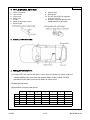
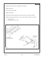
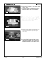
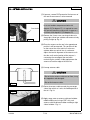
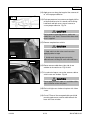
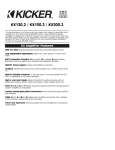
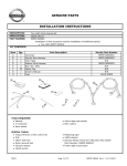
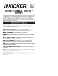
GENUINE PARTS
SATELLITE RADIO INSTALLATION INSTRUCTIONS
1. DESCRIPTION: SATELLITE RADIO SYSTEM
XM tuner kit
2. PART NUMBERS:
SIRIUS tuner kit
XM antenna kit
SIRIUS antenna kit
999U9-NV003
999U9-NV004
999U9-VQ006
999U9-VQ007
3. MODEL APPLICATION: Maxima (2004~ last 6 digits of VIN is 835089 or later)
4. TUNER KIT CONTENTS:
Parts View
No. Parts
Qty
1 Tuner
1
2
2 Black Tape
2
3 Velcro Tape (hook)
2
4 Velcro Tape (loop)
5 Double-Stick Foam Pad
1
6 L Bracket
2
7 M4 Machine Screw
4
4
8 5mm Tapping Screw
9 Ground Cable
1
1
10 6mm Tapping Screw
14
11 Sponge Tape
1
12 Edge Protector
4
13 Clear Tape
1
14 Corrugated Tube
15 Cable Tie
4
2
16 Butyl Gum
4
17 Cable Clamp
CAUTION
• This can be a difficult and time consuming installation that may require the skill of the master
technician who is familiar with electronics installation. Contact your regional DTS for additional
information on installation support.
• Tuner unit, antenna, and antenna splitter must be same brand, XM or SIRIUS
• This is a universal installation kit so all parts may not be used.
• Re-installation of satellite radio antenna to be performed by an authorized dealer only.
• In the event the satellite radio antenna or antenna splitter needs to be re-installed, do not use the
original mounting tape. Order the low profile antenna tape remount kit:
999U9-VQ010
• In the event the satellite radio antenna needs to be replaced, order the appropriate Satellite
Antenna Kit.
XM antenna
999U9-VQ012
SIRIUS antenna 999U9-VQ013
XM splitter
999U9-VQ004
SIRIUS splitter 999U9-VQ005
4.22.04
284-9798-00-L0
MAXIMA
5. TOOL & MATERIAL REQUIRED:
1. Phillips screwdriver
2. Tape measure
3. Clip remover
4. Soapy water
5. Flat file
6. 50/50-alcohol/water solution
7. Electrical tape
8. Adhesive tape
9. Masking tape
10. Drill with 4mm (5/32”) bit equipped
with1cm (1/2”) stop
11. Rustproof compound (Bitumen Wax,
999MP-9G001P or equivalent)
6. INSTALLATION OUTLINE:
7. VEHICLE PREPARATION:
(1) Using a PGF stick, confirm that there is not an excessive amount of sealant under rear
window molding at the area where the antenna cables will be installed. DO NOT
proceed to install radio if an excessive amount of sealant exists.
(2) Apply parking brake.
(3) Record the customer radio presets.
1
2
3
4
5
6
7
AM
AM2
FM1
FM2
FM3
ESN number located on tuner box:
4.22.04
2/13
284-9798-00-L0
MAXIMA
(4) Make sure that the shift lever is engaged in the "P" position.
(5) Open the trunk lid.
(6) Turn the ignition switch OFF
(7) Open engine hood.
(8) Disconnect the battery negative terminal to prevent short circuits during installation.
(9) Remove the following interior parts as shown in Fig. 1 (Refer to vehicle service manual)
• Trunk panel, RH
• Package tray lower trim cover
Trunk side
finisher, RH
Package Tray
Lower Trim Cover
clips
Fig. 1
4.22.04
3/13
284-9798-00-L0
MAXIMA
8. TUNER INSTALLATION:
(1) Attach two (2) L brackets to tuner with four (4) M4
screws. Fig. 2
(2) Cut two (2) 100mm by 30mm spacers from the
double stick spacer (item # 5 in kit contents).
Fig. 2
(3) Clean the back surface of the tuner with 50/50
alcohol/water solution. Attach the two (2) 100mm
by 30mm strips of double stick foam pad to
bottom of tuner as shown. Fig. 3
Fig. 3
(4) Remove protective backing from foam pads and
attach tuner to underside of package tray as
shown. Fig. 4
Fig. 4
4.22.04
(5) Use 4mm (5/32") drill bit to drill holes through
center hole on L brackets, and secure tuner to
package tray with two (2) 5mm tapping screws.
4/13
284-9798-00-L0
MAXIMA
Front of Vehicle
Fig. 5
(6) Insert antenna splitter cable connectors into
corresponding tuner terminals.
(7) Clean the tuner with 50/50 alcohol/water solution
where the splitter is to be attached.
NOTE
Ensure that the tuner surface is thoroughly
cleaned before proceeding.
(8) Peel off the tape protector from the splitter. Place
the splitter on tuner and secure in position by
applying force with hand pressure. Fig. 5.
Fig. 6
N-BUS
connector
(9) Remove the tear tape to release the prewired NBUS cable. Fig. 6
tear tape
Fig. 7
4.22.04
N-BUS
connector
(10) Connect N-Bus cable connector to the
corresponding tuner terminal. Fig. 7
5/13
284-9798-00-L0
MAXIMA
9. NOTCH CUTTING:
(1) Remove weather-strip from right side of trunk
opening.
Tape
Fig. 8
(2) Apply 150mm (6") of masking tape to the vertical
edge of the gutter as illustrated in Fig. 8
Gutter
Weld
seam
75mm
Mark
Fig. 9
(3) Measure 75mm (3") from weld seam at top right of
gutter to the rear right of vehicle and mark position
on masking tape with pen. Fig. 9 & 10
(4) Measure 15mm (5/8") from pen mark to rear of
vehicle and mark position on masking tape with
pen. Fig. 11
(5) Measure 3mm (1/8") down from top edge of gutter
lip and make a horizontal line connecting the two
(2) pen marks. This figure illustrates the area of
material that will be removed using the die grinder.
Fig. 11
Fig. 10
notch area
WARNING
3 mm
15 mm
Use eye protection.
CAUTION
Cut the notch
Fig. 11
Do not damage vehicle parts during notch cutting
procedure. Protect window and trim with fender
cover or similar.
(6) Cut the notch with die grinder and cut-off wheel.
(7) Remove masking tape.
(8) Remove burrs or sharp edges from the notch.
(9) Blow away metal chips and clean gutter and notch
with 50/50 alcohol/water solution.
(10) Apply rustproof compound to the cut surface of
the notch.
4.22.04
6/13
284-9798-00-L0
MAXIMA
10. ANTENNA INSTALLATION:
(1) If present, remove PGF protective film from rear of
the roof where antenna is to be mounted.
CAUTION
In case of ambient temperatures below 20
degrees C (70 degrees F), it is required to warm
the tape and mounting surface with a heater to a
minimum of 20 degrees C (70 degrees F).
Clip
points
Fig. 12
(2) Remove the 10mm screw securing window trim
along right side of rear window and remove trim by
pulling straight up. Fig. 12
(3) Place the antenna on the roof in the approximate
position it will be mounted. This position will be
on the center-line of the vehicle, use the rear
window defroster vertical line as a reference.
Adjust the fore/aft alignment of the antenna such
that the small vertical portion of the antenna is
contacting the rear edge of the roof while
maintaining the smallest visible gap between the
antenna tail and the edge of the roof line.
(4) Unwrap antenna cable.
CAUTION
• Do not let the antenna cable rest on floor; it may
be stepped on and damaged.
Fig. 13
Fig. 14
• Do not kink antenna cable.
(5) Route the antenna cable towards the passenger
side of the vehicle as it exits the flexible portion of
the tail. Fig. 13
(6) Apply soapy water to antenna cable and window
rubber molding and, using a PGF stick, tuck
antenna cable underneath rubber molding to right
side of window. Fig. 14
4.22.04
7/13
284-9798-00-L0
MAXIMA
Fig. 15
Metal window
frame
PGF Stick
NOTE
Insert the stick under the rubber molding. Twist it
to make room under the rubber molding. Place the
antenna cable under the rubber molding.
Reference Fig. 15
Rear
window Antenna
cable
Rubber
molding
PGF
Stick
Antenna
cable
(7) Cut out antenna and tail outline and two square
holes on antenna template. Fig. 16
(8) Carefully lift antenna from the roof, do not pull out
the wire that was just tucked, and clean the area
where the antenna is to be mounted with a 50/50
alcohol/water solution. Put antenna back on roof.
CAUTION
Do not touch or contaminate the cleaned roof or
adhesive tape on the antenna to prevent reduction
of adhesive strength.
Fig. 16
Fig. 17
(9) Align template to vehicle centerline at bottom of
template and the 2 square holes, and roof edge.
Affix to vehicle with masking tape. Use vertical
defroster line for vehicle centerline. Fig. 16
(10) Position antenna and tail in template and fine tune
alignment based on centerline of template.
Fig. 16
(11) Adjust the fore/aft position of antenna such that
antenna tail and roof have maximum contact
surface with minimum gap at edge of roofline. Fig.
16
(12) Peel tape protector from rear of the antenna tail
and lay down tail. Fig. 17
CAUTION
Antenna cable
4.22.04
Fig. 18
Make sure antenna cable remains vertical under
antenna tail flap. Fig. 18
8/13
284-9798-00-L0
MAXIMA
(13) Apply pressure along the length of the antenna tail
to ensure proper adhesion.
Fig. 19
(14) Peel tape protector from antenna and apply 20 lbs.
of downward force for 20 seconds while rocking
hand back and forth across top of antenna to
assure proper adhesion. Fig. 19
CAUTION
During antenna mounting process, make sure
rubber dust seal "flares" outward while downward
force is applied.
(15) Remove template from vehicle.
CAUTION
•
Keep vehicle inside at least one hour after
applying adhesive tape.
Fig. 20
•
Avoid works imposing pressure on the
adhered area including car wash within 48 hours.
Fig. 21
(16) Route antenna cable down right side of rear
window to the notch area. Fig. 20 & 21
(17) Use electrical tape to secure the antenna cable to
vehicle near rear window. Fig. 20
CAUTION
Do not apply too much tape as it could be visible
after installation of the trim piece.
(18) Re-install right rear window trim piece with 10mm
screw.
(19) Cut off 75mm of the corrugated tubing and slide
remaining piece over antenna cable towards the
base of the rear window.
4.22.04
9/13
284-9798-00-L0
MAXIMA
(20) Starting 1" from right hand lower corner of window
along wire affix four (4) cable clamps to gutter area
towards notch as shown. Final clamp should be
located as close to edge of gutter on the furthest
flat horizontal surface approximately 1" from notch.
Alternate the clamps while installing. Fig. 22
Clamps
CAUTION
•
Make sure corrugated tubing is far enough
away from gutter lip so it does not interfere with
Fig. 22
trunk weather strip.
•
Fig. 23
Do not affix cable clamp on sealant.
(21) Clean underside of the gutter, where clear tape
will be applied, with 50/50 alcohol/water solution
then apply clear tape to prevent abrasion as
shown. Fig. 23
NOTE
The following steps 22 to 28 are critical to water
leak, therefore must be followed strictly.
(22) Place the edge protector over the notch.
(23) Use Alcohol wipe included in the kit to clean the
surrounding area before application of clear tape.
(24) Route the antenna cable over the edge protector
by laying the cable into the channel in the rubber.
CAUTION
Make sure the antenna cable is seated in channel
on both sides of the edge protector.
(25) Position the clear tape above the notch without
peeling off the liner to estimate the correct position
for the small amount of butyl gum.
(26) Before applying the clear tape, apply a small
amount of butyl gum to bottom side of antenna
cable to hold the antenna cable at the radius
corner where it will enter the clear tape.
4.22.04
10/13
284-9798-00-L0
MAXIMA
Trunk area side
Gutter side
Fig. 24
(27) Do not peel off the entire clear tape protector. Pull
the clear tape protector back 10mm (3/8"). Then
apply 10mm clear tape to the horizontal flat
surface of the gutter. Then slowly massage the
clear tape with a PGF stick until you have reached
the corners. Make sure that the tape does not
wrinkle. Apply the same technique to the vertical
surface. Then fold the tape over and apply the
technique once more. This should leave a smooth
surface on all three sides. Fig. 24 & 25
CAUTION
• In order to stop water from entering the trunk
Fig. 25
through the clear tape, the clear tape must have
complete (100%) wet out 5 - 10mm (1/4" - 3/8")
on all three sides of peripheral boundary and no
wrinkles. Fig. 25
• Ensure antenna cable is entering the clear tape
at the radius corner.
clear tape
(28) Apply butyl gum at both ends of the clear tape.
The butyl gum should fit into both corners to cover
the antenna cable and opposite end of clear tape.
Fig. 24
Fig. 26
CAUTION
Butyl gum must be placed across the cable for
good water seal.
Fig. 27
(29) Apply clear tape over the two (2) panel joints as
illustrated to protect antenna cable. Fig. 26
Sponge
tape
(30) Route antenna cable to tuner/splitter location and
secure to package tray with four (4) pieces of
sponge tape. Fig. 27 & 28
Fig. 28
4.22.04
11/13
284-9798-00-L0
MAXIMA
(31) Leaving enough length for the splitter connection,
neatly coil excess antenna cable to create a loop
100mm (4") in diameter.
CAUTION
Fig. 29
• Do not kink the antenna cable.
• Do not change diameter of the antenna loop.
Sponge tape
(32) Insert antenna terminal into corresponding splitter
terminal. Fig. 29
Fig. 30
Sponge tape
Fig. 31
loop
(33) Working from the tuner back towards the notch
secure the antenna cable to the existing harness
and/or to vehicle interior trunk surfaces with five
(5) pieces of sponge tape. Fig. 30 & 31
(34) Secure antenna loop to interior trunk panel with
two (2) pieces of sponge tape. Fig. 31
4.22.04
12/13
284-9798-00-L0
MAXIMA
11. OPERATION CHECK
(1) Connect the battery negative terminal.
(2) Turn vehicle ignition switch to the "ACC" position.
(3) Turn radio on then select satellite radio mode. Acquiring (Sirius) or loading (XM) will display
for a while. If not, move vehicle to outside and try again.
(4) Tune to preview channel (XM: channel "1" / SIRIUS: channel "184") to make sure receiving
preview channel correctly.
(5) Confirm proper audio operation. (AM / FM / TAPE / CD)
12. REINSTALLATION OF REMOVED PARTS
(1) Re-install all removed vehicle parts referring to the service manual for the vehicle.
(2) Clean interior of vehicle.
13. FINAL INSPECTION
(1) Inspect the vehicle interior and exterior for damage.
(2) Confirm proper operation of vehicle systems including moonroof if equipped.
(3) Reset radio presets to the recorded settings.
(4) If equipped reset the moonroof per service manual requirement.
4.22.04
13/13
284-9798-00-L0