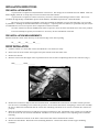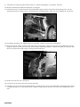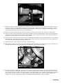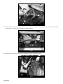
1
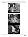
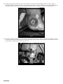
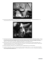
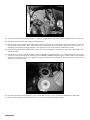
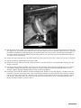
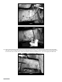
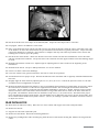
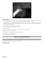
491 W. Garfield Ave., Coldwater, MI 49036
Phone: 517-279-2135
Web/live chat: www.bds-suspension.com
E-mail: [email protected]
Part#:022410
Product: 4" Suspension System
Application: 2002-2005 Dodge Ram 1500 4wd
Read and understand all instructions and warnings prior
to installation of system and operation of vehicle.
SAFETY WARNING BDS Suspension Co. recommends this system be installed by a professional technician. In
addition to these instructions, professional knowledge of disassembly/ reassembly procedures and post installation
checks must be known.
PRODUCT SAFETY WARNING
Certain BDS Suspension products are intended to improve off-road performance. Modifying your vehicle for off-road use may result in the vehicle handling differently than a factory equipped
vehicle. Extreme care must be used to prevent loss of control or vehicle rollover. Failure to drive your modified vehicle
safely may result in serious injury or death. BDS Suspension Co. does not recommend the combined use of suspension
lifts, body lifts, or other lifting devices.
You should never operate your modified vehicle under the influence of alcohol or drugs. Always drive your modified vehicle at reduced speeds to ensure your ability to control your vehicle under all driving conditions. Always wear your seat
belt.
Pre-Installation Notes
1. Special literature required: OE Service Manual for model/year of vehicle. Refer to manual for proper disassembly/
reassembly procedures of OE and related components.
2. Adhere to recommendations when replacement fasteners, retainers and keepers are called out in the OE manual.
3. Larger rim and tire combinations may increase leverage on suspension, steering, and related components. When
selecting combinations larger than OE, consider the additional stress you could be inducing on the OE and related
components.
4. Post suspension system vehicles may experience drive line vibrations. Angles may require tuning, slider on shaft
may require replacement, shafts may need to be lengthened or trued, and U-joints may need to be replaced.
5. Secure and properly block vehicle prior to installation of BDS Suspension components. Always wear safety glasses
when using power tools.
6. If installation is to be performed without a hoist, BDS Suspension Co. recommends rear alterations first.
7. Due to payload options and initial ride height variances, the amount of lift is a base figure. Final ride height
dimensions may vary in accordance to original vehicle attitude. Always measure the attitude prior to beginning
installation.
POST-INSTALLATION WARNINGS
1. Check all fasteners for proper torque. Check to ensure for adequate clearance between all rotating, mobile, fixed, and
heated members. Verify clearance between exhaust and brake lines, fuel lines, fuel tank, floor boards and wiring
harness. Check steering gear for clearance. Test and inspect brake system.
2. Perform steering sweep to ensure front brake hoses have adequate slack and do not contact any rotating, mobile
or heated members. Inspect rear brake hoses at full extension for adequate slack. Failure to perform hose check/
replacement may result in component failure. Longer replacement hoses, if needed can be purchased from a local
parts supplier.
3. Perform head light check and adjustment.
4. Re-torque all fasteners after 500 miles. Always inspect fasteners and components during routine servicing.
rev. 3/3/2014
022410 Page 1
PARTS LIST
Part #
Qty Description
02230
1
Steering Knuckle (drv)
02231
1
Steering Knuckle (pass)
44016
2
Tie Rod Ends (18mm 02-05)
02270
1
Front Crossmember - HC
02271
1
Rear Crossmember -HC
3527RB 4Bushing
112
2Sleeve
113
2
Large dia washers
516
2
Grease zerk - straight
02289
1
Torsion Bar Bracket (drv)
02290
1
Torsion Bar Bracket (pass)
02274
2
Torsion Bar Brkt Spacer
02268
2
Front Bump Stop Bracket
M02060RB 2
Bump Stops - Blue
02269
1
Crossmember Brace
02276
1
Differential Skid Plate
911114
2
Sway Bar Link Extension
01240
1
Front Driveshaft Spacer
01234
1
Differential Brkt (pass)
01236
1
Differential Brkt (drv)
1
Differential Brkt (pass)
01237
01238
1
Differential Brkt
654
1
Bolt Pack
2
10mm-1.50 x 65mm bolt
Page 2 022410
617
778
779
loctite
1
Bolt Pack - Differential Drop
4
1/2"-13 x 2-3/4" bolt
7
1/2"-13 x 2-1/2" bolt
11
1/2"-13 prevailing torque nut
25
1/2" SAE flat washer
3
12mm-1.75 x 30mm bolt
1
Bolt pack - Main hardware
2
5/8"-11 x 5-1/2" bolt
2
5/8"-11 x 8" bolt
4
5/8"-11 prevailing torque nut
8
5/8" SAE flat washer
4
1/2"-13 x 3" Button head bolt
4
1/2"-13 prevailing torque nut
6
1/2"-13 x 1-1/4" bolt
2
1/2"-13 x 1-3/4" bolt
12
1/2" SAE washer
2
1/2"-13 flanged nut
1
Bolt pack - Front Driveshaft - misc.
4
12mm-1.75 x 45mm bolt
4
12mm flat washer
2
3/8"-16 x 1-1/4" SHCS
2
3/8" SAE Flat washer
2
5/16"-18 x 1-1/4" self tapping bolt
1loctite
INSTALLATION INSTRUCTIONS
PRE-INSTALLATION NOTES
-
A special tool is required to load/unload the torsion bars. The Dodge service manual lists tool #8686. This tool
differs slightly from the C-clamp style tool used on most other IFS vehicles.
A special tool is required to remove the factory rear lower control arm bushings from the frame. This tool is
-
available through Dodge or SPX-Miller Special Tools (#8682). SPX-Miller Special Tool- 1-800-801-5420.
The factory service manual specifically states that striking the knuckle to loosen the ball joints or tie rod ends
-
is prohibited. Striking the aluminum knuckle can damage it. A special puller tool #8677 (or equivalent ball joint tool) is
recommended to be used to separate these components from the knuckle.
-
On some vehicles an exhaust modification will be required to clear the front driveshaft in its new, lower position.
-
T-60 and T-55 impact quality torx sockets are necessary for the installation of this kit.
PRE-INSTALLATION MEASUREMENTS
Measure from the center of the wheel up to the bottom edge of the wheel opening
LF______ RF______ LR______ RR______
FRONT INSTALLATION
1. Park the vehicle on a clean, flat surface and block the rear wheels for safety.
2. Raise the front of the vehicle and support with jack stands under the frame rails.
3. Remove the wheels.
4. Measure and record the length of the exposed thread on the torsion bar adjusting bolts for later reference (Fig 1).
DRV__________ PASS__________
Fig 1
5. Remove the torsion bar adjuster bolt and retainer block. CAUTION: The torsion bars are under extreme pressure.
Use the correct unloading tool to remove the pressure on the torsion bars before attempting to remove the assembly.
Be sure to follow the OE manual and the torsion bar unloading tool literature as to how to unload the torsion bars
properly.
6. Mark the unloaded torsion bars to indicate passenger’s and driver’s side. Mark both of the torsion bars to indicate
the front verses the rear for later installation. Mark the rear of the bars relative to the adjusting arms to indicate
indexing.
7. Pull the torsion bars back out of the lower control arms and remove them from the vehicle.
8. Remove the OE shocks. Retain the lower mounting hardware. Discard the shock and the upper mounting
hardware.
022410 Page 3
9. Disconnect the sway bar links from the sway bar. Retain all bushings, cup washers, and nuts.
10. Remove and discard the OE front skid plate, if equipped.
11. Disconnect the tie rod ends from the steering knuckles (Fig 2). Remove and retain the mounting nuts. Use the
appropriate puller to separate the tie rod end from the steering knuckle. Take care not to damage the tie rod end.
Fig 2
12. If equipped, disconnect the ABS brake line at the frame. Remove it from any retaining clips.
13. Remove the brake caliper anchor bracket bolts (Fig 3) and pull the caliper free from the steering knuckle and rotor.
Hang the caliper securely out of the way. Retain caliper mounting hardware. Remove the brake rotor from the hub.
Note: Do not allow the brake caliper to hang from the brake hose.
Fig 3
14. Remove the hub axle nut. Retain nut.
15. Loosen but do not remove the lower control arm bolts.
16. Disconnect the CV axles from the differential by carefully prying CV out at the differential to disengage the internal
retaining clip (Fig 4). Pry the shaft out just enough to release the clip and leave the axle on the differential at this
time.
Page 4 022410
Fig 4
17. Remove the upper and lower ball joint nuts. Reinstall the nuts a few turns by hand. Separate the upper and lower
ball joints from the steering knuckle using the appropriate puller. Take care not to damage the ball joint. Remove
the upper ball joint nut and allow the knuckle/CV axle and lower control arm to swing down while sliding the CV
axle off of the differential. Remove the CV axle from hub.
18. Remove the lower ball joint nut and remove the knuckle from the lower control arm. Retain the ball joint nuts.
19. Remove the three bolts mounting the hub bearing assembly to the OE steering knuckle. Retain the mounting bolts.
Remove the hub assembly and dust shield from the knuckle. Note: It may be necessary to press the hub out of the
knuckle as a result of excessive corrosion on some vehicles.
20. Install the hubs and factory dust shield on the corresponding new knuckles (01230, 01231) and fasten with the stock
mounting bolts. Index the hub so that the ABS line runs out the front side of the knuckle toward the steering arm.
Use Loctite on the bolt threads and torque to 125 ft-lbs.
21. Remove the lower control arms from the frame. Retain hardware.
22. Make indexing marks on the front drive shaft and differential input flange for realignment later (Fig 5). Remove the
four bolts and disconnect the drive shaft from the differential. Discard mounting bolts.
Fig 5
23. Locate the exhaust crossover pipe. If the crossover pipe runs under the front driveshaft it must be modified (Fig 6).
The pipe can either be completely removed or cut to clear the driveshaft at this time. The other option is to wire up
the front drive shaft if traveling a very short distance to the exhaust shop. Note: Vehicles equipped with a crossover
pipe that runs near the transfer case will not require an exhaust modification. Have the exhaust modifications
completed by a quality exhaust shop when the installation of this suspension system is complete.
022410 Page 5
Fig 6
24. Remove the four bolts mounting the OE rear crossmember to the frame rails and remove the crossmember from the
vehicle (Fig 7). Discard the crossmember and the hardware.
Fig 7
25. Disconnect the vent hose and wiring (if equipped) from the differential (Fig 8).
Fig 8
Page 6 022410
26. Using a jack, support the differential. Loosen and remove the two forward-most differential mounting bolts on the
driver’s side (Fig 9). Loosen but do not remove the three rear driver’s side bolts (Fig 10) and the two passenger’s side
bolts (Fig 11).
Fig 9
Fig 10
Fig 11
27. With the differential securely supported, remove the remaining bolts and lower the differential from the vehicle.
022410 Page 7
28. Using the appropriate puller tool, press out the OE rear lower control arm bushings from the frame. Refer to
individual puller tool instructions for proper operating procedures. Another option is to cut the OE bushing flush
with the backside of the frame. This is needed for clearance of the torsion bar relocation brackets (Fig 12).
Fig 12
29. The lower control arm bump stop cups must be removed from the frame. Using a saw-zall or cutoff wheel, cut the
weld beads holding the bump stop cups to the frame (Fig 13 A/B). Remove the cups and be sure that the surface is
ground flush. Paint any bare metal to prevent rust.
Fig 13a
Page 8 022410
Fig 13b
30. Install the provided passenger’s side differential drop bracket (01234) to the original frame mount with two ½” x
2-3/4” bolts, nuts and ½” SAE washers (BP #617). Leave hardware loose (Fig 14).
Fig 14
31. Install the two front driver’s side differential drop brackets so that the bracket with the small offset (01236) is toward
the outside of the vehicle (offsetting out) and the one with the bigger offset (01237) is on the inside (offsetting in). The
brackets should taper down in height as they go toward the rear of the vehicle. Fasten the brackets to the frame
with two ½” x 2-1/2” bolts, nuts and ½” SAE washers (BP #617). Leave hardware loose.
32. Install the driver’s side rear differential drop bracket (01238) to the frame with three 12mm x 30mm bolts and ½”
SAE washers (BP #617) into the existing welded nuts on the frame. The bracket will offset toward the outside of the
vehicle with the gusset to the front. Leave hardware loose.
33. Using a jack (and an assistant to aid in balancing) raise the differential up to the new brackets.
34.Attach the differential to the driver’s side front and rear brackets (Fig 15) with ½” x 2-1/2” bolts, nuts and washers
(BP #617). Attach the passenger’s side to the differential with ½” x 2-3/4” bolts, nuts and ½” SAE washers (BP #617).
Leave all differential hardware loose.
022410 Page 9
Fig 15
35. Torque all 14 differential mounting bolts. Torque the ½” hardware to 65 ft-lbs and the 12mm hardware to 50 ft-lbs.
36. Attach the breather hose and wiring to the differential.
37. Install the new front crossmember (02270) in the OE front lower control arm pockets and loosely fasten with the OE
lower control arm hardware. Note: The offset in the crossmember goes to the front, bolts run from front to rear. If
installing optional dual steering stabilizers, the tips must be cut off the bolts for additional clearance.
38. Grease and install new bushings and sleeve into the rear crossmember. Install grease zerks into crossmember and
tighten securely.
39. Install the new rear crossmember (02271). The crossmember is attached with ½” x 3” button head bolts. Do not put
a washer on the head of the bolt. Run the bolt from REAR to FRONT and attach with ½” SAE washer and Prevailing
Torque Nut. It may be necessary to slightly clearance the holes in the frame for the larger than factory bolts, do not
tighten at this time (Fig 16).
Fig 16
40.Install the new differential skid plate to the crossmembers with ½” x 1-1/4” bolts and SAE washers (BP #618).
41. Install the passenger’s side skid plate with ½” x 1-1/4” bolts and SAE washers (Fig 17).
Page 10 022410
Fig 17
42. Install the provided hexagon shaped urethane bump stops to the new bump stop extensions (02268).
43. Attach the bump stop extension to the frame with 3/8” x 1-1/4” socket head cap bolts and 3/8” SAE washers down
through the original bump stop frame mount (Use loctite on the threads). Use a rag to protect the powdercoat if a
wrench is used on the bumpstop (Fig 18). Note: Bumpstop included in the kit has a lower profile than shown in the
picture below.
Fig 18
44.Mark the control arm as shown. This area must be removed from the control arm for CV boot clearance. The area
to be removed is wedge shaped. Draw a triangle to connect the points, and remove material with a grinder. Coat
with paint after material is removed (Fig 19a, b).
022410 Page 11
Align with
bottom of slot
Align with edge
3/4"
Fig 19a
Fig 19b
45. Remove corrosion inside the lower control arm where the bolt head originally rested. Install the spacer as shown
(Fig 20a, b).
Fig 20a
Page 12 022410
Fig 20b
46.Install the torsion relocation brackets on the arm as shown. Rotate the arm so that the flat bracket rests on the
control arm. Mark the hole center and drill to ½”. Attach with ½” x 1-3/4” bolt with washer on the head of the
bolt, and a serrated flanged nut on the inside of the control arm. Use loctite on the threads and tighten to 65 ft-lbs
(Fig 21).
Drill 1/2"
Fig 21
47. Install the lower control arms in the front and rear crossmembers. Attach the control arms to the front
crossmember with 5/8” x 5-1/2” bolts, nuts and 5/8” SAE washers (BP #778) (installed from front to back). Install
the spacer washer as shown, attach the arms to the rear crossmember with 5/8” x 8” bolts, nuts, and 5/8” SAE
washers (installed from front to back) (Fig 22a, b).
022410 Page 13
Front
113 Large
Washer
Fig 22a
Fig 22b
48.With the lower control arms installed, torque the crossmember hardware as follows: Front crossmember- upper OE
bolts 125 ft-lbs; Rear crossmember- 1/2” button head hardware 65 ft-lbs. Leave control arms loose.
49. Torque the differential skid plate hardware to 65 ft-lbs.
50. Install the provided drive shaft spacer on the differential input flange. Attach the front driveshaft to the differential
by aligning the marks made earlier. Fasten the driveshaft and spacer to the differential flange with 12mm x 45mm
bolts and 12mm washers (BP#779). Use loctite on the bolt threads and torque to 55 ft-lbs (Fig 23).
Page 14 022410
Fig 23
51. Install the new driver’s side steering knuckle to the driver’s side lower control arm ball joint and loosely attach with
the original nut. Install the driver’s side CV axle in the hub and loosely fasten with the original axle nut. Swing the
knuckle/CV assembly up while aligning the axle with the differential output shaft. Loosely attach the knuckle to
the upper control arm ball joint with the original nut. Push the CV axle all the way onto the differential output to
seat the internal retaining clip.
52. Torque the upper ball joint nut to 55 ft-lbs and the lower ball joint nut to 60 ft-lbs. Torque the axle nut to 185 ft-lbs.
53. Repeat knuckle/CV installation on passenger’s side.
54.Remove the factory outter tie rod end. Attach the new tie rod ends to the new steering knuckles with the new nut.
Torque to 45 ft-lbs.
55. Install the sway bar link extensions onto the factory sway bar links, tighten securely. Install factory cup washers
and rubber bushings onto sway bar links. Attach to sway bar with new 10mm bolt (BP# 654) with loc-tite on
threads. Tighten until the bushings begin to swell – Do NOT overtighten.
56. Passenger’s side brake line: Remove the bolt retaining the line bracket to the frame (Fig 24). Carefully reform the
hard line so that the mounting bracket can be lowered approximately 3” (remove the hard line from the retaining
clip on the inside of the frame rail). Measure back ½” from the lower existing hole in the frame and drill a 17/64”
hole (Fig 25). Attach the brake line to the new hole with the provided 5/16” x 1-1/4” self-tapping bolt (BP #779).
Ensure that the hard line is properly routed.
022410 Page 15
Fig 24
Fig 25
57. Driver’s side brake line: Remove the bolt retaining the line bracket to the frame (Fig 26). Support the hard leader
with pliers and carefully bend the line down approximately 30º (Fig 27). Mark and drill the new mounting location
on the frame with a 17/64” drill. Fasten the bracket with the provided 5/16” x 1-1/4” self-tapping bolt (BP #779).
Fig 26
Page 16 022410
Fig 27
58. Install the brake rotor and caliper on the knuckle/hub. Torque the OE caliper bolts to 130 ft-lbs.
59. If equipped, connect the ABS wire at the frame.
60.Place a jack under the lower control arm and raise the arm until the distance from the center of the hub to the edge
of the fender is 6” more than measured in the pre-installation measurements (typically about 28”). Torque the lower
control arm hardware to 125 ft-lbs. Note: Failure to complete this step will result in premature lower control arm
bushing wear as well as poor ride quality.
61. Install the new front shocks. Attach the shocks to the lower control arm with the OE hardware and to the frame
with the provided new hardware. Torque the lower bolt to 95 ft-lbs and the upper hardware until the bushings begin
to swell.
62. Reinstall and load the torsion bars. Adjust length of adjusting bolts to that recorded at the beginning of the
installation.
63. Reinstall front wheels. Torque to OE specifications, see owner’s manual.
64.Grease rear lower control arm bushings.
65. Lower the vehicle to the ground and bounce the front to settle the suspension.
66.Check all fasteners for proper torque. Recheck all fasteners after 500 miles and at regularly scheduled maintenance
intervals.
67. Roughly align the front wheels by adjusting the toe to 1/16"~1/8" toe-in. Lock off the jam nuts on the tie rod ends.
A complete front end alignment is required.
68.Recheck the final lift height and compare to the pre-installation measurements recorded earlier. If necessary, adjust
the torsion bars to achieve 4" of lift over the original measurements. The front height measurement should not
exceed 27". If your vehicle is equipped with aftermarket fenderflares, check the ‘z’ height. Measure and record the
distance from the center of the lower control arm bolt to the ground and from the center of the lower shock bolt to
the ground. The difference between the two should be nealy zero (+/- 1/2") (arm is level). This will ensure proper
front end alignment and good ride quality. The ride height can be adjusted in the front to get the desired rake, since
these trucks came from the factory with a stance 1-1/2"~3-1/2" tail high. Optional rear blocks can also be ordered
to adjust rear stance.
Rear Installation
69. Block the front wheels for safety. Raise the rear of the vehicle and support the frame with jack stands.
70. Remove the wheels.
71. Support the axle with a hydraulic jack.
72. Remove the OE shocks. Retain the mounting hardware.
73. Remove the parking brake cable retaining ring from the driver’s side frame rail (Fig 28). Remove the ring from the
cables.
022410 Page 17
Fig 28
Block Installation
74. Remove the passenger’s side u-bolts. Lower the axle from the leaf spring enough to install the provided 2” lift block.
Note: Take care not to over-extend any wires or hoses. Make adjustments where necessary.
75. Install the 2” block so that the short end of the block is toward the front of the vehicle. Fasten the spring, block and
axle together with the provided u-bolts, high nuts and washers. Snug u-bolts. The final u-bolt torque is performed
with the vehicle on the ground.
76. Repeat installation on the driver’s side of the vehicle.
77. Install the new BDS shocks with the OE hardware.
78. Install the wheels.
79. Lower the vehicle to the ground and bounce the vehicle to settle the suspension.
80. Torque the u-bolts to 100-120 ft-lbs.
81. If installing new rear springs, torque spring bolts to 95 ft-lbs.
82. Check all hardware for proper torque.
83. Check all hardware after 500 miles.
Notice to Dealer/Installer
These instructions, the warning card, and included decals must be given to the owner of this BDS Suspension product.
For questions, technical support and warranty issues relating to this BDS Suspension product, please contact your distributor/installer before contacting BDS Suspension directly.
Sold/Installed by:
Page 18 022410