1
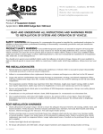
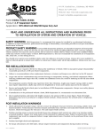
491 W. Garfield Ave., Coldwater, MI 49036
Phone: 517-279-2135
Web/live chat: www.bds-suspension.com
E-mail: [email protected]
Part#: 023602, 023604
Product: 6" Suspension System
Application: 1997-2003 Ford F-150 4wd, 1998-2002 Ford Expedition 4wd (Front Only)
Read and understand all instructions and warnings prior
to installation of system and operation of vehicle.
SAFETY WARNING
BDS Suspension Co. recommends this system be installed by a professional technician.
In addition to these instructions, professional knowledge of disassembly/ reassembly procedures and post installation
checks must be known.
PRODUCT SAFETY WARNING
Certain BDS Suspension products are intended to improve off-road performance. Modifying your vehicle for off-road use may result in the vehicle handling differently than a factory equipped
vehicle. Extreme care must be used to prevent loss of control or vehicle rollover. Failure to drive your modified vehicle
safely may result in serious injury or death. BDS Suspension Co. does not recommend the combined use of suspension
lifts, body lifts, or other lifting devices.
You should never operate your modified vehicle under the influence of alcohol or drugs. Always drive your modified vehicle at reduced speeds to ensure your ability to control your vehicle under all driving conditions. Always wear your seat
belt.
Pre-Installation Notes
1. Special literature required: OE Service Manual for model/year of vehicle. Refer to manual for proper disassembly/
reassembly procedures of OE and related components.
2. Adhere to recommendations when replacement fasteners, retainers and keepers are called out in the OE manual.
3. Larger rim and tire combinations may increase leverage on suspension, steering, and related components. When
selecting combinations larger than OE, consider the additional stress you could be inducing on the OE and related
components.
4. Post suspension system vehicles may experience drive line vibrations. Angles may require tuning, slider on shaft
may require replacement, shafts may need to be lengthened or trued, and U-joints may need to be replaced.
5. Secure and properly block vehicle prior to installation of BDS Suspension components. Always wear safety glasses
when using power tools.
6. If installation is to be performed without a hoist, BDS Suspension Co. recommends rear alterations first.
7. Due to payload options and initial ride height variances, the amount of lift is a base figure. Final ride height
dimensions may vary in accordance to original vehicle attitude. Always measure the attitude prior to beginning
installation.
POST-INSTALLATION WARNINGS
1. Check all fasteners for proper torque. Check to ensure for adequate clearance between all rotating, mobile, fixed, and
heated members. Verify clearance between exhaust and brake lines, fuel lines, fuel tank, floor boards and wiring
harness. Check steering gear for clearance. Test and inspect brake system.
2. Perform steering sweep to ensure front brake hoses have adequate slack and do not contact any rotating, mobile
or heated members. Inspect rear brake hoses at full extension for adequate slack. Failure to perform hose check/
replacement may result in component failure. Longer replacement hoses, if needed can be purchased from a local
parts supplier.
3. Perform head light check and adjustment.
4. Re-torque all fasteners after 500 miles. Always inspect fasteners and components during routine servicing.
rev. 5/1/2013
023600, 023601, 023602, 023603 Page 1
PARTS LIST
536
Part #
Qty Description
01070
01071
534
1
1
1
4
4
8
1
3
3
12
18
5
1
1
5
2
2
2
2
2
2
1
2
2
4
2
1
2
2
535
580
422
Steering Knuckle (drv)
Steering Knuckle (pass)
Bolt Pack
5/8”-11 x 5-1/2” bolt grade 8
5/8”-11 prevailing torque nut
5/8” SAE flat washer
Bolt Pack
12mm-1.75 x 100mm bolt grade 10.9
12mm-1.75 prevailing torque nut
12mm-1.75 x 45mm bolt grade 10.9
12mm flat washer
1/2”-13 x 1-1/4” bolt grade 8
1/2”-13 prevailing torque nut
1/2” USS flat washer
1/2” SAE flat washer
1/4”-20 x 3/4” bolt grade 5
1/4” SAE flat washer
1/4” split lock washer
wire clip
1/4” SAE flat washer
1/4” split lock washer
Bolt Pack - Bump Stops
7/16"-14 x 1-1/4" bolt grade 5
7/16"-14 prevailing torque nut
3/8" USS flat washer
3/8"-16 x 1-1/4" self-tapping bolt
Bolt Pack
1/4”-20 prevailing torque nut
1/4” SAE flat washer
Page 2 023600, 023601, 023602, 023603
1
Bolt Pack
4
7/16”-14 prevailing torque nut
4
7/16”-14 x 1-1/4” bolt grade 8
8
7/16” SAE flat washer
2
1/2”-13 x 1-1/4” bolt grade 8
2
1/2”-13 prevailing torque nut
4
1/2” SAE flat washer
01072
1
Front Crossmember
01073
1
Rear Crossmember
01074
1
Differential Drop Bracket
01075
1
Differential Skid Plate
01076
2
CV Spacer
01079
2
Torsion Bar Drop Bracket
01080
2
Bump Stop
87385
1
Alignment Cam Kit
01602
2
Brake Line Drop Bracket
02102
2
Sway Bar Link Bracket
911109
2
Sway Bar Link
SB35BK2 Bushing
SB26BK
4
Stem Bushing
S10076
4
Stem Washer
54587
2
Steel Sleeve
569
1
Bolt Pack
2
3/8"-16 nylock nut
2
7/16"-14 nylock nut
2
9/16"-12 x 2-3/4" bolt
4
9/16" SAE washer
2
9/16"-12 prevailing torque nut
2
5/8"-11 x 1-3/4" bolt
4
5/8" SAE washer
2
5/8"-11 nylock nut
342701 2Loctite
PRE-INSTALLATION MEASUREMENTS
Measure from the center of the wheel up to the bottom edge of the wheel opening
LF_______ RF_______ LR_______ RR_______
Front Installation
1. Park the vehicle on a clean, level surface and block the rear wheels for safety.
2. Safely raise the front of vehicle and support with jack stands for safety.
3. Remove the wheels.
4. Measure and record the length of the exposed thread on the torsion bar adjusting bolts for later reference.
DRV__________ PASS__________
CAUTION: The torsion bar is under extreme pressure. Use the correct unloading tool to remove the pressure on the torsion
bars before attempting to remove the assembly. A J36202 or equivalent torsion bar unloading tool must be used. Be sure
to follow the OE manual and the torsion bar unloading tool literature as to how to unload the torsion bars.
5. Unload the torsion bars, but do not remove.
6. Mark the unloaded torsion bars to indicate passenger’s and driver’s side. Mark both of the torsion bars to indicate
the front verses the rear for later installation. Also mark the torsion bars relative to the control arms at the front to
note indexing. Mark the rear of the bars relative to the adjusting arms to indicate indexing.
7. Remove the torsion bars by first removing the adjusting bolts then remove the retaining plates.
8. Drive the torsion bars forward using a maul or an air hammer through the access hole in the back of the torsion bar
crossmember. Note: This will allow the torsion bar adjusters to drop free.
9. Remove the bolts holding the torsion bar crossmember to the frame. Retain these fasteners with the crossmember
after removal. Remove the crossmember. Note: It may be necessary to remove a portion of the exhaust system on
some vehicles in order to complete this operation.
10. Remove the torsion bars by pulling them toward the rear of the vehicle.
11. If equipped, remove the transfer case skid plate by removing the two retaining bolts on each frame rail. Retain the
skid plate and hardware.
12. Remove the sway bar end links from the sway bar and lower control arms. Discard the end links.
13. Remove the shocks. Discard the shocks and retain the mounting hardware.
14. Disconnect the tie rod ends from the steering knuckles. Remove and retain the mounting nuts. Strike the steering
knuckle at the tie rod end to dislodge the end (Fig 1). Take care not to damage the tie rod end.
Fig 1
15. Disconnect the ABS brake wire from the frame and the control arm. Remove the brake hose bracket from the
steering knuckle.
023600, 023601, 023602, 023603 Page 3
16. Follow the ABS line up to the inner fender to find the wire connector. Disconnect the ABS wire and hang it out of the
way.
17. Disconnect the brake line bracket from the frame by removing the retaining bolt. Retain the mounting hardware.
18. Remove the brake caliper anchor bracket bolts and pull the caliper free from the steering knuckle and rotor (Fig 2).
Hang the caliper securely out of the way. Remove the brake rotor from the hub.
Fig 2
19. Remove the cotter pin, axle nut retainer and axle nut (Fig 3). Remove the brake dust shield.
Fig 3
20. Remove the upper and lower ball joint cotter pins and nuts. Reinstall the nuts a few turns by hand. Dislodge the
upper and lower ball joints from the steering knuckle by striking the knuckle near each joint with a hammer (Fig 4).
Remove the ball joint nuts and remove the knuckle from the vehicle. Retain the ball joint nuts.
Page 4 023600, 023601, 023602, 023603
Fig 4
21. Remove the three bolts mounting the hub bearing assembly to the steering knuckle (Fig 5). Retain the mounting
bolts. Remove the hub assembly from the knuckle. Note: It may be necessary to press the hub out of the knuckle as
a result of excessive corrosion on some vehicles.
Fig 5
22. Remove the six bolts retaining the CV shaft to the differential and remove the CV shaft from the vehicle (Fig 6).
23. Remove the lower control arm pivot bolts and remove the control arm from the vehicle.
Fig 6
023600, 023601, 023602, 023603 Page 5
24. Install the provided upper control arm eccentric cam washers and D-bolts on each side of the upper control arm
pockets. The perforated blank must be removed to change the pocket mounting holes to slots. Set the cams to the
middle of the eccentric slot. Snug but do not completely tighten the cam bolts.
25. Loosen but do not remove the two driver’s side and one passenger’s side differential mounting bolts (Fig 7, 8).
Fig 7
Fig 8
26. Install the new BDS rear crossmember into the stock rear lower control arm pockets and fasten with the OE bolts
and nuts. Do not tighten at this time. Note: The new crossmembers will fit relatively tight in the OE pockets.
27. Locate the new bump stop extensions (01080). Attach the bump stops to the back side of the mount tabs coming off
of the rear crossmember. When mounted, the holes in the bump stop ends should be toward the rear of the vehicle.
Attach the bump stops with 7/16" x 1-1/4" bolts, nuts and washers (BP 580). Snug hardware so that the bump stop
tab is flush against the crossmember tab but the bump stop can still be moved. (Fig 9A)
Page 6 023600, 023601, 023602, 023603
Fig 9A
28. Swing the bump stop extension up to the original frame bump stop location. Position the bump stop extension so
it is flat against the original and mark the mount hole to be drilled (Fig 9B). Swing the bump stop down and drill a
5/16" hole at the mark. Reposition the bump stop and attach with the provided 3/8" x 1-1/4" self-tapping bolt. Use
Loctite on the 3/8" bolt and torque to 20 ft-lbs. Torque 7/16" hardware at the crossmember to 45 ft-lbs.
Fig 9B
29. Install the new BDS front crossmember into the stock front lower control arm pockets and fasten with the OE pivot
bolts and nuts. Do not tighten at this time.
30. With the new crossmembers in place, remove the four OE rear crossmember bolts, driver’s rear differential bolt and
OE crossmember from the vehicle.
31. Remove the two remaining differential mounting bolts and lower the differential into the new front and rear
crossmembers (Fig 10A). Fasten the differential to the crossmembers on the driver’s side with 12mm x 100mm bolts,
nuts, and 12mm washers from bolt pack #535. Do not tighten.
023600, 023601, 023602, 023603 Page 7
Fig 10A
32. Mount the new passenger’s side differential drop bracket in the OE pocket with the long mounting tab pointing
toward the rear of the vehicle. Fasten the bracket to the OE pocket using the stock hardware (Fig 10B). Do not
tighten
Fig 10B
33. Attach the differential to the new drop bracket with a 12mm x 100mm bolt, nut and 12mm washers from bolt pack
#535. Do not tighten
34.Attach the tab of the drop bracket to the back of the control arm pocket with a ½” x 1-1/4” bolt, nut, ½” SAE and ½”
USS washer from bolt pack #535. Use the large USS washer on the outside surface of the control arm pocket. Do not
tighten at this time.
35. With all of the differential bolts installed go back and tighten the 12mm hardware to 60 ft-lbs. Tighten the ½” bolt to
60 ft-lbs.
36. Install the differential skid plate to the front and rear crossmembers with four ½” x 1-1/4” bolts and ½” SAE washers
(bolt pack #535) in the welded nuts in each crossmember. The front attachment points are accessed through the
slots in the crossmember. Do not tighten.
37. Install the driver’s and passenger’s lower control arms into the new crossmembers and fasten using 5/8” x 5-1/2”
bolts, nuts and washers from bolt pack #534. Do not tighten at this time.
38. Torque the four OE control arm pocket bolts to 125 ft-lbs. Torque the four skid plate bolts to 60 ft-lbs.
39. Install a new seal hub seal in the new BDS steering knuckles. Note: The old seals from the OE knuckles can be
removed and reused in the new knuckles. BDS highly recommends purchasing new seals from your local Ford
dealership.
40. Inspect the outer hub assembly mounting surfaces and clean any dirt or corrosion off as necessary. Install the front
hub assembly into the new BDS steering knuckle and fasten with three OE bolts (Fig 11). Use Loctite® on the bolts
and torque to 80 ft-lbs.
Page 8 023600, 023601, 023602, 023603
Fig 11
41. Install the provided CV shaft spacer between the differential mounting flange and the CV shaft. Fasten the CV shaft
and spacer to the differential flange with 12mm x 45mm bolts and 12mm flat washers from bolt pack #535 (Fig 12).
Use Loctite® on the bolts and torque to 60 ft-lbs in a crossing pattern.
Fig 12
42. Install the steering knuckle on the lower control arm and fasten loosely with the OE ball joint nut.
43. Swing the knuckle/lower control arm assembly up while guiding the CV shaft into the hub. Loosely attach the
knuckle to the upper control arm with the OE ball joint nut.
44.Torque the upper ball joint nut to 65 ft-lbs and the lower ball joint nut to 95 ft-lbs. Install cotter pins. Note: It is
recommended that any worn cotter pins be replaced.
45. Ensure that the CV shaft is seated properly in the wheel hub and install the OE axle nut and torque to 190 ft-lbs.
Install axle nut retainer and cotter pin. Note: It is recommended that any worn cotter pins be replaced.
46.Route the ABS wire up the front side of the knuckle, through the control arm and up to the inner fender and
reconnect it to the wire connector. Retain the ABS wire to the back of the knuckle with the provided wire clip, ¼” x
¾” bolt, lock washer, and flat washer from bolt pack #535 (Fig 13). Tighten the ¼” bolt to 10 ft-lbs.
023600, 023601, 023602, 023603 Page 9
Fig 13
47. Install the brake rotor on the hub. Install the caliper on the steering knuckle and brake rotor using the stock anchor
bolts and torque to 125 ft-lbs.
48.Attach the provided brake line relocation bracket to the original mounting hole on the frame with the OE bolt (Fig
14). Leave bolt loose.
Fig 14
49. Carefully bend the brake hard lines to allow for the brake line to attach to the relocation bracket. Fasten the brake
line to the relocation bracket with a ¼” nut and washer from bolt pack #422. Note: It may be necessary to bend the
hard line at brake caliper slightly, as well as the OE brake line bracket to obtain proper clearance.
50. With the brake lines reformed, tighten all mounting hardware securely.
51. Locate the provided sway bar link brackets (02102). Mount the brackets to the original sway bar link hole in the
lower control arm with the provided 5/8" hardware (BP#569). Position the bracket so the clevis tabs offset toward
the center of the vehicle and the mounting holes are parallel to the lower control arm mounting bolts. Torque
hardware to 100 ft-lbs.
52. Lightly lubricate and install the new bushings (SB35BK) and steel sleeves (54587) into the eye of the new sway bar
links (911109). Install the links in the new bracket at the lower control arm and fasten with the provided 9/16" x
2-3/4" bolts, nut and washers (BP#569). Torque hardware to 90 ft-lbs.
53. Install a provided stem washer (S10076) then a stem bushing (SB26BK) on the top ends of the sway bar links. Align
the links with the sway bar holes and slide the sway bar unto both the links. Install a second stem bushing and
then a washer on the sway bar link ends. Fasten the assemblies with the provided 7/16" nylock nuts (BP#569).
Tighten nuts just until the bushings begin to swell. (Fig 15)
Page 10 023600, 023601, 023602, 023603
Fig 15
54.Break the tie rod end adjusting sleeve loose and remove the outer tie rod end and adjusting sleeve. Thread the nut
on the tie rod end about 1”. Mark back from the threaded end of the tie rod end 3/8” and mark. Cut the tie rod at the
mark. Thread the nut off of the tie rod end to clean the threads and then reinstall the nut.
55. Measure and mark 3/8” from the end of the adjusting sleeve (on the end opposite of the hex). Cut the adjusting sleeve
at the mark. Reassemble the tie rod end and adjusting sleeve and install in the vehicle. Thread the assembly until it
is about ½” from bottoming out.
56. Attach the tie rod to the new steering knuckle using the OE hardware. Torque the tie rod nuts to 60 ft-lbs. Note: It is
recommended that any worn cotter pins be replaced.
57. Install the new front BDS shocks.
58. Install the torsion bars into the lower control arms and slide them forward approximately a foot.
59. Install the new BDS torsion bar crossmember drop bracket to the bottom of the driver’s side frame using 7/16”
x 1-1/4” bolts, nuts and 7/16” SAE washers (BP#536) in the outer holes and a ½” x 1-1/4” bolt, nut and ½” SAE
washers (BP#536) in the center hole where the OE crossmember originally mounted. Do not tighten at this time.
60.Loosely attach the OE crossmember to the inside of the driver’s side drop bracket with the OE hardware (Fig 16).
Fig 16
023600, 023601, 023602, 023603 Page 11
61. Loosely install the passenger’s side drop bracket to the torsion bar crossmember with the OE hardware. Swing the
bracket up to the OE frame mounting holes and attach using the same hardware used on the driver’s side (BP #536).
Torque the OE crossmember hardware to 40 ft-lbs. Torque the ½” hardware to 60 ft-lbs and the 7/16” hardware to
35 ft-lbs.
62. The transfer case skid plate needs to be trimmed at both ends to fit inside of the new torsion bar drop brackets. Trim
the ends enough so that the skid plate will set inside the new drop brackets and attach it with the OE hardware
through the holes in the drop bracket and into the nut clips in the frame (Fig 17). Tighten hardware securely.
Fig 17
63.Install the torsion bars using the alignment marks and thread measurements made earlier.
Caution: The torsion bars should not be adjusted higher than 29” from the bottom of the fender lip to the center of the
wheel hub with the weight of the vehicle on the ground. Excessive “cranking” of the torsion bars results in a number of
problems including accelerated steering and driveline wear as well as poor ride quality.
64.Check all fasteners for proper torque. The lower control arm pivot bolts will be tightened with the weight of the
vehicle on the ground.
65. Install the wheels. Spin the wheels and cycle the steering complete to check for any clearance issues. Lower the
vehicle to the ground.
66.Torque the lower control arm pivot bolts to 125 ft-lbs.
67. Torque the upper control arm eccentric bolts to 75 ft-lbs.
68.A complete front end alignment is required.
69. Check all fastener torque after 500 miles
Rear INSTALLATION - F150 (Kit #023609 for Expedition Installation)
70. Park the vehicle on a clean, flat surface and block the front wheels for safety.
71. Raise the rear of the vehicle and support with jack stands under the frame rails in front of the leaf spring hangers.
72. Remove the wheels.
73. Remove the brake line retaining clip from the brake line mount on the driver’s side frame rail.
74. Pull the line back out of the bracket so that the hard line is in the hole. Cut a slot in the eyelet of the bracket and
bend it open enough to remove the brake line. Bend the bracket back shut.
75. Support the axle under the differential with a hydraulic jack and remove the OE shocks.
76. Remove the passenger’s side spring U-bolts.
77. Lower the axle and remove the OE lift block. Take care not to over-extend the brake lines.
78. Use C-clamps on either side of the center pin to hold the rear spring firmly together. Remove the center pin and
release the C-clamps to allow the leaf pack to spread open.
79. Install the provided add-a-leaf in the leaf pack so that the leaf above is longer and the leaf below is shorter.
Page 12 023600, 023601, 023602, 023603
80.Use the C-clamps to compress the leaf pack in the same manner as before and install the provided center pin. Do
not draw the leaf pack together with the center pin. Torque the center pin to 25 ft-lbs. Cut off any excess center pin.
81. Install the new tapered lift block on the axle spring perch so that the short end is toward the front. Install the OE
block on top of the new lift block.
82. Lift the axle up to the spring and align the center pin in the block hole. Fasten the assembly with the new U-bolts,
nuts and washers. Snug but do not completely torque the U-bolts.
83. Repeat the procedure on the driver’s side of the vehicle.
84.With both sides complete, install the new BDS shocks. Check for adequate clearance between the shock and axle,
inverted body shocks (Fox shocks) should have no clearance issues. White body shocks may need the lower mount
reindexed for clearance to the shock body.
85. Install the provided Hendricks clamps on the springs. Install two per spring (one in front of axle, one behind). Slip
the mating parts together and bend the tabs over to secure the clamps.
86.Install the new brake line relocation bracket in the OE bracket with the large slotted hole pointing down. Fasten with
a 3/8” x 1” bolt, nut, and washers and tighten securely. (Fig. 18)
Fig 18
87. Install the brake line in the slotted hole and fasten with the OE retaining clip.
88.Install the wheels and lower the vehicle to the ground.
89. Torque the U-bolts to 100-120 ft-lbs.
90.Check all hardware after 500 miles.
Notice to Dealer/Installer
These instructions, the warning card, and included decals must be given to the owner of this BDS Suspension product.
For questions, technical support and warranty issues relating to this BDS Suspension product, please contact your distributor/installer before contacting BDS Suspension directly.
Sold/Installed by:
023600, 023601, 023602, 023603 Page 13