1
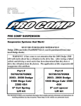
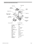
2360 Boswell Road Chula Vista, CA 91914 Phone 619.216.1444 Fax 619.216.1474 E-Mail [email protected] PRO COMP SUSPENSION Suspension Systems that Work! Part #51084/51084MX 1999-2005 Chevrolet Silverado 2WD W/ ONE PIECE REAR DRIVE SHAFT & 2005 & 2006 C1500 w/COIL SPRING FRONT END 7 Inch Lift Kit IMPORTANT: This kit will not fit 2005 & 2006 C1500 with torsion bar front end. This document contains very important information that includes warranty information and instructions for resolving problems you may encounter. Please keep it in the vehicle as a permanent record. 51084/ 51084MX REVISED 12.21.05 Part # Description Qty. Illus. Page 1 1 2 2 4 4 5 5 8 8 10 10 Box 1 of 5-PN 51084-1 / 51084MX-1 90-3306 90-3309 90-1705 90-1104 FRONT CROSS MEMBER REAR CROSS MEMBER COMPRESSION STRUT MOUNTS COMPRESSION STRUT MOUNTS Box 2 of 5-PN 51084-2 / 51084MX-2 90-4118 90-4119 90-6411 97-1078 FRONT KNUCKLE (DRIVERS) FRONT KNUCKLE (PASSENGER) HARDWARE PACK: STEERING STOPS STEERING STOP PLATES 1 1 1 2 11 6A,6B Box 3 of 5-PN 51084-3 / 51084MX-3 90-6227 70-0625001800 70-0625501800 72-062100816 73-06200034 HARDWARE PACK: CROSSMEMBERS 5/8” X 5 GR 8 HEXBOLT 5/8” X 5 1/2” GR 8 HEXBOLT 5/8” USS GR 8 STOVER NUT 5/8” SAE GR 8 WASHER 1 2 2 4 8 4 4 4 4 8 8 8 8 90-6262 70-0621501500 70-062100512 73-06200034 72-056100512 73-05000034 HARDWARE PACK: CROSSMEMBER BRACES 5/8” X1 1/2” GR 5 HEXBOLT 5/8” USS GR 5 NYLOCK NUT 5/8” SAE GR 8 WASHER 9/16” USS GR 5 NYLOCK NUT 9/16” SAE GR 8 WASHER 1 2 2 4 2 2 3 3 3 3 3 8 8 8 8 8 90-6234 70-0501251800 70-0504001800 72-050100816 73-05000032 90-2126 90-1582 HARDWARE PACK: COMPRESSION STRUTS 1/2” X 1 1/4” GR 8 HEX BOLT 1/2” X 4” GR 8 HEX BOLT 1/2” GR 8 STOVER NUT 1/2” USS GRADE 8 FLAT WASHER COMPRESSION STRUTS NUT PLATE -1/2” 1 2 4 4 10 2 2 5 5 5 5 5 5 10 10 10 10 10 10 90-6263 15-11148 90-2109 HARDWARE PACK: COMPRESSION STRUTS 1 COMPRESSION STRUT BUSHING 8 SLEEVE, COMPRESSION STRUT – 2.75” 4 5 5 10 10 90-6291 70-0252501800 72-025100816 73-02500838 70-0371501800 72-037100816 73-03700034 BRAKE LINE DROP KIT REAR 1/4” X 2 1/2” GR. 8 HEXBOLT 1/4” USS STOVER NUTS 1/4” PLATED WASHER 3/8” X 1 1/2” GR. 8 HEXBOLT 3/8” USS STOVER NUT 3/8” SAE GR. 8 FLAT WASHER B B B 12 12 12 2 1 2 2 4 2 2 4 51084/ 51084MX REVISED 12.21.05 Part # Description Qty. 90-2144 95-300 13-90087 BUMPSTOP EXTENSION 3” BLOCK 2 1/2” X 5” W/ 9/16” PIN 9/16” X 2.625 X 12.5” SQUARE U-BOLTS 2 2 4 90-6292 15-11031 72-037100512 73-03700530 90-2249 20-65302 13-10423 13-3033 90-2374 90-2376 90-1887 HARDWARE PACK: BUMPSTOP CONE BUMPSTOP 2 1/4” LONG 3/8” GR. 5 NYLOCK NUT 3/8” GR. 5 FLAT WASHER SPACER REAR BRAKE LINE DROP HARDWARE PACK: U-BOLT 9/16” NUTS SAE GR 8 9/16” HARDENED FLAT WASHERS CROSSMEMBER BRACES DRIVER CROSSMEMBER BRACES PASSENGER COIL SPACER 1 2 2 2 2 1 8 8 1 1 1 90-6325 15-11160 S10024 90-2419 90-6329 HARDWARE PACK: SWAY BAR KIT BUSHING WASHER SPACER HARDWARE PACK: SWAY BAR KIT 1 8 8 2 1 Illus. Page A A 10 10 4 4 4 B 8 8 8 12 A A 3 3 10 10 8 8 A 11 Box 4 of 5-PN 51084-4 / 51084MX-4 13127-1 1 1/2” ADD-A-LEAF 2 Box 5 of 5-PN 51084MX-5 MX 6028 MX 6098 MX6 FRONT SHOCKS MX6 REAR SHOCKS 2 2 OR Box 5 of 5-PN 51084-5 322515 327503 ES3000 FRONT SHOCKS ES3000 REAR SHOCKS Optional Equipment Available from your Pro 2 2 Comp Distributor! PRO COMP COIL SPRINGS PN 14514 ARE REQUIRED FOR THIS INSTALLATION. TRACTION BARS: 71311 SKID PLATE: 51103 DRIVE SHAFT ALIGNMENT KIT: 51255 Also, check out our outstanding selection of Pro Comp tires to compliment your new installation! 3 51084/ 51084MX REVISED 12.21.05 SPECIAL EQUIPTMENT Please refer to your service manual for more information. These tool may be purchased at your local GM dealer. 1. A special removal tool is required for safe removal of the tie rods. (Tie rod puller # J6627-A) 2. A special removal tool is required for safe removal of the ball joints. (Ball joint separator tool # J23742) 3. A special removal tool is required for safe removal of the coil springs. (Coil spring removal and installation tool # J23028-A). You may be able to rent any of these tools at your local parts store. Please Note: • • • • Front end and head light realignment is necessary! Speedometer and ABS recalibration will be necessary if larger tires (10% more than stock diameter) are installed. Due to differences in manufacturing, dimensions and inflated measurements, tire and wheel combinations should be test fit prior to installation. Tire and wheel choice is crucial in assuring proper fit, performance, and the safety of your Pro Comp equipped vehicle. For this application, we recommend a wheel not to exceed 8” in width with a minimum backspacing of 4” must be used. Additionally, a quality tire of radial design, not exceeding 35” tall X 12.5” wide is also recommended. Please note that the use of a 35” X 12.5” tire may require fender modification. Violation of these recommendations will not be endorsed as acceptable by Pro Comp Suspension and will void any and all warranties either written or implied. 2005 trucks require a 17” wheels to clear the calipers. CRITICAL INSTRUCTION PRO COMP COIL SPRINGS PN 14514 ARE REQUIRED FOR THIS INSTALLATION. Open the box with the new coil springs. Due to manufacturing variances the end of the coils may or may not have the same end wrap. When installing them the end wrap of the coil will effect how the coil sits in the a-arm. To check, place the coil on the floor and butt it against the wall, turn it around and do the same to the other side with the coil end in the same location. If one side sits flatter against the wall, mark it, this side should go to the top of the spring bucket. Failure to do this will cause excessive bow and difficulty with the installation of the shock. 4 51084/ 51084MX REVISED 12.21.05 Introduction: ♦ ♦ ♦ ♦ ♦ ♦ ♦ ♦ ♦ ♦ ♦ ♦ This installation requires a professional mechanic! We recommend that you have access to a GM service manual for your vehicle to assist in the disassembly and reassembly of your vehicle. It contains a wealth of detailed information. Prior to installation, carefully inspect the vehicle’s steering and driveline systems paying close attention to the tie rod ends, ball joints, wheel bearing preload, pitman and idler arm. Additionally, check steering-to-frame and suspension-to-frame attaching points for stress cracks. The overall vehicle must be in excellent working condition. Repair or replace all worn or damaged parts! Read the instructions carefully and study the illustrations before attempting installation! You may save yourself a lot of extra work. Check the parts and hardware against the parts list to assure that your kit is complete. Separating parts according to the areas where they will be used and placing the hardware with the brackets before you begin will save installation time. Check the special equipment list and ensure the availability of these tools. Secure and properly block vehicle prior to beginning installation. ALWAYS wear safety glasses when using power tools or working under the vehicle! Use caution when cutting is required under the vehicle. The factory undercoating is flammable. Take appropriate precautions. Have a fire extinguisher close at hand. Foot pound torque readings are listed on the Torque Specifications chart at the end of the instructions. These are to be used unless specifically directed otherwise. Apply thread lock retaining compound where specified. Please note that while every effort is made to ensure that the installation of your Pro Comp lift kit is a positive experience, variations in construction and assembly in the vehicle manufacturing process will virtually ensure that some parts may seem difficult to install. Additionally, the current trend in manufacturing of vehicles results in a frame that is highly flexible and may shift slightly on disassembly prior to installation. The use of pry bars and tapered punches for alignment is considered normal and usually does not indicate a faulty product. However, if you are uncertain about some aspect of the installation process, please feel free to call our tech support department at the number listed on the cover page. We do not recommend that you modify the Pro Comp parts in any way as this will void any warranty expressed or implied by the Pro Comp Suspension company. NOTE: 2004 Chevrolet standard cab with short bed and one piece rear drive shaft may require shorter rear shocks to limit the rear end droop. This will prevent the driveshaft from hitting the crossmember brace. MX6098 will solve this issue. 5 51084/ 51084MX REVISED 12.21.05 Front Installation Illustration 1 1. Prior to installing this kit, with the vehicle on the ground, measure the height of your vehicle. This measurement can be recorded from the center of the wheel, straight up to the top of the inner fender lip. Record the measurements below. LF: RF: LR: RR: 2. Ensure that your work space is of adequate size and the work surface is level. Place the vehicle in neutral. Place your floor jack under the front cross member and raise vehicle. Place jack stands under the frame rails behind the front wheel wells and lower the frame onto the stands. Remove the jack and place the vehicle back in gear, set the emergency brake, and place blocks both in front of and behind the rear wheels. Remove the wheels. 3. Remove any skid plates or debris shields from the bottom of the vehicle. NOTE: The factory compression struts can be left on the vehicle, if desired. Tie rod end puller/ Pitman arm puller Work on one side of the vehicle at a time. clear of the work area where it will not get damaged. 4. Remove the shock absorbers. Using a wrench hold the shock absorber stem while backing the nut off the stem. Remove the bottom bolts from the lower control arm and remove the shock from the bottom. 8. Remove the brake line clamp from the frame and control arm. 9. Remove the nuts from the tie rod ends. Using the tie rod end puller, remove the tie rod end from the OE knuckle. Save the nuts for reuse. Be careful that you do not damage the dust guard or the tie rod ends. SEE ILLUSTRATION 1. 5. Remove the sway bar end link assemblies from both sides of the vehicle. 6. Mark the sway bars orientation. Remove the mounts and the sway bar. 10. Remove the two bolts to the disk brake caliper, lift the calipers off the rotor. Use wire tie or tie wraps to secure them clear 7. If your vehicle is equipped with ABS brakes, disconnect the wiring. Move it 6 51084/ 51084MX REVISED 12.21.05 of the work area. 14. Install coil spring compressor tool and compress the coil spring. NOTE: Be careful that you do not damage the brake lines! Never hang the 15. locate the lower ball joint, remove the nut calipers from the brake lines! from the ball joint. Using the ball joint 11. Remove the disc brake rotor retaining separator tool apply pressure to the tool clips. Then remove the rotor and set it until the ball joint breaks loose from the clear of the work area. lower part of the front knuckle. 12. Using a floor jack support the front lower 16. Locate the upper ball joint, remove the nut control arm near the spring seat. Raise the from the ball joint. Using the ball joint jack until it just supports the lower control separator tool apply pressure to the tool arm. until the ball joint breaks loose from the upper part of the knuckle. CAUTION: The floor jack must remain under the front control arm spring 17. Slowly release the floor jack until all of the seat during disassembly to retain the pressure has been released. Remove the spring and control arm position or perfront coil spring and the compressor. sonal injury may result. 18. Remove the knuckle. 13. Mark the end of the springs location in the 19. Remove the three bolts from the backside bucket for new coil installation. attaching the bearing/ stud assembly and the dust shield from the OE knuckle. Set these parts aside for installation on new OE Bolt knuckle. Illustration 2 20. Install the three OE bolts to the backside of the new knuckle attaching the bearing/ stud assembly and the dust shield. Make sure drivers hardware goes to the new drivers knuckle and the passengers goes to the passengers knuckle. Torque this hardware to factory specs. 21. Remove the nuts, washers and bolts fastening the lower control arm to the frame. Set these parts aside for future use. OE Bolt 22. Remove the lower control arms. Rear crossmember 90-3309 23. Remove the factory bump stops. 24. Repeat on other side of the vehicle. 25. Install the front cross-member, 90-3306, into the existing front lower control arm mounting position, using the OEM hard ware previously removed. Make sure that the bolt heads are facing towards the front of the vehicle. Do not fasten at this time. Front crossmember 90-3306 26. Place the rear cross-member, 90-3309, 7 51084/ 51084MX REVISED 12.21.05 90-2376 PASS Illustration 3 5/8” X1 1/2” 90-2374 DRIVERS 90-3306 90-3309 into the existing lower control arm mount11031 to the new rear cross-member. ing position using the OEM hardware pre- 29. Install the lower control arms into the new viously removed. Make sure that the bolt front and rear cross-member mounting arheads are facing to the rear of the vehicle. eas. Place strut mount bracket (PN 90Do not fasten at this time. SEE ILLUS1705) on the bolt then install the bolt to the TRATION 2. rear of the lower NOTE: Some Illustration 4 trucks have factory 5/8” x 5” 15-11031 drivers mounting tabs located underneath the rear cross member. These will need to be removed if the cross member will not fit properly. 5/8” x 5 1/2” 27. Install cross member braces (90-2374 DRIVERS and 902376 PASS.) with the supplied hardware from pack 90-6262. 28. With the supplied 3/8” hardware from pack 90-6292, attach the bump stops 15- 90-3306 90-3309 8 Strut mount 90-1705 51084/ 51084MX REVISED 12.21.05 lbs. control arm. Use 5/8” X 5.5” hardware provided from pack 90-6227. Make sure that the rear bolts heads are facing to the rear of the vehicle. Make sure that the front bolts heads are facing to the front of the vehicle. Do not torque at this time. SEE ILLUSTRATION 2. 40. Torque the upper ball joint nut to 74 ft./ lbs. 41. Repeat on other side of the vehicle. 42. If applicable, re-attach ABS sensors to the factory harness. NOTE: Make sure the ABS wire runs on the a-arm so the tire will not hit it. 30. Repeat on other side of the vehicle. 31. Torque existing upper sub-frame nuts and bolts to 100 ft./lbs. Starting with the front then the rear. 43. Install brake rotor onto the front spindle. 32. Using a floor jack support the front lower control arm near the spring seat. Install the coil spring insulators previously removed from the old spring in the same location on to the new coil PN 14514. NOTE: See critical instructions. 44. Attach the brake caliper assembly to the new front spindle. Torque the bolts to 125-169 ft./lbs. SEE ILLUSTRATION 3. 33. Refer to the measurements taken at step 1. If you trucks height is off more than 3/8”-1/2” install the coil spacer 90-1887 on top of the coil, at the time of install, to the side that is shorter. 46. Reinstall the tie rod ends and fasten with the OEM nuts. 34. Position the coil spring on the lower control arm spring seat. Match up with the mark from the original coils location. 48. Repeat on other side of the vehicle. 45. Install the new Pro Comp shock absorber PN 322515 or MX 6028 through the front coil. 47. Install and torque the tie rod ends to 40 ft./lbs. 49. Flip the sway bar over and install the sway bar and mounts back on the vehicle. 35. While the lower control arm is supported with the floor jack, compress the coil with the spring compressor. Place the top of the spring in the upper frame spring pocket. 50. Install sway bar to the lower control arm using the sway bar hardware from pack 90-6325. 51. Loosen the factory brake line in the factory bracket by prying it open. Attach the existing brake line hose clamp to knuckle. Make sure that the brake line does not interfere with any of the moving suspension components. 36. Install new front knuckle (90-4078 DRIVERS and 90-4079 PASSENGER) to lower control arm ball joint. Fasten with the OEM nuts. NOTE: Make sure the brake line is behind the knuckle. 52. Make sure you can cycle the suspension from lock to lock. 37. Raise the lower control arm using the floor jack. Attach the front knuckle to the upper ball joint. Fasten with the OEM nuts. 38. Remove the coil spring compressor tool. 53. Cycle the suspension through full travel cycle and check for adequate clearance between sway bar end links, shocks, bump stops and brake line hoses. 39. Torque the lower ball joint nut to 94 ft./ 54. Raise the lower controls arm to the new 9 51084/ 51084MX REVISED 12.21.05 ride height. This is the measurement from step one plus 5.5– 6.0 inches. Torque the 5/8” hardware (lower control arms) to 100 ft./lbs. ward until the bracket contacts the bottom of the transmission cross member. Using the bracket as a guide, mark and center punch the mounting hole locations. NOTE: Struts may angle in towards the center of the of the cross member, or out towards the frame. Choose the best place to mount depending on your engine and transmission combination. 55. Install the bushings and sleeves into both ends of the compression struts PN 902126. 56. With the angled end towards the front of the truck, attach the compression struts to the strut mount brackets located on the rear cross member, using the supplied 1/2” hardware provided in pack 90-6234. Do not tighten at this time. SEE ILLUSTRATION 5. 58. Drill a 1/2” diameter hole at each of the marked locations. 59. Install the bracket 90-1104 with the nut plate 90-1582 and the 1/2” X 1 1/4” hardware provided. Reinstall the compression struts using the supplied 1/2” X 57. Attach the strut mount PN 90-1104 to the other end of the compression strut. Rotate the compression strut assembly up- Illustration 5 90-1582 Passenger side Typical location 90-1104 1/2” X 1 1/4” 90-1705 COMPRESSION STRUT HARDWARE 1/2” X 4” COMPRESSION STRUT 90-2126 10 51084/ 51084MX REVISED 12.21.05 4” hardware. Illustration 6A 60. Repeat on the other side. Steering Stop 61. Torque the 1/2” hardware to 65 ft./lbs. FACTORY STEERING STOP 62. Install your wheels and tires and lower the vehicle to the ground. Tighten the lug nuts to 90 ft./lbs. 63. Torque sway bar ends to 13 ft./lbs. NOTE: Recommended for 2006: At ride height if the steering knuckle contacts the sway bar end links you can weld the included (97-1078) to the front steering stops on the lower control arms. SEE ILLUSTRATION 6A & 6B. Also, reinstall the OE sway bar end links in place of the supplied end link kit (90-6325). FRONT LOWER A-ARM STEERNG STOP 97-1078 64. On both sides of the vehicle at ride height and full droop, check the routing of the brake lines and the ABS wire harnesses. There must be no pinching, rubbing, or stretching of either component. Use zip ties to secure these items to the steering components. Cycle the steering from lock to lock while observing the reaction of these components. Reposition them if needed. Illustration 6B Steering Stop FINISHED VIEW 65. Recheck for proper installation and torque all newly installed hardware. WELD 66. After 100 miles recheck for proper torque on all newly installed hardware. 67. Have your headlights adjusted. 68. Recheck all hardware for tightness after off road use. ATTENTION: If there is drive line vibration after you install the lift kit. Install the 90-6326 HARDWARE PACK: Drive shaft shim kit and supplied hardware to drop the drive shaft carrier bearing. Any combination of these shims can be used to eliminate the vibration. 11 51084/ 51084MX REVISED 12.21.05 12 51084/ 51084MX REVISED 12.21.05 Rear Installation: raise the axle to unload the shocks for removal. 5. Support the rear axle with a floor jack and loosen the U-bolts on the passenger side. remove the U-bolts on the driver side. 6. Install the add a leaf following the enclosed instructions. 7. If you have Pro Comp Traction bars install the axle mount at this time. 1. Block the front tires and raise the rear of the vehicle. Support the frame with jack stands forward of the rear springs. 2. Remove the wheels and tires. 3.Remove the retaining clips on the wheel studs. 4. Remove the shocks on both sides of the vehicle. It may be necessary that you slightly DO NOT allow the axle to hang by any hoses or cables. ADD-A-LEAF 13127-1 Illustration A 13-90087 DRIVERS SIDE Arrow to front Axle to front 95-300 13 51084/ 51084MX REVISED 12.21.05 hands. 8. Remove the factory pinion wedge plates placed on the factory blocks or springs. 14.Install existing bump stop to the provided bump stop drop. Install bump stop drop 902144 to the truck with the supplied 3/8” hardware. NOTE: On some 4 door models the factory pinion wedge may need to be rotated 180 degrees in order for the driveshaft yoke to properly fit into the transmission. 15. Install your new Pro Comp shocks PN 327503 or MX 6098, shaft up, and torque this hardware to 60 ft. lbs. 9. Install the lift block on the axle pad and use your floor jack to raise the axle to the spring. Apply a slight amount of pressure with your floor jack against the spring pack and engage the centering stud into the locating hole at the top of the lift block. Secure the assembly with the U-bolts supplied in hardware pack and new high-nuts and washers from hardware pack. Do not tighten the U-bolts at this time. See Illustration A. NOTE: make sure the block sits flush on the axle perch. 16. Reinstall the wheels and tires and lower the vehicle to the ground. 17. Recheck the wheel lug torque on all four wheels at this time. 18. Recheck all hardware for proper installation and torque at this time. 19. On completion of the installation, have the suspension and headlights re-aligned. NOTE: You may trim the plastic fender trim as needed. 10. Repeat the installation on the other side of the vehicle. 11. When the installation of the remaining side is complete, torque the Ubolts to 115 ft. lbs. 12.On the drivers side, remove the existing brake line bracket. 13. Install the brake line drop spacers using the enclosed 1/4” hardware from hardware pack 90-6291 and the spacers 90-2249. See illustration B. NOTE: Make sure the hard lines do not rub against the frame. If they do you can carefully bend them out of the way with your 90-2249 1/4” X 2 1/4” Illustration B Rear Drivers 14 51084/ 51084MX REVISED 12.21.05 15 Notice to Owner operator, Dealer and Installer: Vehicles that have been enhanced for off-road performance often have unique handling characteristics due to the higher center of gravity and larger tires. This vehicle may handle, react and stop differently than many passenger cars or unmodified vehicles, both on and off–road. You must drive your vehicle safely! Extreme care should always be taken to prevent vehicle rollover or loss of control, which can result in serious injury or even death. Always avoid sudden sharp turns or abrupt maneuvers and allow more time and distance for braking! Pro Comp reminds you to fasten your seat belts at all times and reduce speed! We will gladly answer any questions concerning the design, function, maintenance and correct use of our products. Please make sure your Dealer/Installer explains and delivers all warning notices, warranty forms and instruction sheets included with Pro Comp product. Application listings in this catalog have been carefully fit checked for each model and year denoted. However, Pro Comp reserves the right to update as necessary, without notice, and will not be held responsible for misprints, changes or variations made by vehicle manufacturers. Please call when in question regarding new model year, vehicles not listed by specific body or chassis styles or vehicles not originally distributed in the USA. Please note that certain mechanical aspects of any suspension lift product may accelerate ordinary wear of original equipment components. Further, installation of certain Pro Comp products may void the vehicle’s factory warranty as it pertains to certain covered parts; it is the consumer’s responsibility to check with their local dealer for warranty coverage before installation of the lift. Warranty and Return policy: Pro Comp warranties its full line of products to be free from defects in workmanship and materials. Pro Comp’s obligation under this warranty is limited to repair or replacement, at Pro Comp’s option, of the defective product. Any and all costs of removal, installation, freight or incidental or consequential damages are expressly excluded from this warranty. Pro Comp is not responsible for damages and / or warranty of other vehicle parts related or non-related to the installation of Pro Comp product. A consumer who makes the decision to modify his vehicle with aftermarket components of any kind will assume all risk and responsibility for potential damages incurred as a result of their chosen modifications. Warranty coverage does not include consumer opinions regarding ride comfort, fitment and design. Warranty claims can be made directly with Pro Comp or at any factory authorized Pro Comp dealer. IMPORTANT! To validate the warranty on this purchase please be sure to mail in the warranty card. Claims not covered under warranty• Parts subject to normal wear, this includes bushings, bump stops, ball joints, tie rod ends and heim joints • Discontinued products at Pro Comp’s discretion • Bent or dented product • Finish after 90 days • Leaf or coil springs used without proper bump stops • Light bulbs • Products with evident damage caused by abrasion or contact with other items • Damage caused as a result of not following recommendations or requirements called out in the installation manuals • Products used in applications other than listed in Pro Comp’s catalog • Components or accessories used in conjunction with other manufacturer’s systems • Tire & Wheel Warranty as per Pro Competition Tire Company policy • Warranty claims without “Proof of Purchase” • Pro Comp Pro Runner coil over shocks are considered a serviceable shock with a one-year warranty against leakage only. Rebuild service and replacement parts will be available and sold separately by Pro Comp. Contact Pro Comp for specific service charges. • Pro Comp accepts no responsibility for any altered product, improper installation, lack of or improper maintenance, or improper use of our products. E-Mail: [email protected] Website: www.explorerprocomp.com Fax: (619) 216-1474 Ph: (619) 216-1444 PLACE WARRANTY REGISTRATION NUMBER HERE: __________________