1
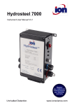
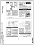
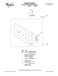
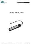
A-20-HHT:TEMPLATE
9/27/10
10:55 AM
Page 1
Bulletin A-20-HHT
Series HHT Hazardous Area Humidity/Temperature Transmitter
Specifications - Installation and Operating Instructions
4-9/32
[108.74]
4-15/32
[113.51]
2-23/32
[69.06]
1/2 NPT
13-23/32
[347.98]
1/2 NPT
3-29/32
[99.22]
1/2 NPT
The Series HHT Hazardous Area Humidity/Temperature
Transmitter takes accurate measurements in the harshest of
environments. The transmitter is offered in explosion-proof and
intrinsically-safe versions depending on the applications
requirements. The explosion-proof model is offered with 4 to 20
mA outputs for humidity only. The intrinsically-safe version is
offered with 4 to 20 mA output for humidity and temperature.
Both versions have an optional two line alphanumeric display to
show the current humidity and temperature.
The Series HHT humidity/temperature transmitter is excellent for
offshore HVAC applications, dust and grain applications.
DWYER INSTRUMENTS, INC.
P.O. BOX 373 • MICHIGAN CITY, INDIANA 46361, U.S.A.
SPECIFICATIONS
Relative Humidity Range: 0 to 100% RH.
Temperature Range: -40 to 140°F (-40 to 60°C).
Accuracy: ±2% 10-90% RH, ±0.9°F at 72°F (±0.3°C at 25°C).
Hysteresis: ±1%.
Repeatability: ±0.1% typical.
Temperature Limits: -40 to 140°F (-40 to 60°C).
Storage Temperature: -40 to 176°F (-40 to 80°C).
Compensated Temperature: -40 to 140°F (-40 to 60°C).
Power Requirements: For intrinsically safe models HHT-IX, 9.5
to 28 VDC. For explosion-proof models HHT-EX, 16.5 to 28
VDC.
Output Signal: 4-20 mA, 2 channels for humidity/temperature
models (loop power on RH).
Response Time: 15 seconds.
Electrical Connections: Screw terminal block.
Conduit Connection: 1/2 female NPT.
Drift: <1% RH/year.
RH Sensor: Capacitance polymer.
Temperature Sensor: Solid state band gap.
Housing Material: Aluminum.
Display: Optional 2 line alpha numeric, 8 characters/line.
Temperature
display is ˚F/˚C selectable.
Display Resolution: RH: 0.1%: Temperature 0.1°F (0.1°C).
Weight: 2 lb 8 oz (1134 g).
Enclosure Rating: NEMA 4x (IP66). Models HHT-EX: FM
Explosion Proof, Class I Div. 1 Group B, C, D, Class II Div. 1
Group E, F, G, Class III Div. 1; Models HHT-IX: FM Intrinsically
Safe, Class I Div. 1 Group A, B, C, D, Class II Div. 1 Group E, F,
G, Class III Div. 1 T4.
Agency Approvals: FM, CE.
Phone: 219/879-8000
Fax: 219/872-9057
www.dwyer-inst.com
e-mail: [email protected]
A-20-HHT:TEMPLATE
9/27/10
10:55 AM
Page 2
Wiring Diagram – Humidity Only
Explosion Proof Installation Notes:
1. Install in accordance with any applicable national electric
code.
2. Plug unused conduit openings. Plug must engage a minimum
of 5 threads.
3. Use conduit seal within 18 inches of conduit entry.
4. Disconnect power before servicing.
5. Control equipment voltage on hazardous side is 250 Vrms/DC
maximum.
6. Do not substitute any components. The intrinsic safety of the
sensor may be compromised.
7. Shielded cable for 4-20 mA loop is necessary to meet CE
requirements or when used in electrically noisy environments.
Wiring Diagram – Humidity and Temperature
Intrinsically Safe Installation Notes:
1. Remove power from the instrument before carrying out any
servicing.
2. Return the instrument to the manufacturer for any repair. Any
unauthorized repairs may impair the intrinsic safety of the
instrument.
3. Use only FM approved Associated Apparatus. When installing
the Associated Apparatus, the manufacturer’s instructions
must be followed.
4. Install in accordance with ANSI/ISA RP12.06.01, and the
National Electric Code ANSI/NFPA 70.
5. The earth terminal on the housing must be wired to a local
earth ground in the hazardous area.
6. Refer to FM control drawing, Dwyer number 03-001467-00.
7. For Model HHT-IT, use ONLY Pepperl + Fuchs KFDØ-SCSEx1.55 Galvanically Isolated Barriers.
HAZARDOUS SIDE
HAZARDOUS SIDE
NON-HAZARDOUS SIDE
SHOWN TRANSPARENT
FOR CLARITY
250 OHMS
CONVERSION RESISTOR
4-20 mA
LOOP
SUPPLY
NON-HAZARDOUS SIDE
MODEL HHT-IT, RH AND TEMP.
INTRINSICALLY SAFE WIRING
EXAMPLE USING PEPPERL + FUCHS
BARRIER SYSTEM
SHOWN TRANSPARENT
FOR CLARITY
NOTE! THE PEPPERL +
FUCH KFD0-SCS-Ex1.55 4-20 mA
LOOP SUPPLY
BARRIERS ARE
GALVANICALLY ISOLATED,
SO GROUNDING IS NOT
REQUIRED.
IF SHIELDED CABLE IS USED FOR
4-20 mA LOOP, GROUND THIS SIDE
OF CABLE ONLY
MODEL HHT-IT
FIGURE 1
KFD0-SCS-Ex1.55
RH
RECEIVER
KFD0-SCS-Ex1.55
TEMP.
RECEIVER
I.S GROUND
IF SHIELDED CABLE IS USED
GROUND THIS SIDE OF CABLE ONLY
FIGURE 2
MODEL HHT-IU, RH ONLY
INTRINSICALLY SAFE WIRING
EXAMPLE USING MTL BARRIER
SYSTEM
Entity Parameters:
Vmax = 28 VDC
Imax = 100 mA
Ci = 62 nF
Li = 7.7 µH
Pi = 651 mW
HAZARDOUS SIDE
NON-HAZARDOUS SIDE
4-20 mA
LOOP SUPPLY
SHOWN TRANSPARENT
FOR CLARITY
MTL7787+
RH
RECEIVER
I.S GROUND
IF SHIELDED CABLE IS USED,
GROUND THIS SIDE OF CABLE ONLY
MODEL HHT-IU
FIGURE 3
A-20-HHT:TEMPLATE
9/27/10
10:55 AM
Page 3
Power Supply Requirements:
The maximum DC Power Supply is 28 VDC. The minimum
required DC Power Supply required is based upon the following:
1.Minimum DC voltage requirement of the Model HHT.
2.Total load resistance.
3.Total leadwire resistance.
4.Zener barrier voltage drop ( Model HHT-IX only).
The formula for calculating the DC Power Supply is:
VDC = VHHT + VLOAD + VLEADWIRE + VBARRIER
Where VHHT = 9.5v for Models HHT-IX and 16.5v for Models
HHT-EX.
VLOAD = Total load resistance X 20mA
VLEADWIRE = Total leadwire resistance X 20mA
VBARRIER = 8.1v
(Typical zener barrier voltage drop for this application)
Example 1. Calculate minimum DC Power Supply for
Model HHT-EX (Explosion Proof)
Step 1. VHHT = Minimum voltage required by
Model HHT-EX = 16.5 v
Step 2. Calculate VLOAD. Using the industry standard
250 OHM conversion resistor, VLOAD =
250 X 20mA = 5v.
Step 3. Calculate VLEADWIRE. For this example assume
a leadwire resistance of 10 OHMS.
VLEADWIRE = 10 X 20mA = 0.2v
Step 4. VDC = VHHT + VLOAD + VLEADWIRE =
16.5 + 5 + 0.2 = 21.2v
Example 2. Calculate minimum DC Power Supply for
Model HHT-IU (Intrinsically Safe)
Step 1. VHHT = Minimum voltage required by Model HHTIX = 9.5 v
Step 2. Calculate VLOAD. Using the industry standard
250 OHM conversion resistor, VLOAD =
250 X 20mA = 5v.
Step 3. Calculate VLEADWIRE. For this example assume
a leadwire resistance of 10 OHMS.
VLEADWIRE = 10 X 20mA = 0.2v
Step 4. VBARRIER = 8.1v
Step 5. VDC = VHHT + VLOAD + VLEADWIRE +
VBARRIER = 9.5 + 5 + 0.2 +8.1 = 22.8v
For Model HHT-IT, follow instructions with Pepperl + Fuchs
KFDØ-SCS-Ex1.55 Barrier.
INSTALLATION
Location: Select a location where the ambient temperature is
between –40 to +140°F (-40 to +60°C)
Position: The transmitter is not position sensitive. Units with the
optional display should be mounted for ease of viewing the
display.
Caution: Use electrostatic discharge precautions (e.g. use of
wrist straps) during installation and wiring to prevent equipment
damage.
Avoid locations where severe shock or vibration, excessive
moisture or corrosive fumes are present.
Do not exceed ratings of this device. Permanent damage not
covered by the warranty may result.
Display: The temperature indicated on the display, if equipped
with the LCD option, is field selectable via a jumper located on
the circuit board just above the display. To change the jumper
position, remove the housing cover and position the jumper for
°F or °C according to Figure 4.
FIGURE 4
Replaceable RH/Temperature sensor and sintered filter:
Replacement sensors are available. No calibration is required
when a new sensor is installed. To replace the sensor, remove
the sintered filter. When installing the new sensor, make sure the
4 pin male connector is aligned correctly with the female
connector. See Figure 5.
To order a replacement sensor or sintered filter, contact Dwyer
sales. The part numbers are:
Replacement 2% sensor : A-451
Replacement sintered filter: A-450
CORRECT ALIGNMENT
OF SENSOR ASSEMBLY
INCORRECT ALIGNMENT
OF SENSOR ASSEMBLY
FIGURE 5
MAINTENANCE
Upon final installation of the Series HHT Hazardous Area
Humidity / Temperature Transmitter, no routine maintenance is
required. A periodic check of system calibration is
recommended. The Series HHT is not field serviceable and
should be returned if repair is needed (field repair should not be
attempted and may void warranty). Be sure to include a brief
description of the problem plus any relevant application notes.
Contact customer service to receive a return goods
authorization number before shipping.
©Copyright 2010 Dwyer Instruments, Inc.
DWYER INSTRUMENTS, INC.
P.O. BOX 373 • MICHIGAN CITY, INDIANA 46361, U.S.A.
OPTIONAL SHIELD
4
3
2
I.S. SAFETY GROUND
G
GROUND CONNECTION
2
1
NON-HAZARDOUS LOCATION
G
GROUND CONNECTION
Printed in U.S.A. 9/10
Phone: 219/879-8000
Fax: 219/872-9057
NO.
CHANGES
BY/DATE
LRR
APPD
CAT
CHKD
KAS
DWN BY
8-25-08
DATE
NAME
SCALE 1:2
03-001467-00
MICHIGAN CITY, INDIANA 46360 U.S.A.
FINISH
MATERIAL
CD = CRITICAL DIMENSION
STANDARD TOLERANCES UNLESS NOTED:
ALL DECIMAL DIMENSIONS ± .005
ALL ANGLES ± 1°
ACAD2002 FR. NO.
3
FM CONTROL DRAWING
HHT-IU AND HHT-IT
FM CONTROL DRAWING
1. THE INTRINSIC SAFETY ENTITY CONCEPT ALLOWS THE INTERCONNECTION OF TWO FM APPROVED INTRINSICALLY SAFE
DEVICES WITH ENTITY PARAMETERS NOT SPECIFICALLY EXAMINED IN COMBINATION AS A SYSTEM WHEN:
Voc OR Uo OR Vt ≤ Vmax, Isc OR lo OR It ≤ Imax, Co or Co ≥ Ci + Ccable, Lo OR Lo ≥ Li + Lcable, Po ≤ Pi
2. EQUIPMENT CONNECTED TO THE ASSOCIATED APPARATUS MUST NOT USE OR GENERATE MORE THAT 250 Vrms OR VDC
3. INSTALLATION MUST IN ACCORDANCE WITH THE NATIONAL ELECTRICAL CODE (NFPA 70, ARTICLE 504) AND ANSI/ISA-RP12.6
4. NO REVISIONS WITHOUT PRIOR APPROVAL FROM FM RESEARCH.
5. THE ASSOCIATED APPARATUS MANUFACTURES INSTALLATION INSTRUCTIONS MUST BE FOLLOWED WHEN INSTALLING THIS EQUIPMENT.
6. DUST TIGHT CONDUIT SEAL MUST BE USED IN CLASS II AND CLASS III ENVIRONMENTS.
HAZARDOUS (CLASSIFIED) LOCATION
INTRINSICALLY SAFE FOR:
CLASS I DIV. 1 GROUPS A, B, C, D
CLASS II DIV. 1 GROUPS E, F, G
CLASS III DIV. 1
T4 TEMPERATURE CODE BASED ON
60°C AMBIENT
TEMPERATURE –
4
RH –
Vmax=28VDC
Imax=100mA
Ci=62nF
Li=7.7µH
Pi=651mW
1
10:55 AM
PROBE TUBE
UP TO LINE
IS NOT
NEMA 4X
IP66
HOUSING ABOVE
THIS LINE IS
NEMA 4X IP66
3
COM +
FM APPROVED
ASSOCIATED APPARATUS
9/27/10
HHT SERIES
TRANSMITTER
CATALOG NUMBERS
HHT-IU AND HHT-IT
03-001467-00
A-20-HHT:TEMPLATE
Page 4
FR# 03-443603-00 Rev.4
www.dwyer-inst.com
e-mail: [email protected]
03-001467-00