1
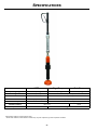
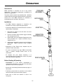
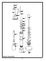
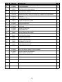
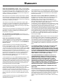
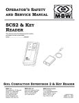
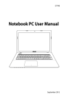
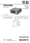
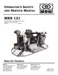
OPERATOR’S SAFETY
AND SERVICE MANUAL
VIBRATION
SUPPRESSOR
& ERGOTAMP
This manual covers the following serial numbers
and higher for each model listed:
VS77...........1110640
VS77M........1110640
ErgoTamp....2110258
PROBLEM SOLVING TECHNOLOGIES
MBW, Inc.
MBW (UK) Ltd.
MBW FRANCE S.A.R.L.
250 Hartford Rd • PO Box 440
Slinger, WI 53086-0440
Phone: (262) 644-5234
Fax: (262) 644-5169
Email: [email protected]
Website: www.mbw.com
Units 2&3 CochraneStreet
Bolton BL3 6BN
England, UK
Phone: 44 (0) 01204 387784
Fax: 44 (0) 01204 387797
E-mail: [email protected]
Z.A. d’Outreville
5 Rue Jean Baptiste Néron,
60540 BORNEL
France
Phone:+33 (0) 3 44 07 15 96
Fax: +33 (0) 3 44 07 41 28
Email: [email protected]
L18678 / 2.14L
©MBW, Inc. 2014
Printed in the USA
TABLE OF CONTENTS
Safety Information . . . . . . . . . . . . . . . . . . . . . . 1
Tamper Oil . . . . . . . . . . . . . . . . . . . . . . . . . . . . . . . . . 5
Introduction . . . . . . . . . . . . . . . . . . . . . . . . . . . . . . . . . 1
Vibration Suppressor Oil . . . . . . . . . . . . . . . . . . . . . . 5
Safety Precautions . . . . . . . . . . . . . . . . . . . . . . . . . . . 1
Service. . . . . . . . . . . . . . . . . . . . . . . . . . . . . . . . 6
Safety Decals . . . . . . . . . . . . . . . . . . . . . . . . . . . . . . . 1
Specifications. . . . . . . . . . . . . . . . . . . . . . . . . . 2
Operation . . . . . . . . . . . . . . . . . . . . . . . . . . . . . 3
General. . . . . . . . . . . . . . . . . . . . . . . . . . . . . . . . . . . . 6
Vibration Suppressor Disassembly . . . . . . . . . . . . . . 6
Vibration Suppressor Assembly . . . . . . . . . . . . . . . . . 6
Tamper Disassembly. . . . . . . . . . . . . . . . . . . . . . . . . 6
Introduction . . . . . . . . . . . . . . . . . . . . . . . . . . . . . . . . . 3
Tamper Assembly . . . . . . . . . . . . . . . . . . . . . . . . . . . 7
Installation. . . . . . . . . . . . . . . . . . . . . . . . . . . . . . . . . . 3
Suppressor Replacement Cycles and Tolerances . . . 7
Before Starting & Operating . . . . . . . . . . . . . . . . . . . . 3
Tamper Replacement Cycles and Tolerances . . . . . . 7
Operating Ergo and Pole tamps . . . . . . . . . . . . . . . . . 4
Storage . . . . . . . . . . . . . . . . . . . . . . . . . . . . . . . . . . . . 4
Maintenance . . . . . . . . . . . . . . . . . . . . . . . . . . . 5
Maintenance Schedule . . . . . . . . . . . . . . . . . . . . . . . . 5
Fluid Levels. . . . . . . . . . . . . . . . . . . . . . . . . . . . . . . . . 5
Replacement Parts . . . . . . . . . . . . . . . . . . . . . . 9
Vibration Suppressor Assembly . . . . . . . . . . . . . . . . 10
Threaded Adapters. . . . . . . . . . . . . . . . . . . . . . . . . . 12
Tamper Assembly . . . . . . . . . . . . . . . . . . . . . . . . . . 14
Warranty . . . . . . . . . . . . . . . . . . . . . . . . . . . . . 16
This page intentionally left blank
SAFETY INFORMATION
Introduction
NOISE PROTECTION: Wear OSHA specified
hearing protection devices.
This Safety Alert Symbol is used to call attention
to items or operations which may be dangerous
to those operating or working with this
equipment.
The symbol can be found
throughout this manual and on the unit. Please read these
warnings and cautions, along with all decals, carefully
before attempting to operate the unit. Make sure every
individual who operates or works with this equipment is
familiar with all safety precautions.
EYE PROTECTION: Wear OSHA specified
eye shields, safety glasses, and sweat bands.
FOOT PROTECTION: Wear OSHA specified
steel-tipped safety shoes.
HEAD PROTECTION: Wear OSHA specified
safety helmets.
WARNING
GENERAL WARNING.
Indicates information
important to the proper operation of the
equipment. Failure to observe may result in
damage to the equipment and/or severe bodily
injury or death.
DUST PROTECTION: Wear OSHA specified
dust mask or respirator.
OPERATOR: Keep children and bystanders
off and away from the equipment.
CAUTION
GENERAL CAUTION.
Indicates information
important to the proper operation of the
equipment. Failure to observe may result in
damage to the equipment.
REFERENCES: For details on safety rules and regulations
in the United States, contact your local Occupational Safety
and Health Administration (OSHA) office. Equipment
operated in other countries must be operated and serviced
in accordance and compliance with any and all safety
requirements of that country. The publication of these
safety precautions is done for your information. MBW does
not by the publication of these precautions, imply or in any
way represent that these are the sum of all dangers present
near MBW equipment.
If you are operating MBW
equipment, it is your responsibility to insure that such
operation is in full accordance with all applicable safety
requirements and codes. All requirements of the United
States Federal Occupational Safety and Health
Administration Act must be met when operated in areas that
are under the jurisdiction of that United States Department.
Safety Precautions
LETHAL EXHAUST GAS: An internal
combustion engine discharges carbon
monoxide, a poisonous, odorless, invisible
gas. Death or serious illness may result if
inhaled. Operate only in an area with proper
ventilation.
NEVER OPERATE IN A
CONFINED AREA!
SAFETY GUARDS: It is the owner's
responsibility to ensure that all guards and
shields are in place and in working order.
Safety Decals
SAFE DRESS: Do not wear loose clothing,
rings, wristwatches, etc. near machinery.
The MBW Vibration Suppressor has a warning scribed into
the body tube of the device. If this warning becomes
damaged or unreadable, replace outer tube. This
component is available from authorized MBW distributors.
-1-
SPECIFICATIONS
VS77
Ergo-Tamp
Pole-Tamp
Operating Weight
6.8 lb (3.1 kg)
48 lb (22 kg)
38 lb (17 kg)
Length
17 in (43 cm)
56 in (142 cm)
Foot Diameter
--
6.0 in (15 cm)
Maximum Pressure
140 psi (965 KPa)
90 psi (620 KPa)
Air Consumption
--
38.5 cfm (1.1 m3/m)
Vibration Isolation
Blows per Minute
up to 77%*
--
None
800 @ 90 PSI
Specifications subject to change without notice
* Under ideal conditions, actual vibration isolation may vary with compactor type and compaction conditions
-2-
OPERATION
Introduction
75,**(5
$66(0%/<
MBW equipment is intended for use in very severe
applications. The Vibration Suppressor is available in a
variety of configurations.
This parts manual contains only standard parts. Variations
of these parts as well as other special parts are not included.
Contact your local MBW distributor for assistance in
identifying parts not included in this manual.
(;7(16,21
3,3(
Installation
• The MBW Vibration suppressor is intended to be
installed on a variety of pneumatic pole tampers.
$'$37(5
• Connection adapters are included with some models to
add flexibility to installation
1.
Disconnect air supply to tool and make sure all air
pressure is released
2.
Unscrew connector pipe between trigger assembly
and main percussion unit
3.
Attach “ROD” end of the Vibration Suppressor to the
main percussion unit. Tighten connection using a
supplied lock-nut
4.
Attach trigger assembly to other end of the Vibration
Suppressor. Tighten connection using a supplied
lock-nut
9,%5$7,21
68335(6625
• Depending on Pole Tamper style, adapters may be
needed to make connections
• To ensure connections stay tight, MBW recommends
using a medium strength thread locker on all
connections
• To lengthen the pole tamper assembly, it is
recommended that the added pipe section be placed
above the Vibration Suppressor
3(5&866,21
81,7
Before Starting & Operating
• REMEMBER! It is the owner’s responsibility to
communicate information on the safe use and proper
operation of this unit to the operators.
• Review ALL of the Safety Precautions listed on page 1 of
this manual.
• Familiarize yourself with the operation of the machine
and confirm that all controls function properly.
• Know how to STOP the machine in case of an
emergency.
-3-
• Make sure hands, feet, and clothing are at a safe
distance from any moving parts.
• The MBW Vibration Suppressor should only be run with
clean and dry compressed air. The use of an oil mist
lubrication system will improve the life of both the
Vibration Suppressor and the pole tamper
Follow all recommended operating procedures of
pole tamper manufacturer. Failure to do so could
result in serious bodily injury or death.
Grasp pole tamper assembly on the main body of the
Vibration Suppressor or anywhere above
Release trigger to stop device.
• The MBW Vibration Suppressor is a spring loaded
device. Efficiency of isolation will depend on many
factors including air pressure, pole tamper type and
operator input. When operating, try to find the correct
down pressure that results in the least amount of
transmitted vibration.
WARNING
2.
4.
PINCH HAZARD: Avoid placing hands below main
body of the MBW Vibration Suppressor
Operating Ergo and Pole tamps
Connect air supply hose to trigger assembly
Depress trigger to begin tamping.
CAUTION
• Verify that all joints are tight
1.
3.
Storage
• The MBW Vibration Suppressor is made of high quality
corrosive resistant components. To lengthen the life of
the entire tamper assembly, drop a small amount of light
oil into trigger assembly and run device for a minute
before long term storage.
WARNING
Do not place any part of body above pole tamper
assembly.
Device will “Jump” when air is
activated.
-4-
MAINTENANCE
WARNING
CAUTION
Always exercise the stopping procedure before
servicing or lubricating the unit.
Always verify fluid levels and check for leaks after
changing fluids.
After servicing the unit, replace and fasten all
guards, shields, and covers to their original
positions before resuming operation.
Do not drain oil onto ground, into open streams,
or down sewage drains.
Maintenance Schedule
SYSTEM
Tamper
DAILY
Check oil level
X
Check for oil leaks
X
Check and tighten as needed1
Hardware
1.
MAINTENANCE
EVERY 50
HOURS
EVERY 250
HOURS
X
YEARLY
X
Check all hardware after the first 5 hours of use, then follow the maintenance schedule.
Fluid Levels
SYSTEM
FLUID VOLUME
RECOMMENDED OIL
TAMPER
Use external oiler
15W50 Air Tool Oil1
Engine
1.
Refer to engine operator/owner manual
MBW #19692 ---- 1 quart (32 oz)
Tamper Oil
Vibration Suppressor Oil
The MBW tamper requires an inline oil supply to function.
Use of the tamper without an inline oiler will damage the
internal surfaces. A suitable oiler can be purchased through
MBW, Part #12248.
The MBW Vibration suppressor is an Oil-free device,
However use of an inline oiler will lengthen the tool’s life
span.
In event the tamper will be stored, pour several ounces of oil
into the line to prevent corrosion.
-5-
SERVICE
Assembly and disassembly should be performed by a
service technician who has been factory trained on MBW
equipment. The unit should be clean and free of debris.
Pressure washing before disassembly is recommended.
2.
Secure spring (#1) to cap (#11) with 2 screws (#15).
Use high strength thread locker and thread locker
primer.
3.
If wiper and seal (#4 & #5) were removed, insert new
seal (#5) into middle groove of bottom cap (#13) and
wiper (#4) into bottom groove. The use of air tool oil
will aid assembly. Be careful not to excessively bend
or tear the components. See detail on Vibration
Suppressor Assembly, page 10 for item orientation.
4.
Insert bearing (#6) into bottom cap.
5.
Slide spring (#1) over rod (#16), wrap bearing (#6)
around puck and install into main tube (#8). Use a
light film of oil to aid installation.
6.
Apply a light film of oil inside the end cap assembly
(#11). Slide the end cap over the rod assembly using
care not to cut the seal or wiper. Apply primer and
medium strength thread-locker to bottom cap threads
and screw into main tube (#8). Tighten cap using a
pin spanner wrench.
7.
Apply primer and medium strength thread-locker to
the external threads on the top cap. Screw the top
cap (#9) into the main tube (#8). Tighten by using
wrench flats on cap.
8.
Complete assembly by reinstall onto pole tamper.
• Prior to assembly, wash all parts in a suitable cleaner or
solvent.
• Check moving parts for wear and failure. Refer to the
Replacement section in this manual for tolerance and
replacement cycles.
• All seals and bearings should be oiled prior to assembly.
Also, ensure that the seals are inserted square and are
seated properly.
• Leaking air caused by worn seals will decrease
performance of pole tamper.
General
The disassembly and assembly procedures given here are
intended for a complete dismantling of the MBW Vibration
Suppressor. Read the following sections carefully.
Vibration Suppressor Disassembly
Refer to Vibration Suppressor Assembly, page 10
1.
Remove vibration suppressor from pole tamper.
2.
Place the vibration suppressor in a vise and heat
main tube (#8) near end to loosen loctite. Using a pin
spanner wrench, unscrew bottom cap (#11) from
main tube. Use caution not to melt seals and wipers
inside bottom cap.
Tamper Disassembly
Refer to Tamper Assembly, page 14.
1.
Remove the connecting pipe or vibration suppressor,
if equipped, and set aside.
2.
Remove the clamp screw (#40) with an impact
wrench and tap the tamper shoe off with a rubber
mallet.
3.
Unscrew the back head (#16).
4.
Disassemble the valve assembly(#23-25). Pull the
pin (#26) out with a twisting motion. Note the order
and position of parts to assure proper reassembly
later.
3.
Slide entire assembly out of main tube.
4.
Remove bottom cap (#11) from rod assembly (#16).
5.
Heat main tube near top end to loosen loctite
securing top cap. Using wrench flats, remove the top
cap assembly.
6.
If the spring (#2) is damaged, remove 2 screws (#15)
to release spring. These screws are secured with
high strength thread locker, heat before attempting
removal.
5.
Remove the plunger (#30) through the top hole.
6.
• Seal and wiper (#5 & #4) will become damaged if
removed from bottom cap (#11). Replace both items
when removed.
Pry the tab of the lock clip (#36) out and unscrew the
packing nut (#37).
7.
Use the plunger (#30) as a ram to remove the
packing set (#33) and the guide bushings (#31 &
#35). Put a container under the body of the tool to
catch the parts as they may “pop” out.
8.
To remove the muffler heat gently to make it more
pliable.
Vibration Suppressor Assembly
Refer to Vibration Suppressor Assembly, page 10
1.
Thoroughly clean and inspect all components before
re-assembling. Replace any parts that are damaged
or worn.
-6-
Tamper Assembly
Refer to Tamper Assembly, page 14.
1.
Replace O-rings (#32) on the guide bushings and
replace the packing set (#33)
2.
Insert the upper guide bushing (#31) into the cylinder
(#27) using a mild soap solution as a lubricant.
3.
Insert the packing set (#27) such that the thin solid
base is closest to the shoe.
4.
Use the mild soap solution again, insert the lower
guide bushing (#35) into the cylinder until it seats
against the packing set. The small diameter on the
bottom of the bushing should be proud of the cylinder
(#27) end.
Insert the dowel pin (#26) and center plate (#23). Lay
valve disc (#24) into recess in center of plate.
9.
Use a new O-ring (#19), and place the upper valve
block (#22) over the center plate.
10. Tighten the blackhead (#16) down onto the cylinder.
Be careful as to not dislodge the valve discs.
11. Tighten the packing nut (#37) hand tight, then back
off to previous notch and snap the locking clip (#36)
into place. Plunger should offer light resistance when
pulled and spring back a small amount after released.
5.
Thread the packing nut (#37) on to the cylinder. Stop
when the lower edge of the guide bushing(#35) and
the packing nut are flush.
6.
Lubricate the interior of the cylinder and the stem of
the plunger (#30) with SAE 15W50 air tool oil and
reinsert plunger. Packing nut may need to be
loosened.
12. Position the tool in a horizontal orientation and cycle
the tool in and out by hand. In both directions,
resistance should build until close to the end of the
stroke when it’s released through the valve. If this
release is not similar in both directions the valve is not
sealed properly and the tool needs to be
disassembled to be inspected. Re-lap or replace any
parts that may be damaged by rust or deep
scratches.
13. Use impact wrench to tighten the shoe (#38) and
clamp screw (#40) onto shaft.
14. Tighten the connecting pipe (#12), or Vibration
suppressor, if equipped, into the backhead(#16) as
far as possible then tighten the locknut against the
back head.
It is important the faces of the valve be lapped to a
smooth and flat finish before reassembly.
7.
8.
Replace the lower valve block o-ring (#18) and twist
the lower valve block (#25) into place.
Suppressor Replacement Cycles and Tolerances
Bearings
When bearing material has deep gouges or is worn to 0.065” (1.65mm) or thinner
Seal and Wiper
When air leakage occurs
Springs
When significant wear is noticed
Tube
When inside of tube becomes scoured or galled
Shaft
When shaft become bent or surface becomes scratched
Tamper Replacement Cycles and Tolerances
Seal
Replace when tightening the packing nut no longer seals oil. See Tamper Assembly
Shaft
If shaft is bent it needs to be replaced
-7-
This page intentionally left blank
-8-
REPLACEMENT PARTS
The warranty is stated in this book on page 18. Failure to
return the Warranty Registration Card renders the warranty
null and void.
REMEMBER - You own the best! If repairs are needed,
use only MBW parts purchased from authorized
MBW distributors.
MBW has established a network of reputable distributors/
dealers with trained mechanics and full facilities for
maintenance and rebuilding, and to carry an adequate parts
stock in all areas of the country. Their sales engineers are
available for professional consultation. If you cannot locate
an MBW distributor in your area, contact MBW or one of our
Sales Branches listed below.
When ordering replacement parts, be sure to have the
following information available:
Write Model Number here
• Model and Serial Number of machine when ordering
MBW parts
• Part Number, Description, and Quantity
Write Serial Number here
• Company Name, Address, Zip Code, and Purchase
Order Number
• Preferred method of shipping
The unit’s serial number can be found stamped in the main
body.
Contact Information
MBW, Inc.
MBW (UK) Ltd.
MBW FRANCE S.A.R.L.
250 Hartford Rd • PO Box 440
Slinger, WI 53086-0440
Phone: (262) 644-5234
Fax: (262) 644-5169
Email: [email protected]
Website: www.mbw.com
Units 2&3 CochraneStreet
Bolton BL3 6BN
England, UK
Phone: 44 (0) 01204 387784
Fax: 44 (0) 01204 387797
E-mail: [email protected]
Z.A. d’Outreville
11 Rue Jean Baptiste Néron,
60540 BORNEL
France
Phone:+33 (0) 3 44 07 15 96
Fax: +33 (0) 3 44 07 41 28
Email: [email protected]
-9-
Vibration Suppressor Assembly
- 10 -
ITEM
1.
2.
3.
4.
5.
6.
7.
8.
9.
10.
11.
12.
13.
14.
15.
16.
PART NO.
18495
18494
18666
18672
18673
18674
18675
18902
18906
20286
20583
20584
20585
F1812HJN
F032403FSS
19830
19794
DESCRIPTION
SPRING, .162 X 1.52 X 9.00
SPRING .177 X 1.52 X 2.12
NUT, 3/4-14 NPT JAM
WIPER, SHAFT 1-1/8”
SEAL, SHAFT 1-1/8”
BEARING, PISTON
BEARING, GLAND
TUBE
CAP, TOP
DECAL, PATENT NO VS77
SUPPRESSOR CAP, BOTTOM
SPIRAL RING, INT 1.500
RETAINING RING, INT. 1.500
NUT, HEX JAM, 1 1/8-12 ZP
FSS, #10-24 X 3/8” ZP
SHAFT ASM, VS77, 1-1/8 UNF
KIT, HANDLE ASM
QTY
1
1
1
1
1
1
1
1
1
1
1
1
1
1
1
1
1
- 11 -
137
00
675$,*+7
137
Threaded Adapters
- 12 -
00
ITEM
1.
2.
3.
PART NO.
18713
19826
19828
DESCRIPTION
ADAPTER, 30MM F X 3/4 NPT M
ADAPTER, 1 1/8 F X 3/4 NPT M
ADAPTER, 30MM M X 1-1/8 F
*ITEMS 1 & 3 INCLUDED IN VS77M
ITEM 2 INCLUDED WITH VS77
- 13 -
QTY
1
1
1
8
6
8
3
1
4
2
30
19
13
22
23
24
25
18
26
31
32
33
12
32
27
35
36
37
14
8
16
38
28
Tamper Assembly
- 14 -
40
ITEM
1.
2.
3.
4.
6.
8.
12.
13.
14.
16.
18.
19.
22.
23.
24.
25.
26.
27.
28.
30.
31.
32.
33.
35.
36.
37.
38.
40.
PART NO.
PT6501G
PT6502G
PT6503
PT6504
PT6446
PT6139G
PT6512
PT6512S
PT6513G
PT6514
PT6516G
PT6518
PT6519G
PT6522G
PT6523G
PT6524G
PT6525G
PT6526G
PT6527G
PT6528
PT6530
PT6531
PT6532
PT6533
PT6535
PT6536
PT6537
PT6538
PT6540
DESCRIPTION
THROTTLE BODY, BARE (WITH GUARD)
PUSH PIN BUSHING
THROTTLE LEVER
THROTTLE LEVER FULCRUM PIN
THROTTLE BALL
THROTTLE BALL SPRING
CONNECTING PIPE
CONNECTING PIPE,. SHORT (FOR USE WITH VIBRATION SUPPRESSOR)
PUSH PIN
CONNECTING PIPE NUT
BACK HEAD
LOWER VALVE BLOCK O-RING
UPPER VALVE BLOCK O-RING
UPPER VALVE BLOCK
CENTER PLATE
VALVE DISC
LOWER VALVE BLOCK
VALVE DOWEL PIN
BARREL
EXHAUST DEFLECTOR (STEEL)
PLUNGER
UPPER GUIDE BUSHING
GUIDE BUSHING O-RING
PLUNGER PACKING SET
LOWER GUIDE BUSHING
PACKING NUT LOCK CLIP
PACKING NUT
6” MALLEABLE IRON BUTT
CLAMP SCREW
PT6500G
PT6528R
PT6539
THROTTLE BODY, COMPLETE (WITH GUARD)
EXHAUST DEFLECTOR (RUBBER)
KIDNEY SHAPED POLE SHOE
- 15 -
QTY
1
1
1
1
1
1
1
1
1
1
1
1
1
1
1
1
2
1
1
1
1
1
1
1
1
1
1
1
WARRANTY
WHAT DOES THIS WARRANTY COVER? MBW, Incorporated (MBW)
warrants each New Machine against defects in material and workmanship
for a period of twelve (12) months. "New Machine" means a machine
shipped directly from MBW or authorized MBW dealer to the end user. This
warranty commences on the first day the machine is sold, assigned to a
rental fleet, or otherwise put to first use.
MBW warrants each Demonstration Machine against defects in material
and workmanship for a period of six (6) months. "Demonstration Machine"
means a machine used by MBW or its agents for promotional purposes.
This warranty commences on the first day the machine is sold, assigned to
a rental fleet, or otherwise put to first use.
This warranty covers the labor cost for replacement or repair of parts,
components, or equipment on New Machines or Demonstration Machines,
and MBW shall pay labor costs at MBW's prevailing rate to affect the
warranted repair or replacement. MBW reserves the right to adjust labor
claims on a claim-by-claim basis.
This warranty covers the shipping cost of replacement parts, components,
or equipment via common ground carriers from MBW to an authorized
MBW dealer. Air freight is considered only in cases where ground
transportation is not practical.
MAY THIS WARRANTY BE TRANSFERRED? This warranty is nontransferable and only applies to the original end user of a new machine or
demonstration machine.
WHAT DOES THIS WARRANTY NOT COVER?
1.This warranty does not cover any Used Equipment. "Used Equipment"
means any MBW machine or equipment that is not a New Machine or a
Demonstration Machine. All Used Equipment is sold AS IS/WHERE IS
WITH ALL FAULTS.
2.This warranty does not cover any New Machine, Demonstration
Machine, or their equipment, parts, or components altered or modified in
any way without MBW's prior written consent. This warranty does not
cover the use of parts not specifically approved by MBW for use on MBW
products. This warranty does not cover misuse, neglect, shipping damage,
accidents, acts of God, the operation of any New Machine or
Demonstration Machine in any way other than recommended by MBW in
accordance with its specifications, or any other circumstances beyond
MBW's control. This warranty does not cover any New Machine or
Demonstration Machine repaired by anyone other than MBW factory
branches or authorized MBW distributors.
3.This warranty does not cover, and MBW affirmatively disclaims, liability
for any damage or injury resulting directly or indirectly from design,
materials, or operation of a New Machine or Demonstration Machine or any
other MBW product. MBW's liability with respect to any breach of warranty
shall be limited to the provisions of this document and in no event shall
exceed an amount equal to the purchase price of the New Machine or
Demonstration Machine purchased from MBW.
4.This warranty does not cover engines, motors, and other assemblies or
components produced by other manufacturers and used on a New
Machine or Demonstration Machine, as said engines, motors, and other
assemblies or components may have warranties provided by the
manufacturer thereof. This warranty does not apply to consumable items,
such as v-belts, filters, trowel and screed blades, seals, shock mounts,
batteries, and the like, all of which are sold AS IS/WHERE IS WITH ALL
FAULTS.
5.This warranty does not cover the cost of transportation and other
expenses which may be connected with warranty service but not
specifically mentioned herein.
6.This warranty does not cover any updates to any New Machine,
Demonstration Machine, or any other MBW product. MBW reserves the
right to improve or make product changes without incurring any obligation
to update, refit, or install the same on New Machines or Demonstration
Machines previously sold.
WHAT MUST YOU DO TO OBTAIN WARRANTY COVERAGE? Each
New Machine or Demonstration Machine is accompanied by a Warranty
Registration Card. You must sign, date, and return the Warranty
Registration Card to the place of origin of the New Machine or
Demonstration Machine, either to MBW, Inc. at P.O. Box 440, Slinger,
Wisconsin 53086, MBW (UK), Ltd. at Units 2 & 3 Cochrane Street, Bolton
BL3 6BN, United Kingdom or MBW FRANCE SARL at
ZA D'Outreville, 5 Rue Jean Baptiste Neron, Bornel 60540 France, within
ten (10) days after purchase, assignment to a rental fleet, or first use. This
signed warranty card is the buyer's affirmation that he has read,
understood, and accepted the warranty at the time of purchase. Failure to
return the warranty card as specified herein renders the warranty null and
void. In order to receive warranty coverage consideration, warranty claims
must be submitted within thirty (30) days after the New Machine or
Demonstration Machine fails. Warranty claims must be submitted to MBW,
Inc., MBW (UK), Ltd. or MBW FRANCE SARL, and written authorization for
the return of merchandise or parts under the warranty must be obtained
before shipment to MBW.
WHAT WILL MBW DO? MBW's obligation under this warranty is limited to
the replacement or repair of parts for a New Machine or Demonstration
Machine at MBW factory branches or at authorized MBW distributors, and
such replacement or repair is the exclusive remedy provided hereunder.
Labor must be performed at an authorized MBW distributor. MBW
reserves the right to inspect and render a final decision on each warranty
case, and MBW's repair or replacement is solely within the discretion of
MBW.
IT IS EXPRESSLY AGREED THAT THIS SHALL BE THE SOLE AND
EXCLUSIVE REMEDY UNDER THIS WARRANTY. UNDER NO
CIRCUMSTANCES SHALL MBW BE LIABLE FOR ANY COSTS, LOSS,
EXPENSE, DAMAGES, SPECIAL DAMAGES, INCIDENTAL DAMAGES,
OR PUNITIVE DAMAGES ARISING DIRECTLY OR INDIRECTLY FROM
THE USE OF THE NEW MACHINE OR DEMONSTRATION MACHINE
WHETHER BASED UPON WARRANTY, CONTRACT, NEGLIGENCE,
STRICT LIABILITY, OR ANY OTHER LEGAL THEORY.
THE FOREGOING WARRANTY IS EXPRESSLY IN LIEU OF ALL
OTHER WARRANTIES, EXPRESS OR IMPLIED, INCLUDING THE
WARRANTIES OF MERCHANTABILITY, FITNESS FOR USE, AND
FITNESS FOR A PARTICULAR PURPOSE, AND ALL OTHER
OBLIGATIONS OR LIABILITY ON MBW'S PART. MBW NEITHER
ASSUMES NOR AUTHORIZES ANY OTHER PERSON TO ASSUME ON
BEHALF OF MBW ANY OTHER LIABILITY OR WARRANTY IN
CONNECTION WITH THE SALE OR SERVICE OF ANY NEW MACHINE,
DEMONSTRATION MACHINE , OR ANY OTHER MBW PRODUCT.
EXTENDED RAMMER WARRANTY - MODELS R422, R442,
R482 & R483.
This extended warranty commences on the last day of MBW’s standard,
one year, “limited warranty” and runs for an additional four years
(48 months). This extended warranty is limited to part replacement and
shipping costs of rammer bellows and non-metallic slide bearings only.
This extended warranty does not cover labor, down time, or any other cost
beyond that of component replacement and freight. This extended
warranty is subject to all limitations set fourth in MBW’s “limited warranty”,
above.
- 16 -
NOTES
- 17 -
NOTES
- 18 -