1
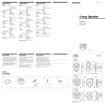
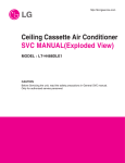
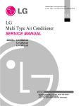
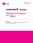
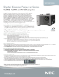
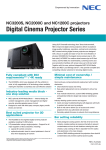
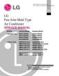
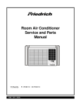
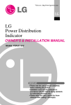
http://biz.lgservice.com
Single Package Air Conditioner
SVC MANUAL(Exploded View)
MODEL : AK-H1208C00
CAUTION
Before Servicing the unit, read the safety precautions in General SVC manual.
Only for authorized service personnel.
1. Specification
Nominal Capacity
Models
Capacity
Gross Cooling Capacity
(Ton)
Net Cooling Capacity
Net Heating Capacity
Electrical Data
Power Supply
M.C.A
(with Standard Motor)
Power Input
Cooling
Heating
Cooling
Heating
Performance
Air Circulation(Nominal)
EER
SEER
COP
Sound Rating
Indoor Coil
Type
Tube Size(O.D)
Rows / Column / FPI
Length
Face Area
Indoor Fan
Type * No. Used
Diameter
Width
Drive Type / Motor Step
No. Motors
Motor Output(Standard / Oversized)
Motor RPM(Standard / Oversized)
No. of Outdoor Units
Compressor
Type * Quantity
Model
Maker
Capacity
Motor Type
Motor Input
Oil Type
Oil Charge
Outdoor Coil
Type
Tube Size(O.D)
Rows / Column / FPI
Length
Face Area
Outdoor Fan
Type * No. Used
Diameter
Drive Type
Air Circulation
No. Motor / Motor Output(Hp)
Motor RPM
Service Valve
Liquid
Gas
Connecting Tube Liquid
Gas
Length(Standard)
Dehumidification Rate
Drain Connection Size(inch)
Refrigerant
Refrigerant Charge
Dimensions
Net Weight
Fliter
Refrigerant Control
Indoor Unit (W * H * D)
Outdoor Unit or S/Package
(W * H * D)
Indoor Unit
Outdoor Unit or S/Package
Size * No. Used
Filter Rack Thickness
kW
Btu/h
kW
Btu/h
kW
Btu/h
Ø / V / Hz
A
A
W
W
CFM
Btu/h.W
Btu/h.W
W/W
bell
mm(inch)
mm(inch)
m2(sq.ft)
mm(inch)
mm(inch)
Hp
Btu/h
W
cc
mm(inch)
mm(inch)
m2(sq.ft)
inch
CFM
Hp
mm(inch)
mm(inch)
mm(inch)
mm(inch)
mm(inch)
l/h
kg
lbs
Type
mm
inch
mm
inch
kg(lbs)
kg(lbs)
inch
Notes:
1. Capacities are based on the following conditions:
Cooling: - Indoor Temperature 27.0°C(80.6°F) DB/19.0°C(66.2°F) WB
- Outdoor Temperature 35°C(95°F) DB/24°C(75.2°F) WB
Heating: - Indoor Temperature 20.0°C(68°F) DB/15.0°C(59°F) WB
- Outdoor Temperature 7.0°C(44.6°F) DB/6.0°C(42.8°F) WB
- Level Difference of Zero
2 Single Package Air Conditioner
10
AK-H1208C00
34.6
118,000
32.8
112,000
32.8
112,000
3/380~415/50
38.2
38.2
14,400
11,600
3,700
7.78
2.83
9.20
High efficiency
9.52(3/8)
3R / 44C / 16FPI
900(35 7/16)
1.01(10.8)
Centrifugal Blower
380(14 31/32)
280(11 1/32)
Belt / 1
1
3.0 / 5.0
1,400 / 1,430
SCROLL * 2((Non Tropical)
ARA073YAA
LG
62,000
Three Phase
6,020
FVC68D(PVE)
1,800±10
High efficiency
9.52(3/8)
2R / 32C / 17FPI
1,100(43 5/16)
0.89(9.58)
Propeller * 2
23.6
Direct
3,125
2EA / 0.5
910
8.10
1
4.1/Circuit
9.04/Circuit
R-410A
Capillary Tube
2170 * 1244 * 1460
85 7/16 * 49 * 57 8/16
450(992)
925*418 * 1EA
1, 2
2. Nominal CFM : Fan operation mode with clean filter, dry coil.
3. The specification may be subject to change without prior notice for purpose of improvement.
2. Function Table
Category
Function
Air supply outlet
Airflow direction control(left & right)
Airflow direction control(up & down)
Auto swing(left & right)
Air flow
Auto swing(up & down)
Airflow steps(fan/cool/heat)
Chaos swing
Chaos wind(auto wind)
Jet cool(Power wind)
Swirl wind
Deodorizing filter
Air purifying Plasma air purifier
Prefilter(washable / anti-fungus)
Drain pump
E.S.P. control
Installation
Electric heater(operation)
High ceiling operation
Hot start
Self diagnosis
Soft dry operation
Defrost / Deicing
Reliability
High pressure switch
Low pressure switch
Phase protection
Restart delay (3-minutes)
Soft start
Test function
Auto changeover
Auto cleaning
Auto operation(artificial intelligence)
Auto restart operation
Child lock
Convenience Forced operation
Group control
Sleep mode
Timer(on/off)
Timer(weekly)
Two thermistor control
Standard wired remote controller
Deluxe wired remote controller
Individual
Simple wired remote controller
control
Wired remote controller(for hotel use)
Wireless remote controller(simple)
Wireless LCD remote control
General central controller (Non LGAP)
CAC network Dry contact
function
Network Soluation(LGAP)
PDI(power distribution indicator)
Zone control
Special
CTIE
function kit
Electro thermostat
Low ambient operation
Others
-
AK-H1208C00
1
O
Accessory
O
O
O
O
O
O
O
O
O
O
O
O
O
Accessory
O
Accessory (AUWRHS)
Accessory
Accessory
-
Note:
O : Applied, X : Not applied, – : No relation
* Option : Model name & price are different according to options, and assembled in factory with main unit.
* Accessory : Installed at field, ordered and purchased separately by the corresponding model name, supplied with separate package.
Service Manual 3
3. Fan Performance Data
CFM
2960
External Static Pressure(inches of water)
0.1
0.2
0.3
0.4
0.5
0.6
0.7
0.8
0.9
1
1.1
1.2
RPM BHP RPM BHP RPM BHP RPM BHP RPM BHP RPM BHP RPM BHP RPM BHP RPM BHP RPM BHP RPM BHP RPM BHP
-
-
3330
-
-
3700
-
-
-
-
-
-
-
-
-
-
-
-
-
-
-
-
-
-
-
-
-
-
-
-
756 1.22 777 1.27 799 1.33 822 1.39
746 1.37 763 1.42 782 1.47 802 1.53 823 1.59 845 1.66 868 1.73
747 1.56 757 1.59 770 1.63 785 1.68 801 1.73 818 1.79 837 1.86 856 1.93 877 2.01 900 2.09 923 2.19
4070
802 1.96 810 2.00 821 2.04 834 2.09 848 2.15 864 2.21 882 2.29 900 2.37 920 2.46 941 2.56 963 2.67 986 2.80
4440
875 2.54 883 2.58 894 2.63 907 2.70 921 2.77 937 2.86 954 2.96 973 3.06 993 3.18 1014 3.31 1036 3.46 1059 3.61
CFM
External Static Pressure(inches of water)
1.3
1.4
1.5
1.6
1.7
1.8
1.9
2
RPM BHP RPM BHP RPM BHP RPM BHP RPM BHP RPM BHP RPM BHP RPM BHP
2960
846 1.45 871 1.53 897 1.60 924 1.69 951 1.78 980 1.88 1009 1.99 1039 2.11
3330
892 1.81 917 1.90 943 2.00 970 2.11 997 2.22 1026 2.34 1055 2.48 1085 2.63
3700
947 2.29 972 2.40 998 2.53 1024 2.66 1052 2.80 1081 2.96 1110 3.13 1140 3.32
3Hp STANDARD MOTOR & DRIVE
5Hp OVER SIZED MOTOR & DRIVE
4070 1010 2.93 1035 3.07 1061 3.23 1088 3.40 1116 3.58 1144 3.78 1173 4.00 1204 4.24
4440 1083 3.78 1108 3.97 1134 4.17 1161 4.39 1188 4.63 1217 4.89 1246 5.17
-
-
• Fan motor heat(MBH)= 3.1 x Fan BHP
• Test Condition: ➊ Voltage : 415V
❷ Operating Mode: Fan operation mode with clean filter, dry coil, without electric heater.
• Do not operat the unit at a coling airflow that is less then 350CFM/1.2MBH.
l/s
External Static Pressure(mmaq)
2.5
5.1
7.6
10.2
12.7
15.2
17.8
20.3
22.9
25.4
27.9
30.5
RPM BkW RPM BkW RPM BkW RPM BkW RPM BkW RPM BkW RPM BkW RPM BkW RPM BkW RPM BkW RPM BkW RPM BkW
1397
-
-
-
-
-
-
-
-
-
-
1572
-
-
-
-
-
-
-
-
-
-
-
-
1746
-
-
-
-
-
-
756 0.91 777 0.95 799 0.99 822 1.04
746 1.02 763 1.06 782 1.10 802 1.14 823 1.19 845 1.24 868 1.29
747 1.17 757 1.19 770 1.22 785 1.25 801 1.29 818 1.34 837 1.38 856 1.44 877 1.50 900 1.56 923 1.63
1921
802 1.47 810 1.49 821 1.52 834 1.56 848 1.60 864 1.65 882 1.71 900 1.77 920 1.84 941 1.91 963 2.00 986 2.09
2096
875 1.89 883 1.92 894 1.96 907 2.01 921 2.07 937 2.13 954 2.21 973 2.29 993 2.38 1014 2.47 1036 2.58 1059 2.70
l/s
External Static Pressure(mmaq)
33.0
35.6
38.1
40.6
43.2
45.7
48.3
50.8
RPM BkW RPM BkW RPM BkW RPM BkW RPM BkW RPM BkW RPM BkW RPM BkW
1397
846 1.09 871 1.14 897 1.20 924 1.26 951 1.33 980 1.40 1009 1.48 1039 1.57
3Hp STANDARD MOTOR & DRIVE
5Hp OVERSIZED MOTOR & DRIVE
1572 892 1.35 917 1.42 943 1.49 970 1.57 997 1.66 1026 1.75 1055 1.85 1085 1.96
1746 947 1.71 972 1.79 998 1.88 1024 1.98 1052 2.09 1081 2.21 1110 2.34 1140 2.47
1921 1010 2.18 1035 2.29 1061 2.41 1088 2.53 1116 2.67 1144 2.82 1173 2.99 1204 3.16
2096 1083 2.82 1108 2.96 1134 3.11 1161 3.28 1188 3.45 1217 3.65 1246 3.86
-
-
• Fan motor heat(kW)= 1.22 x Fan Bkw
• Test Condition: Voltage : 415V
Operating Mode: Fan operation mode with clean filter, dry coil, without electric heater.
• Do not operat the unit at a coling airflow that is less then 165 l/s / 0.35KW
4 Single Package Air Conditioner
4. Piping Diagrams
By Pass
1.6(I.D)*1EA
Outdoor
Coil
Indoor
Coil
Pressure
Ceck Port
Pressure
Check Port
3.36(I.D)*8EA
Th3
Th1
Capillary Tube
1.2(I.D)*9EA
High Pressure
Switch
Accum
Cooling
Heating
COMP
A
Low Pressure
Switch
Th5
Capillary Tube
2.0(I.D)*3EA
Check
Valve
Capillary Tube
1.2(I.D)*9EA
3.36(I.D)*8EA
By Pass
1.6(I.D)*1EA
Pressure
Ceck Port
Pressure
Ceck Port
Th4
Capillary Tube
2.0(I.D)*5EA
Check
Valve
Th2
High Pressure
Switch
Accum
Cooling
Heating
COMP
B
Low Pressure
Switch
LOC.
Description
PCB Connector
Th
Thermistor
Th1
Thermistor Eva. For A Cycle
CN_A_CYCLE
Th2
Thermistor Eva. For B Cycle
CN_B_CYCLE
Th3
Thermistor Cond. For A Cycle
CN_A_CYCLE
Th4
Thermistor Cond. For B Cycle
CN_B_CYCLE
Th5
Outdoor Temp. Thermistor
CN_TEMP_OUT
Service Manual 5
5. Wiring Diagrams
CN_L/P
CN_COMP1
CN_THMO(11PIN)
CN_HUMID
CN_SUB(9PIN)
CN_4WAY
CN_BYPASS
CN_COMP2
CN_H/P
CN_HEATER
CN_FAN
CN_POWER
CN_ZONE
CN_B_CYCLE
CN_CS
CN_REMO
CN_CC
CN_A_CYCLE
CN_TEMP_OUT
6 Single Package Air Conditioner
CN_RETURN_AIR
CN_PHASE
6. Exploded View
435311
437212
237204
566000-2
561410
554160
137213-1
559010
561410
566000-2
554030
554160
548490
552202
552111-1
566000-1
566000-1
546810
548490
549610
552111-3
263230-1
263230-2
346810
552201
552202
263230-1
354210-1
554030
359012
263230-2
237204
342800
552111-4
552201
145610-1
354210-2
349600
145610-2
552111-2
137210
W4400
330870
263230-3
152302
137213-2
137213-3
249950
268714
566001-1
267110
566001-2
W0CZZ
566001-2
W6920
Note) * Please ensure GCSC since the replacement parts may be changed depending upon the buyer's request.
Please check the correct parts in View RPL(Replacement Part List) on GCSC.
(GCSC Website http://biz.Lgservice.com,)
Service Manual 7
P/NO : 3828A31005L
DECEMBER, 2006