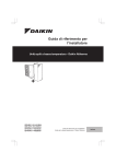
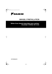
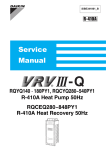
1
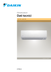
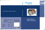
EEDEN08-720
technical data
ERHQ011-016AAW1
Altherma
Altherma
Altherma
Daikin’s unique position as a manufacturer of air conditioning equipment, compressors and refrigerants has led to its close involvement in environmental issues. For
several years Daikin has had the intention to become a leader in the
provision of products that have
limited impact on the environment. This challenge demands the
eco design and development of a
wide range of products and an energy management system, resulting in energy conservation and a
reduction of waste.
Het ISO14001 assures an effective
environmental management system in order to
help protect human health and the
environment from potential impact of our
activities, products and services and to assist in
maintaining and improving the quality of the
environment.
Daikin Europe N.V. is approved by LRQA for its
Quality Management System in accordance
with the ISO9001 standard. ISO9001 pertains
to quality assurance regarding design,
development, manufacturing as well as to
services related to the product.
“ The present publication is drawn up by way of information only
and does not constitute an offer binding upon Daikin Europe N.V..
Daikin Europe N.V. has compiled the content of this publication to
the best of its knowledge. No express or implied warranty is given
for the completeness, accuracy, reliability or fitness for particular purpose of its content and the products and services presented therein.
Specifications are subject to change without prior notice. Daikin Europe N.V. explicitly rejects any liability for any direct or indirect damage, In the broadest sense, arising from or related to the use and/or
interpretation of this publication. All content is copyrighted by Daikin
Europe N.V..”
Naamloze Vennootschap
Daikin Europe N.V. participates in the Eurovent
Certification Programme for Air Conditioners
(AC), Liquid Chilling Packages (LCP) and Fan Coil
Units (FC); the certified data of certified models
are listed in the Eurovent Directory.
Zandvoordestraat 300
B-8400 Ostend, Belgium
www.daikin.eu
BTW: BE 0412 120 336
RPR Oostende
EEDEN0 8 - 7 2 0
EEDEN08-720- 06/2008
Printed in Belgium by Goekint Graphics
Copyright © Daikin
Daikin units comply with the European
regulations that guarantee the safety of the
product.
EEDEN08-720
technical data
ERHQ011-016AAW1
Altherma
Altherma
• Outdoor units • ERHQ011-016AAW1
TABLE OF CONTENTS
ERHQ011-016AAW1
1
Features . . . . . . . . . . . . . . . . . . . . . . . . . . . . . . . . . . . . . . . . . . . . . . . . . . . . . . . . . . . . . 5
2
Specifications . . . . . . . . . . . . . . . . . . . . . . . . . . . . . . . . . . . . . . . . . . . . . . . . . . . . . . . 6
Nominal Capacity and Nominal Input . . . . . . . . . . . . . . . . . . . . . . . . . . . . . . .
Technical Specifications . . . . . . . . . . . . . . . . . . . . . . . . . . . . . . . . . . . . . . . . . . . . .
Electrical Specifications . . . . . . . . . . . . . . . . . . . . . . . . . . . . . . . . . . . . . . . . . . . . .
3
6
8
Capacity tables . . . . . . . . . . . . . . . . . . . . . . . . . . . . . . . . . . . . . . . . . . . . . . . . . . . . . 9
Cooling capacity tables
Heating capacity tables
4
6
.............................................. 9
. . . . . . . . . . . . . . . . . . . . . . . . . . . . . . . . . . . . . . . . . . . . . 10
Dimensional drawing & centre of gravity . . . . . . . . . . . . . . . . . . . . . . . 11
Dimensional drawing . . . . . . . . . . . . . . . . . . . . . . . . . . . . . . . . . . . . . . . . . . . . . . . .
Centre of gravity . . . . . . . . . . . . . . . . . . . . . . . . . . . . . . . . . . . . . . . . . . . . . . . . . . . .
11
12
5
Piping diagram . . . . . . . . . . . . . . . . . . . . . . . . . . . . . . . . . . . . . . . . . . . . . . . . . . . . . 13
6
Wiring diagram . . . . . . . . . . . . . . . . . . . . . . . . . . . . . . . . . . . . . . . . . . . . . . . . . . . . . 14
Wiring diagram . . . . . . . . . . . . . . . . . . . . . . . . . . . . . . . . . . . . . . . . . . . . . . . . . . . . . .
External connection diagram . . . . . . . . . . . . . . . . . . . . . . . . . . . . . . . . . . . . . . . .
7
8
15
Sound data . . . . . . . . . . . . . . . . . . . . . . . . . . . . . . . . . . . . . . . . . . . . . . . . . . . . . . . . . 16
Sound pressure spectrum . . . . . . . . . . . . . . . . . . . . . . . . . . . . . . . . . . . . . . . . . . .
Sound pressure spectrum quiet mode . . . . . . . . . . . . . . . . . . . . . . . . . . . . . .
17
Installation . . . . . . . . . . . . . . . . . . . . . . . . . . . . . . . . . . . . . . . . . . . . . . . . . . . . . . . . . .
19
Service space
9
14
. . . . . . . . . . . . . . . . . . . . . . . . . . . . . . . . . . . . . . . . . . . . . . . . . . . . . . . 19
Operation range . . . . . . . . . . . . . . . . . . . . . . . . . . . . . . . . . . . . . . . . . . . . . . . . . . .
• Altherma • Outdoor units
16
20
4
• Outdoor units • ERHQ011-016AAW1
1
Features
A iA n6 1u 0 a - r m 1 o r 1 o e 0 dh Q t H ulR OEA
1
1
5
• Altherma • Outdoor units
• Outdoor units • ERHQ011-016AAW1
2
Specifications
2-1 NOMINAL CAPACITY AND
NOMINAL INPUT
ERHQ011AAW1
For combination Indoor Units
indoor units +
outdoor units
Condition 1
Nominal
Capacity
ERHQ014AAW1
ERHQ016AAW1
EKHBH016AB
Heating capacity Nominal
kW
11.32
14.50
16.05
Heating PI
Nominal
kW
2.54
3.33
3.73
COP
Nominal
4.46
4.35
4.30
Heating capacity Nominal
kW
10.98
13.57
15.11
Heating PI
Nominal
kW
3.15
4.12
4.60
COP
Nominal
3.48
3.29
3.29
For combination
indoor units +
outdoor units
Indoor Units
Condition 1
Heating capacity Nominal
kW
11.32
14.50
16.05
Cooling capacity Nominal
kW
15.05
16.06
16.76
Heating PI
Nominal
kW
2.54
3.33
3.73
Cooling PI
Nominal
kW
4.44
5.33
6.06
COP
Nominal
4.46
4.35
4.30
EER
Nominal
Nominal
Capacity
3
1
2
EKHBX016AB
3.39
3.01
2.76
kW
10.98
13.57
15.11
Cooling capacity Nominal
kW
11.72
12.55
13.12
Heating PI
Nominal
kW
3.15
4.12
4.60
Cooling PI
Nominal
kW
4.22
5.00
5.65
COP
Nominal
3.48
3.29
3.29
EER
Nominal
2.78
2.51
2.32
Heating capacity Nominal
Notes
Condition 1: cooling Ta 35°C - LWE 18°C (DT = 5°C) - heating Ta DB/WB 7°C/6°C - LWC 35°C (DT = 5°C)
Condition 2: cooling Ta 35°C - LWE 7°C ( DT = 5°C ) - heating Ta DB/WB 7°C/6°C - LWC 45°C ( DT = 5°C )
2-2
TECHNICAL SPECIFICATIONS
Casing
ERHQ011AAW1
Colour
Unit
Packing
ERHQ016AAW1
Ivory white
Material
Dimensions
ERHQ014AAW1
Painted galvanised steel plate
Height
mm
Width
mm
900
1,345
900
900
Depth
mm
320
320
320
Height
mm
Width
mm
980
1,524
980
980
Depth
mm
420
420
420
Weight
Unit
kg
108 (ERHQ*W1*)110 (ERHQ*W18*)
Packed Unit
kg
120 (ERHQ*W1*)122 (ERHQ*W18*)
Packing
Material
EPS
Carton
Wood
PP (Straps)
Weight
Heat
Exchanger
Dimensions
Length
kg
12
12
12
mm
857
857
857
2
2
2
mm
1.4
1.4
1.4
5
1.131
5
1.131
5
1.131
60
60
Nr of Rows
Fin Pitch
Nr of Passes
Face Area m²
Nr of Stages
60
Tube type
Fin
Hi-XSS(8)
Type
WF fin
Treatment
Fan
Anti-corrosion treatment (PE)
Type
Propeller
Quantity
2
Discharge direction
Motor
2
2
Horizontal
Quantity
2
Model
2
2
Brushless DC motor
• Altherma • Outdoor units
6
• Outdoor units • ERHQ011-016AAW1
2
2-2
Specifications
TECHNICAL SPECIFICATIONS
Motor
1
2
Fan
ERHQ011AAW1
ERHQ014AAW1
8
8
8
rpm
760
760
760
Cooling
rpm
780
780
780
Output
W
70
70
70
Speed
(nominal)
Steps
Motor
Heating
Drive
Compressor
Direct drive
Quantity
Motor
1
Model
W
2,200
Starting Method
Cooling
Sanitary water
Sound Level
(nominal)
Refrigerant
Inverter driven
Crankcase W
Heater
33
33
33
Min
°CWB
-20
-20
-20
Max
°CWB
35
35
35
Min
°CDB
10
10
10
Max
°CDB
46
46
46
-20
Min
°CDB
-20
-20
Max
°CDB
43
43
43
Sound
Power
dBA
64
64
66
Sound
Pressure
dBA
51
51
52
Sound
Power
dBA
64
66
69
Sound
Pressure
dBA
50
52
54
Heating
Sound
Pressure
dBA
42
42
43
Cooling
Sound
Pressure
dBA
45
45
46
Heating
Cooling
Sound Level
(Night quiet)
Type
R-410A
Charge
kg
2.95
Control
Refrigerant Oil
Type
Piping
connections
Liquid (OD)
1
l
Quantity
1
1.0
1.0
1
1
1
Flare connection
Diameter
(OD)
mm
Quantity
9,52
1
Type
1
1
Flare connection
Diameter
(OD)
mm
Quantity
15,9
3
Type
3
3
Hole
Diameter
(OD)
mm
Quantity
26
1
Type
Piping Length
1
1.0
Type
Drain
2.95
Daphne FVC68D
Charged Volume
Gas
2.95
Expansion valve(electronic type)
Nr of Circuits
26
26
1
1
Hole
Diameter
(OD)
mm
Minimum
18
18
18
m
5
5
5
Maximum m
75
75
75
Equivalent m
95
95
95
Chargeless m
10
10
10
Additional Refrigerant Charge
kg/m
Installation
Maximum m
height difference
See installation manual outdoor unit 4PW42025-1
30
Heat Insulation
7
1
Hermetically sealed scroll compressor
Motor
Output
Heating
1
JT1G-VDYR@S
Type
Operation
Range
ERHQ016AAW1
30
Both liquid and gas pipes
• Altherma • Outdoor units
30
• Outdoor units • ERHQ011-016AAW1
2
2-2
Specifications
TECHNICAL SPECIFICATIONS
ERHQ011AAW1
ERHQ014AAW1
Defrost Method
Pressure equalising
Defrost Control
Sensor for outdoor heat exchanger temperature
Capacity Control Method
ERHQ016AAW1
Inverter controlled
Safety Devices
1
High pressure switch
Fan motor thermal protector
2
Fuse
Standard
Accessories
Item
3
Tie-wraps
Quantity
2
Item
2
2
Installation manual
Quantity
1
Notes
1
1
The sound pressure level is measured via a microphone at a certain distance from the unit. It is a relative value
depending on the distance and acoustic environment. Refer to sound spectrum drawing for more information.
Down to 3m with recharging of the outdoor unit. Refer to the installation manual of the outdoor unit.
Conditions: Ta DB/WB 7°C/6°C - LWC 35°C ( DT = 5°C)
Conditions: Ta 35°C - LWE 7°C ( DT = 5°C)
2-3
ELECTRICAL SPECIFICATIONS
Power Supply
W1
Phase
3N~
ERHQ016AAW1
Frequency
Hz
50
50
50
Voltage
V
400
400
400
Minimum
V
-10%
Maximum V
+10%
Nominal
Heating
running current (A)
(RLA)
A
Maximum
running
Current
Heating
A
13.5 (ERHQ*W1*) / 14 (ERHQ*W18*)
Cooling
A
13.5 (ERHQ*W1*) / 14 (ERHQ*W18*)
Recomended fuses
Wiring
connections
ERHQ014AAW1
Name
Voltage range
Current
ERHQ011AAW1
For Power
Supply
A
5.8
20
5.8
20
Remark
See installation manual outdoor unit 4PW42025-1
For connection Remark
with indoor
See installation manual outdoor unit 4PW42025-1
Power Supply Intake
5.8
20
Outdoor unit only
Notes
Conditions: Ta DB/WB 7°C/6°C - LWC 35°C (DT = 5°C)
• Altherma • Outdoor units
8
• Outdoor units • ERHQ011-016AAW1
3
Capacity tables
3-1
Cooling capacity tables
ERHQ011-016AAW1
Maximum Cooling Capacity
Model
1
Tamb
LWE [°C]
20
CC [kW]
25
PI [kW]
CC [kW]
30
PI [kW]
CC [kW]
35
PI [kW]
CC [kW]
40
PI [kW]
CC [kW]
45
PI [kW]
CC [kW]
PI [kW]
3
3TW57912-1
SYMBOLS
CC
HC
PI
LWE
LWC
Tamb
9
NOTES
: Cooling capacity at maximum operating frequency, measured acc.
Eurovent 6/C/003-2006 (kW)
: Heating capacity at maximum operating frequency, measured acc.
Eurovent 6/C/003-2006 (kW)
: Power input (kW), measured acc. Eurovent 6/C/003-2006 (kW)
: Leaving Water Evaporator temperature (°C)
: Leaving Water Condensor temperature (°C)
: Ambient temperature (°C) RH=85%
• Altherma • Outdoor units
1
2
3
Cooling capacity
Capacity is according to Eurovent rating standard 6/C/003-2006 and valid for
chilled water range Dt = 3∼8°C
Heating capacity
Capacity is according to Eurovent rating standard 6/C/003-2006 and valid for
chilled water range Dt = 3∼8°C
Power input
Power input is total of indoor and outdoor unit, except the circulation pump;
according to Eurovent rating standard 6/C/003-2006.
Pump power input to be added = 90 W (according EN14511).
• Outdoor units • ERHQ011-016AAW1
3
Capacity tables
3-2
Heating capacity tables
3
ERHQ011-016AAW1
Maximum Heating Capacity (Peak values)
Model
LWC [°C]
Tamb
30
CC [kW]
35
PI [kW]
CC [kW]
40
PI [kW]
CC [kW]
45
PI [kW]
CC [kW]
50
PI [kW]
CC [kW]
55
PI [kW]
CC [kW]
PI [kW]
1
3
Maximum Heating Capacity (integrated values*)
Model
LWC
Tamb
30
HC
35
PI
HC
40
PI
HC
45
PI
HC
50
PI
HC
55
PI
HC
PI
3TW57912-1
SYMBOLS
CC
HC
PI
LWE
LWC
Tamb
NOTES
: Cooling capacity at maximum operating frequency, measured acc.
Eurovent 6/C/003-2006 (kW)
: Heating capacity at maximum operating frequency, measured acc.
Eurovent 6/C/003-2006 (kW)
: Power input (kW), measured acc. Eurovent 6/C/003-2006 (kW)
: Leaving Water Evaporator temperature (°C)
: Leaving Water Condensor temperature (°C)
: Ambient temperature (°C) RH=85%
• Altherma • Outdoor units
1
2
3
Cooling capacity
Capacity is according to Eurovent rating standard 6/C/003-2006 and valid for
chilled water range Dt = 3∼8°C
Heating capacity
Capacity is according to Eurovent rating standard 6/C/003-2006 and valid for
chilled water range Dt = 3∼8°C
Power input
Power input is total of indoor and outdoor unit, except the circulation pump;
according to Eurovent rating standard 6/C/003-2006.
Pump power input to be added = 90 W (according EN14511).
10
• Outdoor units • ERHQ011-016AAW1
4
Dimensional drawing & centre of gravity
4-1
Dimensional drawing
ERHQ011-016AAW1
1.
2.
3.
4.
5.
6.
7.
8.
Hole for anchor bolt 4-M12
1
Gas pipe connection J15.9 flare
Liquid connection pipe "9.5 flare
Service port (in the unit)
Electronic connection and grounding terminal MS (in switch box)
Refrigerant piping intake
Power supply wiring intake (knock hole J34)
Control wiring intake (knock hole J27)
Drain outlet
4
4TW57914-1
11
• Altherma • Outdoor units
• Outdoor units • ERHQ011-016AAW1
4
Dimensional drawing & centre of gravity
4-2
Centre of gravity
3
ERHQ011-016
1
4
4TW57919-5
• Altherma • Outdoor units
12
• Outdoor units • ERHQ011-016AAW1
5
Piping diagram
ERHQ011-016AAW1
1
5
R1T
R2T
R3T
R4T
R5T
R6T
S1NPH
Y1E
E1HC
Y1S
Y3S
S1PH
M*F
M*C
: Thermistor (Air)
: Thermistor (discharge)
: Thermistor (Suction)
: Thermistor (Liquid 1)
: Thermistor (middle)
: Thermistor (Liquid 2)
: Pressure sensor
:
: Crankcase heater
: 4-way valve
: Injection valve
: High pressure switch
: Fan motor
:Compressor
filter (strainer)
filter (strainer)
Heat exchanger
Distributor
Capillary tube
Service port
5/16″
Field piping J 9.5 C 1220T-0
Field piping J15.9 C 1220T-0
Accumulator
Indoor unit
Outdoor unit
Stop valve
(with service port 5/16’ flare)
13
• Altherma • Outdoor units
Heating
Cooling
3TW57915-1A
• Outdoor units • ERHQ011-016AAW1
6
Wiring diagram
6-1
Wiring diagram
3
ERHQ011-016AAW1
EKBPHT16Y
Only for
*RHQ01*AAW1
Power supply
3N∼
400V
50Hz
Only for *RHQ01*AAW18
Indoor
Outdoor
Reactor terminal position
Note
Notes:
1 This wiring diagram only applies to the outdoor unit
2 L: Live, N: Neutral, g: Field wiring
3 D : Terminal
strip
F : Connector
GM: Connection
R : Protective earth
(screw)
: Connector
p : Noiseless earth
G : Terminal
4 Refer to the optional manual, for connection wiring to X6A and X77A.
5 Refer to the ’wiring diagram sticker’ (on the back of front plate) on how to use
BS1-BS4 and DS1 switch.
6 Do not operate the unit by short-circuiting protection device S1PH
7 Colors: BLK: black, RED: red, BLU: blue, WHT: white, YLW: yellow, ORG: orange,
BRN: brown, GRN: green
8 Confirm the method of setting the selector switches (DS1) by service manual.
Factory setting of all switches: ’Off’
9
: Option
: Wiring dependent on model
Compressor terminal
position
A1P
A2P
A3P
BS1∼BS4
C1∼C4
DS1
E1HC
E1H
E1H
F1U
F2U
F3U
F4U
F5U
F6U
F7U
F8U, F9U
HAP (A1P)
HAP (A2P)
HAP (A1P)
K1M-K2M
K1R (A1P)
K1R (A2P)
K2R (A1P)
K3R (A1P)
L1R∼L3R
L4R
M1C
M1F
M2F
PS
R1∼R4
R1T
R2T
R3T
R4T
R5T
R10T
S1NPH
S1PH
V1R∼V2R
V3R
X1M
Y1E
Y1S
Y3S
Z1C∼Z9C
Z1F∼Z4F
Q1DI
Optional connector
X6A
X77A
X1Y
Printed circuit board (Main)
Printed circuit board (INV)
Printed circuit board (Noise filter)
Push button switch
Capacitor
DIP switch
Crankcase heater
Bottomplate heater
Fuse (31.5A 250V)
Fuse (31.5A 250V)
Fuse (T 6.3A / 250V)
Fuse (T 6.3A / 250V)
Fuse (T 6.3A / 250V)
Fuse (T 6.3A / 250V)
Fuse (T 5.0A / 250V)
Fuse (F 1.0A / 250V)
Pilot lamp (Service monitor-green)
Pilot lamp (Service monitor-green)
Pilot lamp (Service monitor-orange)
Magnetic contactor
Magnetic relay (Y1S)
Magnetic relay
Magnetic relay (Y2S)
Magnetic relay (E1HC)
Reactor
Reactor (For outdoor fan motor)
Motor (Compressor)
Motor (Fan) (upper)
Motor (Fan) (lower)
Switching power supply
Resistor
Thermistor (Air)
Thermistor (Suction)
Thermistor (Heat exchanger)
Thermistor (Heat exchanger middle)
Thermistor (liquid)
Thermistor (Fin)
Pressure sensor
Pressure switch (high)
Power module
Diode module
Terminal strip
Electronic expansion valve
Solenoid valve (4 way valve)
Solenoid valve
Noise filter
Noise filter
Earth leakage protector
1
6
Connector
Connector
Connector
Reactor box A
El. comp. Assy Front
arrow A
arrow B
2TW57916-1B
• Altherma • Outdoor units
14
• Outdoor units • ERHQ011-016AAW1
6
Wiring diagram
6-2
External connection diagram
EKHB-A
Standard parts
Power supply
1
6
For more details please check unit wiring
diagram
Outdoor unit
3 core
Unit power supply: 230V + earth
X1M:L-N-Earth
Backup heater power supply (3/6/9kW): 400V or
230V + earth
Optional power supply
X2M:1-2-3-Earth
Booster heater power supply (3kW): 400V or 230V
+ earth
3 or 4 core
3 core
Optional parts
4 core
Field supply
X1M:9-10-11-Earth
Sanitary tank
Room thermostat
Power supply booster
heater
Q2L - Clixon booster
heater
R5T - Thermistor water
temperature
4 core
5 core
230V or 400V
A3P (optional)
X1M:7-8-Earth
NO valve:
2 core
NC valve:
2 core
2 core
Signal
Thermistor cable
Note: min. distance
to power cable =
3cm
2 way valve
M2S (EKHBX Units)
for cooling mode
3 way valve
M3S (when EKSWW is installed)
selection sanitary-floorheating
Indoor unit
User interface
3TW56719-6
15
• Altherma • Outdoor units
• Outdoor units • ERHQ011-016AAW1
7
Sound data
7-1
Sound pressure spectrum
3
ERHQ016AAW1*
COOLING
Sound pressure level (dB)
ERHQ014AAW1*
COOLING
Sound pressure level (dB)
Sound pressure level (dB)
ERHQ011AAW1*
COOLING
Octave band center frequency (Hz)
Octave band center frequency (Hz)
1
7
Octave band center frequency (Hz)
Notes:
1
2
3
4
Data is valid at free field condition (measured in a semi-anachoic room)
dBA = A-weighted sound power level (A-scale according to IEC)
Reference acoustic pressure 0dB = 20μPa
If sound is measured under actual installation conditions, the measured
value will be higher due to environmental noise and sound reflections.
Measuring location (discharge side)
3TW57919-1
ERHQ016AAW1*
HEATING
Sound pressure level (dB)
ERHQ014AAW1*
HEATING
Sound pressure level (dB)
Sound pressure level (dB)
ERHQ011AAW1*
HEATING
Octave band center frequency (Hz)
Octave band center frequency (Hz)
Octave band center frequency (Hz)
Notes:
1
2
3
4
Data is valid at free field condition (measured in a semi-anachoic room)
dBA = A-weighted sound power level (A-scale according to IEC)
Reference acoustic pressure 0dB = 20μPa
If sound is measured under actual installation conditions, the measured
value will be higher due to environmental noise and sound reflections.
Measuring location (discharge side)
3TW57919-2
• Altherma • Outdoor units
16
• Outdoor units • ERHQ011-016AAW1
7
Sound data
7-2
Sound pressure spectrum quiet mode
Octave band center frequency (Hz)
ERHQ016AAW1*
HEATING
Sound pressure level (dB)
7
Sound pressure level (dB)
1
ERHQ014AAW1*
HEATING
Sound pressure level (dB)
ERHQ011AAW1*
HEATING
Octave band center frequency (Hz)
Octave band center frequency (Hz)
Notes:
1
2
3
4
Data is valid at free field condition (measured in a semi-anachoic room)
dBA = A-weighted sound power level (A-scale according to IEC)
Reference acoustic pressure 0dB = 20μPa
If sound is measured under actual installation conditions, the measured
value will be higher due to environmental noise and sound reflections.
Measuring location (discharge side)
3TW57919-4
17
• Altherma • Outdoor units
• Outdoor units • ERHQ011-016AAW1
7
Sound data
7-2
Sound pressure spectrum quiet mode
3
ERHQ016AAW1*
COOLING
Sound pressure level (dB)
Sound pressure level (dB)
ERHQ014AAW1*
COOLING
Sound pressure level (dB)
ERHQ011AAW1*
COOLING
Octave band center frequency (Hz)
Octave band center frequency (Hz)
1
7
Octave band center frequency (Hz)
Notes:
1
2
3
4
Data is valid at free field condition (measured in a semi-anachoic room)
dBA = A-weighted sound power level (A-scale according to IEC)
Reference acoustic pressure 0dB = 20μPa
If sound is measured under actual installation conditions, the measured
value will be higher due to environmental noise and sound reflections.
Measuring location (discharge side)
3TW57919-3
• Altherma • Outdoor units
18
• Outdoor units • ERHQ011-016AAW1
8
Installation
8-1
Service space
ERHQ011-016
A. Non stacked installation
Legend
1
Unit: mm
Suction side obstacle
8
Discharge side obstacle
Left side obstacle
Right side obstacle
Top side obstacle
Obstacle is present
1
2
In these cases, close the bottom of
the installation frame to prevent
discharged air from being
bypassed.
In these cases, only 2 units can be
installed.
This situation is not allowed.
Figures between ( ) indicate the dimensions
only for the 100-125-140 class models.
B. Stacked installation
1. Obstacles exist in front of the outlet side
2. Obstacles exist in front of the air inlet
Do not stack more than one unit.
About 100mm is required as the dimension for laying the upper outdoor unit’s drain pipe.
Get the portion A sealed so that air from the outlet does not bypass.
C. Multiple-row installation
1. Installation of one unit per row
2. Installing multiple units (2 units or more) in lateral
connection per row
Relation of dimensions of H, A, and L are shown in the
table below.
L≤H
H<L
L
0 < L ≤ 1/2 H
1/2 H < L
Installation impossible
A
150 (250)
200 (300)
3TW26739-4
19
• Altherma • Outdoor units
• Outdoor units • ERHQ011-016AAW1
9
Operation range
3
ERHQ011-016AAW1
Outdoor temp. (°CDB)
1
Cooling mode
9
Leaving evaporator
Water temperature (°C)
6
Outdoor temp. (°CDB)
Units with optional back up heater
Heating mode
operation possible, but no guarantee of capacity
(if outdoor temperature < -25°C unit will stop)
ERHQ_W18 units include special equipment (insulation heater sheet, à) to
ensure good operation in areas where low ambient temperature can
occur together with high humidity conditions. In such conditions the
ERHQ_W1 models may experience problems with severe ice build up on
the aircooled coil. In case such conditions are expected, the ERHQ-W18
must be installed instead. These models contain countermeasures
(insulation, heater sheet, à) to prevent freeze up.
leaving condensor
Water temperature (°C)
Domestic hot water mode
Outdoor temp. (°CDB)
Booster heater operation only
Water temperature domestic hot
water tank (C°)
4TW57913-1A
• Altherma • Outdoor units
20