1
ESIE08-01
Service Manual
Altherma
- Outdoor unit
- ERHQ011~016AAV3*
- ERHQ011~016AAW1*
- Hydro-box
- EKHBH(X)0016***
- Domestic hot water tank
- EKSWW150~300V3/Z2
- EKSWWU150~300V3
- EKHWS150~300V3/Z2
- EKHWSU150~300V3/Z2
- EKHWE150~300V3/Z2
- Remote Alarm / Operation signal
- EKRP1HB
- Solar Kit
- EKSOLHWAV1
- Altherma Room thermostat
- EKRTW
- EKRTR
- EKRTETS
ESIE08-01
1
Introduction
1
1.1
1.2
1.3
1.4
About This Manual ..................................................................................
Safety Cautions.......................................................................................
Combination Overview ............................................................................
Precautions on handling new refrigerants...............................................
i-i
i-ii
i-vii
i-ix
Part 1
System Outline
1
2
3
General Outline: Altherma
1.1
1.2
1.3
1.4
1.5
1.6
1.7
1.8
1.9
1.10
1.11
1.12
1.13
1.14
1.15
1.16
1.17
What Is in This Chapter? ........................................................................
ERHQ011~016AAV3: Outlook and Dimensions .....................................
ERHQ011~016AAW1: Outlook and Dimensions ....................................
EKHBH016A***: Outlook and Dimensions ..............................................
EKHBX016A***: Outlook and Dimensions ..............................................
EKSWW150~300V3/Z2: Outlook and Dimensions - Service Space.......
EKHWS150~300*V3/Z2: Outlook and Dimensions - Service Space ......
EKHWE150~300V3/Z2: Outlook and Dimensions - Service Space........
EKSWWU150~300V3: Outlook and Dimensions - Service Space .........
EKHWSU150~300V3: Outlook and Dimensions - Service Space ..........
EKSOLHWAV1~EKHWS*: Outlook and Dimensions - Service Space ...
EKSOLHWAV1~EKHWSU*: Outlook and Dimensions - Service Space
EKRTR / EKRTW: Outlook and Dimensions...........................................
ERHQ011~016AAV3*/W1*: Installation and Service Space...................
EKHBH(X)0016AA***: Installation and Service Space ...........................
Physical Limitations and Limits of Operation .........................................
EKHBDP - Drainpan Kit Necessity..........................................................
1-3
1-4
1-5
1-7
1-9
1-11
1-13
1-15
1-17
1-19
1-21
1-22
1-25
1-26
1-28
1-29
1-31
2.1
2.2
2.3
2.4
What Is in This Chapter? ........................................................................
1-33
Technical and Electrical Specifications for ERHQ011~016AAV3 ...........
1-34
Technical and Electrical Specifications for ERHQ011~016AAW1 ..........
1-37
Technical and Electrical Specifications for EKHBH016AA*** & EKHBX016AA***
and EKHBH016AB*** & EKHBX016AB*** ..............................................
1-40
Technical and Electrical Specifications for EKSWW150~300V3/Z2 &
EKHWS150~300*V3/Z2..........................................................................
1-43
Technical and Electrical Specifications for EKSWWU150~300V3 &
EKHWSU150~300*V3 ............................................................................
1-44
Technical and Electrical Specifications for EKSOLHWAV1 ....................
1-45
Technical and Electrical Specifications for EKRTW / EKRTR.................
1-46
Specifications
2.5
2.6
2.7
2.8
Table of Contents
1
4
5
ESIE08-01
1
3
Functional Diagrams
3.1
3.2
3.3
3.4
3.5
4
4
Piping Diagrams
4.1
4.2
4.3
4.4
4.5
4.6
3
5
6
1-59
1-60
1-61
1-64
1-66
1-68
What Is in This Chapter? .........................................................................
Switch Box Layout for ERHQ011~016AAV3 ...........................................
Switch Box Layout for ERHQ011~016AAW1 ..........................................
Switch Box Layout for EKHBH(X)016A*** ...............................................
Switch Box Layout for EKHBH(X)016AB*** .............................................
Switch Box Layout for EKSWW***V3/Z2 .................................................
Switch Box Layout for EKHWS***V3/Z2 ..................................................
Switch Box Layout for EKSWWU***V3 ....................................................
Switch Box Layout for EKHWSU***V3.....................................................
Switch Box Layout for EKHWE***V3/Z2 ..................................................
1-71
1-72
1-73
1-75
1-76
1-78
1-79
1-80
1-81
1-82
What Is in This Chapter? .........................................................................
Wiring Diagram for EKHBH(X)016AA3V3................................................
Wiring Diagram for EKHBH(X)016AB3V3................................................
Wiring Diagram for EKHBH(X)016AA6V3................................................
Wiring Diagram for EKHBH(X)016AB6V3................................................
Wiring Diagram for EKHBH(X)016AA6T1/9T1.........................................
Wiring Diagram for EKHBH(X)016AB6T1/9T1.........................................
Wiring Diagram for EKHBH(X)016AA6WN/9WN .....................................
Wiring Diagram for EKHBH(X)016AB6WN/9WN .....................................
Wiring Diagram for ERHQ011~016AAV3*...............................................
Wiring Diagram for ERHQ011~016AAW1*..............................................
Wiring Diagram for EKSWW150~300V3/Z2 ............................................
Wiring Diagram for EKHWS150~300*V3/Z2 & EKHWSU150~300*V3....
Wiring Diagram for EKSWWU150~300V3...............................................
Wiring Diagram for EKHWE150~300*V3/Z2............................................
Wiring Diagram for EKRTR / EKRTW......................................................
1-85
1-86
1-88
1-90
1-92
1-94
1-96
1-98
1-100
1-102
1-104
1-106
1-108
1-110
1-112
1-114
Wiring Diagrams
6.1
6.2
6.3
6.4
6.5
6.6
6.7
6.8
6.9
6.10
6.11
6.12
6.13
6.14
6.15
6.16
2
What Is in This Chapter? .........................................................................
Piping Diagram for ERHQ011~016AAV3(8) ............................................
Piping Diagram for ERHQ011~016AAW1(8) ...........................................
Piping Diagram for EKHBH(X)016A*** ...................................................
Piping Diagram for EKSWWU150~300V3 ...............................................
Piping Diagram for EKSOLHWAV1 .........................................................
Switch Box Layout
5.1
5.2
5.3
5.4
5.5
5.6
5.7
5.8
5.9
5.10
5
What Is in This Chapter? ......................................................................... 1-49
Complete System (ERHQ011~016AAV3 + EKHBH/X016AA*** + EKSWW)1-50
Complete System (ERHQ011~016AAW1 + EKHBH/X016AB + EKHWS(U)/
EKHWE) .................................................................................................. 1-52
Electrical Connection Diagram ................................................................ 1-55
Pipe Connection Diameters ..................................................................... 1-56
Table of Contents
ESIE08-01
7
PCB Layout
1
7.1
7.2
7.3
7.4
What Is in This Chapter? ........................................................................
PCB Layout for ERHQ011~016AAV3 .....................................................
PCB Layout for ERHQ011~016AAW1*...................................................
PCB Layout for EKHBH(X)016 ...............................................................
1-117
1-118
1-124
1-130
Part 2
Functional Description
1
1.1
1.2
1.3
1.4
1.5
1.6
1.7
1.8
1.9
1.10
1.11
1.12
1.13
2
What Is in This Chapter? ........................................................................
Function of Thermistors ..........................................................................
Forced Operating Mode (Emergency Operation)....................................
Simulated Operation Function ................................................................
Restart Standby ......................................................................................
Automatic Restart ...................................................................................
Forced Thermostat OFF .........................................................................
Test Run Control.....................................................................................
4-way Valve Control ................................................................................
Pump Down And Forced Defrost Operation ...........................................
Defrost Operation....................................................................................
Freeze Prevention Function ....................................................................
Crankcase Heater Control ......................................................................
2-3
2-4
2-6
2-8
2-9
2-10
2-11
2-12
2-13
2-14
2-15
2-17
2-18
Hydro-box Functional Concept
2.1
2.2
2.3
2.4
2.5
2.6
2.7
2.8
2.9
2.10
2.11
3
3
General Functionality
What Is in This Chapter? ........................................................................
Hydro-box Pump Blockage Prevention Control ......................................
Hydro-box Pump Operation Control........................................................
Defrost control.........................................................................................
Cooling operation ....................................................................................
Heating operation....................................................................................
H/P hot water heating operation .............................................................
H/P hot water heating priority function ....................................................
Booster heater operation ........................................................................
Backup heater operation .........................................................................
Emergency operation ..............................................................................
2-19
2-20
2-21
2-23
2-24
2-25
2-26
2-27
2-28
2-29
2-31
Outdoor Unit Functional Concept
3.1
3.2
3.3
3.4
3.5
Table of Contents
What Is in This Chapter? ........................................................................
Function Outline ......................................................................................
Frequency Regulating Functions ...........................................................
Expansion Valve Regulating Functions .................................................
Outdoor Unit Fan Speed Control ...........................................................
2-33
2-34
2-37
2-52
2-56
3
4
5
ESIE08-01
1
Part 3
Troubleshooting
1
1.1
1.2
1.3
1.4
1.5
1.6
1.7
1.8
1.9
1.10
3
4
Troubleshooting
2
2.7
2.8
3
What Is in This Chapter? ......................................................................... 3-41
“A1” Malfunctioning Hydro-box PCB ......................................................... 3-42
“C4, 81, 80, HC” Thermistor or Related Abnormality (Hydro-box)................ 3-43
“7H” Hydro-box ......................................................................................... 3-44
“8H” Hydro-box: Outlet water temperature too high (> 65°C)................... 3-47
“AA” Hydro-box: Open thermal protector / fuse of backup heater or booster heater.............................................................................................................. 3-48
“C0” Hydro-box: Flow switch failure.......................................................... 3-51
3-52
“EC” Hydro-box: Domestic hot water tank temperature too high (> 89°C)
Error Codes: Outdoor Units
3.1
3.2
3.3
3.4
3.5
3.6
3.7
3.8
3.9
3.10
3.11
3.12
3.13
3.14
3.15
3.16
3.17
3.18
3.19
3.20
4
3-3
3-4
3-5
3-24
3-25
3-26
3-29
3-34
3-38
3-39
Error Codes: Hydro-box
2.1
2.2
2.3
2.4
2.5
2.6
5
What Is in This Chapter? .........................................................................
General Troubleshooting Flowchart.........................................................
Overview of General Problems ................................................................
Procedure of Self-Diagnosis by Remote Controller .................................
Fault-diagnosis by Remote Controller......................................................
Fault-diagnosis manual reset in the memory ...........................................
Fault Diagnosis by LED ...........................................................................
Overview of Error Codes .........................................................................
Overview of the Outdoor Safety Devices .................................................
Overview of the Hydro-box Safety Devices .............................................
What Is in This Chapter? ......................................................................... 3-53
“E1” Outdoor Unit PCB Abnormality.......................................................... 3-54
“E3”Abnormal High Pressure (Detected by the HPS)............................... 3-55
“E4” Actuation of Low Pressure Sensor ................................................... 3-57
“E5” Compressor Motor Lock................................................................... 3-60
“E7” Malfunction of Outdoor Unit Fan Motor............................................. 3-62
“E9” Malfunction of Electronic Expansion Valve....................................... 3-65
“F3” Malfunctioning in Discharge Pipe Temperature ................................ 3-68
“H3” Malfunctioning HPS System ............................................................. 3-70
“H9, J3, J5, J6, J7, J8” Thermistor or Related Abnormality (Outdoor Unit)
3-72
“J1” Malfunction of Pressure Sensor ........................................................ 3-73
“L1” Faulty Outdoor PC Board .................................................................. 3-75
“L4” Radiation Fin Temperature Increased .............................................. 3-77
“L5” DC Output Overcurrent (Instantaneous)........................................... 3-79
“L8” DC Output Overcurrent (Instantaneous)........................................... 3-81
“L9” Stall Prevention (Time Lag) .............................................................. 3-83
“LC” Malfunction of Transmission system (Between Control PCB and Inverter
PCB) ........................................................................................................ 3-85
“P1” Open Phase or Power Supply Voltage Imbalance ........................... 3-87
“P4” Malfunction of Radiator Fin Temperature Thermistor ...................... 3-88
“PJ” Malfunction of Radiator Fin Temperature Thermistor....................... 3-89
Table of Contents
ESIE08-01
4
Error Codes: System Malfunctions
4.1
4.2
4.3
4.4
4.5
4.6
4.7
5
1
What Is in This Chapter? ........................................................................
3-91
“U0” Gas Shortage (Malfunction).............................................................
3-92
“U2” Abnormal Power Supply Voltage.....................................................
3-94
“U4”, “UF” Malfunction of Transmission between Hydro-box and Outdoor Unit
3-96
“UF” Malfunction of Transmission between Hydro-box and Outdoor Unit or Gas
Shortage .................................................................................................
3-99
“U5” Malfunction of Transmission between Hydro-box and Remote Controller
3-101
“UA” Malfunctioning Field Setting Switch................................................. 3-102
3
Additional Checks for Troubleshooting
5.1
5.2
5.3
5.4
5.5
5.6
5.7
5.8
5.9
5.10
5.11
5.12
5.13
5.14
5.15
What Is in This Chapter? ........................................................................
Check No.1 - Outdoor unit: Checking the Installation Condition .............
Check No.2 - Outdoor Unit: Checking the Expansion Valve ...................
Check No.3 - Checking the Thermistors .................................................
Check No.4 - Resistance Conversion Table (Ambient, Coil, Fin) ...........
Check No.5 - Resistance Conversion Table (Discharge Pipe Sensor) ...
Check No.6 - Evaluation of Abnormal High Pressure .............................
Check No.7 - Evaluation of Abnormal Low Pressure ..............................
Check No.8 - Clogged Points..................................................................
Check No.9 - Outdoor Unit: Fan Motor Signal Line ................................
Check No.10 - Outdoor unit: Fan Speed Pulse.......................................
Check No.11 - Outdoor unit: Check for Power Transistor.......................
Check No.13 - Check for Inadequate Refrigerant ...................................
Check No.14 - Check for Excessive Refrigerant Charging .....................
Check No.15 - Check for Factors Causing Wet Operation .....................
3-103
3-104
3-105
3-106
3-107
3-109
3-110
3-111
3-112
3-113
3-114
3-115
3-116
3-118
3-119
1.1
1.2
1.3
What Is in This Chapter? ........................................................................
Checks before Test Run .........................................................................
Test Run Operation (Manual) .................................................................
4-3
4-4
4-7
2.1
2.2
2.3
2.4
What Is in This Chapter? ........................................................................
Operation of the User interface Inspection / Test Operation Button .......
Overview of the Field Settings of the Hydro-box.....................................
Overview of the Field Setting on the Outdoor Unit..................................
4-9
4-10
4-11
4-29
Part 4
Commissioning and
Test Run
1
2
Pre-Test Run Checks
Field settings
Table of Contents
5
4
5
ESIE08-01
1
3
Test Run and Operation Data
3.1
3.2
3.3
Operation Range ERHQ011~016AAV3...................................................
Operation Range ERHQ011~016AAW1..................................................
External Static Pressure ..........................................................................
4-38
4-40
4-42
Part 5
Maintenance and Disassembly
3
1
Maintenance
1.1
1.2
4
2
6
5-3
5-4
Removal procedure: outdoor unit ERHQ011~016AAV3
2.1
2.2
2.3
2.4
2.5
2.6
2.7
2.8
2.9
5
What Is in This Chapter? .........................................................................
Maintenance ............................................................................................
What Is in This Chapter? .........................................................................
Removal of Outside Panels .....................................................................
Removal of Propeller Fan and Fan Motor................................................
Removal of Switch Box ............................................................................
Removal of PC Board ..............................................................................
Removal of Pressure Sensor, Electronic Expansion Valve, and Others..
Removal of Thermistor ............................................................................
Removal of Four Way Valve ....................................................................
Removal of Compressor ..........................................................................
5-5
5-6
5-7
5-8
5-9
5-10
5-11
5-12
5-13
Table of Contents
ESIE08-01
Introduction
Part 0
1
Introduction
1.1
About This Manual
Target group
This service manual is intended for and should only be used by qualified engineers.
Purpose of this
manual
This service manual contains all the information you need to carry out the necessary repair and
maintenance tasks for the ALTHERMA.
Five parts
This service manual consists of an introduction, five parts and an index:
Introduction
overview
Note:
Part
See page
Part 1–System Outline
1–1
Part 2–Functional Description
2–1
Part 3–Troubleshooting
3–1
Part 4–Commissioning and Test Run
4–1
Part 5–Maintenance and Disassembly
5–1
3
4
5
The introduction contains the following topics:
Topic
See page
1.2–Safety Cautions
ii
1.3–Combination Overview
vii
1.4–Precautions on handling new refrigerants
ix
This Service Manual is about ERHQ011~016 / EKHBH(X)016***. Please refer to Service Manual
ESIE06-03 for details on ERYQ005~007 / EKHBH(X)007*** / ERHQ006~008 / EKHBH(X)008.
i
Introduction
1
1.2
ESIE08-01
Safety Cautions
Cautions and
warnings
■
Be sure to read the following safety cautions before conducting repair work.
■
The caution items are classified into “Warning” and “Caution”. The “Warning” items are especially
important since they can lead to death or serious injury if they are not followed closely. The
“Caution” items can also lead to serious accidents under some conditions if they are not followed.
Therefore, be sure to observe all the safety caution items described below.
■
About the pictograms
This symbol indicates an item for which caution must be exercised.
The pictogram shows the item to which attention must be paid.
3
This symbol indicates a prohibited action.
The prohibited item or action is shown inside or near the symbol.
This symbol indicates an action that must be taken, or an instruction.
The instruction is shown inside or near the symbol.
4
■
1.2.1
5
After the repair work is complete, be sure to conduct a test operation to ensure that the equipment
operates normally, and explain the cautions for operating the product to the customer.
Caution in Repair
Warning
Warning
Be sure to disconnect the power cable plug from the plug socket before disassembling the equipment for a repair.
Working on the equipment that is connected to a power supply can cause an
electrical shook.
If it is necessary to supply power to the equipment to conduct the repair or
inspecting the circuits, do not touch any electrically charged sections of the
equipment.
If the refrigerant gas discharges during the repair work, do not touch the discharging refrigerant gas.
The refrigerant gas can cause frostbite.
When disconnecting the suction or discharge pipe of the compressor at the
welded section, release the refrigerant gas completely at a well-ventilated
place first.
If there is a gas remaining inside the compressor, the refrigerant gas or refrigerating machine oil discharges when the pipe is disconnected, and it can
cause injury.
If the refrigerant gas leaks during the repair work, ventilate the area. The
refrigerant gas can generate toxic gases when it contacts flames.
ii
ESIE08-01
Introduction
Warning
The step-up capacitor supplies high-voltage electricity to the electrical components of the outdoor unit.
Be sure to discharge the capacitor completely before conducting repair work.
A charged capacitor can cause an electrical shock.
Do not start or stop the air conditioner operation by plugging or unplugging the
power cable plug.
Plugging or unplugging the power cable plug to operate the equipment can
cause an electrical shock or fire.
3
Caution
Caution
Do not repair the electrical components with wet hands.
Working on the equipment with wet hands can cause an electrical shock.
4
Do not clean the air conditioner by splashing water.
Washing the unit with water can cause an electrical shock.
5
Be sure to provide the grounding when repairing the equipment in a humid or
wet place, to avoid electrical shocks.
Be sure to turn off the power switch and unplug the power cable when cleaning the equipment.
The internal fan rotates at a high speed, and cause injury.
Do not tilt the unit when removing it.
The water inside the unit can spill and wet the furniture and floor.
Be sure to check that the refrigerating cycle section has cooled down sufficiently before conducting repair work.
Working on the unit when the refrigerating cycle section is hot can cause
burns.
Use the welder in a well-ventilated place.
Using the welder in an enclosed room can cause oxygen deficiency.
iii
Introduction
1
1.2.2
ESIE08-01
Cautions Regarding Products after Repair
Warning
Warning
Be sure to use parts listed in the service parts list of the applicable model and
appropriate tools to conduct repair work. Never attempt to modify the equipment.
The use of inappropriate parts or tools can cause an electrical shock, excessive heat generation or fire.
When relocating the equipment, make sure that the new installation site has
sufficient strength to withstand the weight of the equipment.
If the installation site does not have sufficient strength and if the installation
work is not conducted securely, the equipment can fall and cause injury.
Be sure to install the product correctly by using the provided standard installa- For integral units
tion frame.
only
3
Incorrect use of the installation frame and improper installation can cause the
equipment to fall, resulting in injury.
Be sure to install the product securely in the installation frame mounted on a For integral units
window frame.
only
4
If the unit is not securely mounted, it can fall and cause injury.
Be sure to use an exclusive power circuit for the equipment, and follow the
technical standards related to the electrical equipment, the internal wiring regulations and the instruction manual for installation when conducting electrical
work.
5
Insufficient power circuit capacity and improper electrical work can cause an
electrical shock or fire.
Be sure to use the specified cable to connect between the indoor and outdoor
units. Make the connections securely and route the cable properly so that
there is no force pulling the cable at the connection terminals.
Improper connections can cause excessive heat generation or fire.
When connecting the cable between the indoor and outdoor units, make sure
that the terminal cover does not lift off or dismount because of the cable.
If the cover is not mounted properly, the terminal connection section can
cause an electrical shock, excessive heat generation or fire.
Do not damage or modify the power cable.
Damaged or modified power cable can cause an electrical shock or fire.
Placing heavy items on the power cable, and heating or pulling the power
cable can damage the cable.
Do not mix air or gas other than the specified refrigerant (R-410A) in the refrigerant system.
If air enters the refrigerating system, an excessively high pressure results,
causing equipment damage and injury.
If the refrigerant gas leaks, be sure to locate the leak and repair it before
charging the refrigerant. After charging refrigerant, make sure that there is no
refrigerant leak.
If the leak cannot be located and the repair work must be stopped, be sure to
perform pump-down and close the service valve, to prevent the refrigerant gas
from leaking into the room. The refrigerant gas itself is harmless, but it can
generate toxic gases when it contacts flames, such as fan and other heaters,
stoves and ranges.
iv
ESIE08-01
Introduction
Warning
When replacing the coin battery in the remote controller, be sure to disposed
of the old battery to prevent children from swallowing it.
If a child swallows the coin battery, see a doctor immediately.
Cautions
Caution
Installation of a leakage breaker is necessary in some cases depending on the
conditions of the installation site, to prevent electrical shocks.
Do not install the equipment in a place where there is a possibility of combustible gas leaks.
3
If a combustible gas leaks and remains around the unit, it can cause a fire.
Be sure to install the packing and seal on the installation frame properly.
If the packing and seal are not installed properly, water can enter the room
and wet the furniture and floor.
1.2.3
For integral units
only
4
Inspection after Repair
5
Warning
Warning
Check to make sure that the power cable plug is not dirty or loose, then insert
the plug into a power outlet all the way.
If the plug has dust or loose connection, it can cause an electrical shock or
fire.
If the power cable and lead wires have scratches or deteriorated, be sure to
replace them.
Damaged cable and wires can cause an electrical shock, excessive heat generation or fire.
Do not use a joined power cable or extension cable, or share the same power
outlet with other electrical appliances, since it can cause an electrical shock,
excessive heat generation or fire.
v
Introduction
1
ESIE08-01
Caution
Caution
Check to see if the parts and wires are mounted and connected properly, and
if the connections at the soldered or crimped terminals are secure.
Improper installation and connections can cause excessive heat generation,
fire or an electrical shock.
If the installation platform or frame has corroded, replace it.
Corroded installation platform or frame can cause the unit to fall, resulting in
injury.
Check the grounding, and repair it if the equipment is not properly grounded.
Improper grounding can cause an electrical shock.
3
Be sure to measure the insulation resistance after the repair, and make sure
that the resistance is 1 Mohm or higher.
Faulty insulation can cause an electrical shock.
Be sure to check the drainage of the hydro-box after the repair.
Faulty drainage can cause the water to enter the room and wet the furniture
and floor.
4
5
vi
ESIE08-01
1.3
Table
Introduction
Combination Overview
The table below contains the possible combinations between hydro-box units and outdoor units of the
ALTHERMA series.
Hydro-box 1~230V
Outdoor unit
1~230V
Outdoor unit
3+N~400V
Domestic hot
water tank
1~230V
Domestic hot
water tank
2~400V
Remarks
Hydro-box 1~230V
Heating only
Reversible
Heating only
Reversible
EKHBH016AA***(1)
EKHBX016AA***(1)
EKHBH016AB***(1)
EKHBX016AB***(1)
ERHQ011AAV3(8)
0
0
0
0
ERHQ014AAV3(8)
0
0
0
0
ERHQ016AAV3(8)
0
0
0
0
ERHQ011AAW1(8
0
0
0
0
ERHQ014AAW1(8)
0
0
0
0
ERHQ016AAW1(8)
0
0
0
0
EKHWS(U)150V3(2)
0
0
0
0
EKHWS(U)200V3(2)
0
0
0
0
EKHWS(U)300V3(2)
0
0
0
0
EKHWS[E]200Z2(3)
0
0
0
0
EKHWS[E]300Z2(3)
0
0
0
0
EKHWE150V3(4)
Domestic hot
water tank
1~230V
0
0
0
0
EKHWE200V3(4)
0
0
0
0
EKHWE300V3(4)
0
0
0
0
Solarkit 1~230V
EKSOLHWAV1(5)
-
-
0
0
3
4
5
(1) *** : index for the factory mounted backup heater option 3~6V3 / 6~9T1 / 6~9WN
(2) (U) :Domestic hot water tank stainless special for UK market
(3) [E] :Domestic hot water tank enamel
(4) [E] :Domestic hot water tank enamel
(5) Solarkit :The EKSOLHWAV1can only be combined with domestic hot water tank with solarsensor
socket (EKHWS[E]******)
vii
Introduction
ESIE08-01
1
Hydro-box 1~230V
Domestic hot
water tank
1~230V
Domestic hot
water tank
2~400V
3
Domestic hot
water tank
1~230V
Domestic hot
water tank
1~230V
4
Domestic hot
water tank
1~230V
Domestic hot
water tank
2~400V
5
Remarks
Options
Heating only
Reversible
Heating only
Reversible
Solar kit
UK tank kit
(incl 2-WV)
UK tank kit
(excl 2-WV)
Seperate
2-WV
EKHBH(X)016AA***(1)
EKHBH(X)016AB***(1)
EKSOLHWAV1
EKUHWA (6)
EKUHWB (7)
EKUHW2WB (7)
EKHWS150*V3(2)
o
o
o
-
-
-
EKHWS200*V3(2)
o
o
o
-
-
-
EKHWS300*V3(2)
o
o
o
-
-
-
EKHWS200*Z2(2)
o
o
o
-
-
-
EKHWS300*Z2(2)
o
o
o
-
-
-
EKHWSU150AV3(3)
o
o
o
o
o(8)
o(8)
EKHWSU200AV3(3)
o
o
o
o
o(8)
o(8)
EKHWSU300AV3(3)
o
o
o
o
o(8)
o(8)
EKHWSU150BV3(4)
o
o
o
o(9)
o(10)
o(10)
EKHWSU200BV3(4)
o
o
o
o(9)
o(10)
o(10)
EKHWSU300BV3(4)
o
o
o
o(9)
o(10)
o(10)
EKHWE150AV3(5)
o
o
o
-
-
-
EKHWE200AV3(5)
o
o
o
-
-
-
EKHWE300AV3(5)
o
o
o
-
-
-
EKHWE200AZ2(5)
o
o
o
-
-
-
EKHWE300AZ2(5)
o
o
o
-
-
-
(1) *** : index for the factory mounted backup heater option 3~6V3 / 6~9T1 / 6~9WN
(2) :Domestic hot water tank stainless with extra connection for hot water recirculation:
■
‘A’: without 3-way valve
■
‘B’: with 3-way valve
(3) :Domestic hot water tank stainless special for UK market with extra connection for hot water
recirculation. Without 3-way valve
(4) :Domestic hot water tank stainless special for UK market with extra connection for hot water
recirculation. With 3-way valve
(5) :Domestic hot water tank enamel with extra connection for hot water recirculation. With 3-way
valve
(6) :EKUHWA is the substitute of EKUSWW. Kit contains 2-way valve (2-way valve only required in
combination with solar kit)
(7) :EKUHWB doesn't contain 2-way valve. In case solar kit is used (2-way valve is required)
EKUHW2WB has to be ordered additionally.
(8) :Combination is possible but EKUHWB & EKUHW2WB are always required (2-way valve is
required, no 3-way valve delivered with tank).
(9) :Only for connection to solar, 2-way valve is obligated.
(10) :Only for connection to solar, both EKUHWB & EKUHW2WB are required (2-way valve is
obligated).
viii
ESIE08-01
Introduction
1.4
Precautions on handling new refrigerants
1.4.1
Outline
About Refrigerant
R410A
■
Characteristics of new refrigerant, R410A
1
Performance
Almost the same performance as R22 and R407C.
2
Pressure
Working pressure is approx. 1.4 times more than R22 and R407C.
3
Refrigerant composition
Few problems in composition control, since it is a Quasi-azeotropic mixture refrigerant.
HFC units (Units using new refrigerants)
Refrigerant name
Composing
substances
Design pressure
Refrigerant oil
Ozone destruction
factor (ODP)
Combustibility
Toxicity
R407C
R410A
Non-azeotropic mixture Quasi-azeotropic mixof HFC32, HFC125 and ture of HFC32 and
HFC134a (*1)
JFC125 (*1)
4.15 Mpa (gauge pressure)
3.2 Mpa (gauge pres= 42.3 kgf/cm2
sure) = 32.6 kgf/cm2
Synthetic oil (Ether)
0
0
None
None
None
None
3
HCFC units
R22
Single-component refrigerant
2.75Mpa (gauge pressure)
= 28.0 kgf/cm2
Mineral oil (Suniso)
0.05
None
None
*1. Non-azeotropic mixture refrigerant: mixture of two or more refrigerants having different boiling
points.
*2. Quasi-azeotropic mixture refrigerant: mixture of two or more refrigerants having similar boiling
points.
*3. The design pressure is different at each product. Please refer to the installation manual for each
product.
(Reference) 1 Mpa
1 0.19716 kgf / cm2
Pressure-Enthalpy curves of HFC-32/125 (50/50wt%)
ix
4
5
Introduction
ESIE08-01
■
1
Thermodynamic characteristic of R410A
Temperature
( )
3
4
5
x
Steam pressure
(kPa)
Liquid
Vapor
Density
(kg/m3 )
Liquid
Vapor
Specific heat at constant
pressure (kJ/kgK)
Liquid
Vapor
Specific enthalpy
(kJ/kg)
Liquid
Vapor
Specific entropy
(kJ/KgK)
Liquid
Vapor
ESIE08-01
1.4.2
Introduction
Refrigerant Cylinders
Cylinder
specifications
■
The cylinder is painted refrigerant color (pink).
■
The cylinder valve is equipped with a siphon tube.
Cylinder
Siphon tube
3
Note: Refrigerant can be charged in liquid state with cylinder in upright position.
4
Caution!: Do not lay cylinder on its side during charging, since it causes refrigerant in gas state to
enter the system.
Handling of
cylinders
1
Laws and regulations
R410A is liquefied gas, and the High-Pressure Gas Safety Law must be observed in handling
them. Before using, refer to the High-Pressure Gas Safety Law.
The Law stipulates standards and regulations that must be followed to prevent accidents with
high-pressure gases. Be sure to follow the regulations.
5
2
Handing of vessels
Since R410A is high-pressure gas, it is contained in high-pressure vessels.
Although those vessels are durable and strong, careless handling can cause damage that can lead
to unexpected accidents. Do not drop vessels, let them fall, apply impact or roll them on the ground.
3
Storage
Although R410A is not flammable, it must be stored in a well-ventilated, cool, and dark place in the
same way as any other high-pressure gases.
It should also be noted that high-pressure vessels are equipped with safety devices that releases
gas when the ambient temperature reaches more than a certain level (fusible plug melts) and when
the pressure exceeds a certain level (spring-type safety valve operates).
xi
Introduction
1
1.4.3
ESIE08-01
Service Tools
R410A is used under higher working pressure, compared to previous refrigerants (R22,R407C).
Furthermore, the refrigerating machine oil has been changed from Suniso oil to Ether oil, and if oil
mixing is occurred, sludge results in the refrigerants and causes other problems. Therefore, gauge
manifolds and charge hoses that are used with a previous refrigerant (R22,R407C) can not be used
for products that use new refrigerants.
Be sure to use dedicated tools and devices.
■
Tool compatibility
Compatibility
Tool
3
HFC
R410A
HCFC
R407C
R22
Gauge manifold
Charge hose
Charging cylinder
4
Gas detector
X
X
O
O
X
5
Refrigerant recovery
device
Refrigerant piping
Do not use the same tools for R22
and R410A.
■
Thread specification differs for
R410A and R407C.
Weighting instrument used for
HFCs.
The same tool can be used for
HFCs.
To use existing pump for HFCs,
vacuum pump adaptor must be
installed.
■
■
O
O
X
Flaring tool (Clutch
type)
Torque wrench
Pipe cutter
Pipe expander
Pipe bender
Pipe assembling oil
■
■
Vacuum pump
(pump with reverse flow
preventive function)
Weighting instrument
Charge mouthpiece
Reasons for change
O
O
O
O
O
X
■
Seal material is different between
R22 and HFCs.
■
Thread specification is different
between R410A and others.
For R410A, flare gauge is
necessary.
Torque-up for 1/2 and 5/8
■
■
■
Due to refrigerating machine oil
change. (No Suniso oil can be used.)
■
Only φ19.1 is changed to 1/2H
material while the previous material is
"O".
Check your recovery device.
See the chart below.
As for the charge mouthpiece and packing, 1/2UNF20 is necessary for mouthpiece size of charge
hose.
xii
ESIE08-01
Introduction
Copper tube
material and
thickness
R407C
Pipe size
R410A
Material
Thickness
t (mm)
Material
Thickness
t (mm)
φ6.4
O
0.8
O
0.8
φ9.5
O
0.8
O
0.8
φ12.7
O
0.8
O
0.8
φ15.9
O
1.0
O
1.0
φ19.1
O
1.0
1/2H
1.0
* O: Soft (Annealed)
H: Hard (Drawn)
3
Flaring tool
4
5
Flare gauge
■
•
Specifications
Dimension A
Nominal size
A +0
-0.4
Tube O.D.
Do
Class-2 (R410A)
Class-1 (Conventional)
1/4
6.35
9.1
9.0
3/8
9.52
13.2
13.0
1/2
12.70
16.6
16.2
5/8
15.88
19.7
19.4
3/4
19.05
24.0
23.3
xiii
Introduction
ESIE08-01
■
1
•
Differences
Change of dimension A
Dimension A
For class-1: R407C
For class-2: R410A
Conventional flaring tools can be used when the work process is changed. (change of work process)
Previously, a pipe extension margin of 0 to 0.5mm was provided for flaring. For R410A air
conditioners, perform pipe flaring with a pipe extension margin of 1.0 to 1.5 mm. (For clutch type only)
3
Conventional tool with pipe extension margin adjustment can be used.
Torque wrench
4
■
•
5
Specifications
Dimension B
Nominal size
1/2
5/8
Unit:mm
Class-1
24
27
Class-2
26
29
Previous
24
27
No change in tightening torque
No change in pipes of other sizes
■
•
Differences
Change of dimension B
Only 1/2", 5/8" are extended
For class-1: R407C
For class-2: R410A
Dimension B
xiv
ESIE08-01
Introduction
Vacuum pump with
check valve
Vacuum pump adaptor
(Reverse flow preventive
vacuum adaptor)
■
Specifications
•
•
■
•
•
Discharge speed
50 l/min (50Hz)
60 l/min (60Hz)
Suction port UNF7/16-20(1/4 Flare)
UNF1/2-20(5/16 Flare) with adaptor
z Maximum degree of vacuum
Select a vacuum pump which is able to
keep the vacuum degree of the system in
excess of -100.7 kpa (5 torr – 755 mmHg)
3
Differences
Equipped with function to prevent reverse oil flow
Previous vacuum pump can be used by installing adaptor.
4
Leak tester
5
■
•
•
■
•
Specifications
Hydrogen detecting type, etc.
Applicable refrigerants
R410A, R407C, R404A, R507A, R134a, etc.
Differences
Previous testers detected chlorine. Since HFCs do not contain chlorine, new tester detects
hydrogen.
Refrigerant oil (Air
compal)
■
•
•
■
•
Specifications
Contains synthetic oil, therefore it can be used for piping work of every refrigerant cycle.
Offers high rust resistance and stability over long period of time.
Differences
Can be used for R410A and R22 units.
xv
Introduction
1
ESIE08-01
Gauge manifold for
R410A
■
•
•
3
•
•
•
■
4
•
•
Specifications
High pressure gauge
- 0.1 to 5.3 MPa (-76 cmHg to 53 kg/cm2)
Low pressure gauge
- 0.1 to 3.8 MPa (-76 cmHg to 38 kg/cm2)
1/4" →5/16" (2min →2.5min)
No oil is used in pressure test of gauges.
→For prevention of contamination
Temperature scale indicates the relationship between pressure and temperature in gas saturated
state.
Differences
Change in pressure
Change in service port diameter
Charge hose for
R410A
5
(Hose with ball valve)
■
•
•
•
■
•
•
•
xvi
Specifications
Working pressure 5.08 MPa (51.8 kg/cm2)
Rupture pressure 25.4 MPa (259 kg/cm2)
Available with and without hand-operate valve that prevents refrigerant from outflow.
Differences
Pressure proof hose
Change in service port diameter
Use of nylon coated material for HFC resistance
ESIE08-01
Introduction
Charging cylinder
Can not be used
■
•
■
•
Specifications
Use weigher for refrigerant charge listed below to charge directly from refrigerant cylinder.
Differences
The cylinder can not be used for mixed refrigerant since mixing ratio is changed during charging.
3
When R410A is charged in liquid state using charging cylinder, foaming phenomenon is
generated inside charging cylinder.
Weigher for
refrigerant charge
4
5
■
•
•
•
■
•
Specifications
High accuracy
TA101A (for 10-kg cylinder) = ± 2g
TA101B (for 20-kg cylinder) = ± 5g
Equipped with pressure-resistant sight glass to check liquid refrigerant charging.
A manifold with separate ports for HFCs and previous refrigerants is equipped as standard
accessories.
Differences
Measurement is based on weight to prevent change of mixing ratio during charging.
Charge mouthpiece
■
•
•
■
•
•
Specifications
For R410A, 1/4"→5/16" (2min →2.5min)
Material is changed from CR to H-NBR.
Differences
Change of thread specification on hose connection side (For the R410A use)
Change of sealer material for the HFCs use.
xvii
Introduction
1
3
4
5
xviii
ESIE08-01
ESIE08-01
14
Part 1
System Outline
What is in this part?
Part 1 – System Outline
3
This part contains the following chapters:
Chapter
See page
1–General Outline: Altherma
1–3
2–Specifications
1–33
3–Functional Diagrams
1–49
4–Piping Diagrams
1–59
5–Switch Box Layout
1–71
6–Wiring Diagrams
1–85
7–PCB Layout
1–117
4
5
1–1
ESIE08-01
11
3
5
1–2
Part 1 – System Outline
ESIE08-01
General Outline: Altherma
Part 1
1
1
General Outline: Altherma
1.1
What Is in This Chapter?
Introduction
General outline
Part 1 – System Outline
This chapter contains the following information on the Altherma:
■
Outlook and dimensions
■
Installation and service space
■
Components
■
Physical limitations and limits of operation
■
Drainpan kit necessity
3
4
This chapter contains the following general outlines:
Topic
See page
1.2–ERHQ011~016AAV3: Outlook and Dimensions
1–4
1.3–ERHQ011~016AAW1: Outlook and Dimensions
1–5
1.4–EKHBH016A***: Outlook and Dimensions
1–7
1.5–EKHBX016A***: Outlook and Dimensions
1–9
1.6–EKSWW150~300V3/Z2: Outlook and Dimensions - Service Space
1–11
1.7–EKHWS150~300*V3/Z2: Outlook and Dimensions - Service Space
1–13
1.8–EKHWE150~300V3/Z2: Outlook and Dimensions - Service Space
1–15
1.9–EKSWWU150~300V3: Outlook and Dimensions - Service Space
1–17
1.10–EKHWSU150~300V3: Outlook and Dimensions - Service Space
1–19
1.11–EKSOLHWAV1~EKHWS*: Outlook and Dimensions - Service Space
1–21
1.12–EKSOLHWAV1~EKHWSU*: Outlook and Dimensions - Service Space
1–22
1.13–EKRTR / EKRTW: Outlook and Dimensions
1–25
1.14–ERHQ011~016AAV3*/W1*: Installation and Service Space
1–26
1.15–EKHBH(X)0016AA***: Installation and Service Space
1–28
1.16–Physical Limitations and Limits of Operation
1–29
1.17–EKHBDP - Drainpan Kit Necessity
1–31
5
1–3
General Outline: Altherma
ERHQ011~016AAV3: Outlook and Dimensions
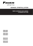
The illustration below shows the outlook and the dimensions of the unit (mm).
140
620
140
61
48
350
(345 ~ 355)
HOLE FOR ANCHOR
BOLT 4 M12
30
Outlook and
dimensions
320
11
1.2
ESIE08-01
30
41
96
3
30
3
900
4
3
2
1
7
6
7
5
6
5
55
89
24
89
19
142
19
52
80
145
8
71 16
10 60 102 117
1–4
67
5
43
Installation and
service space
13
58 16
45
55
223
6
84
95
54
435
95
5
5
54
60
410
7
148
1170
4
378
191
See page 1–26.
Part 1 – System Outline
ESIE08-01
1.3
General Outline: Altherma
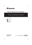
ERHQ011~016AAW1: Outlook and Dimensions
Outlook and
dimensions
1
The illustration below shows the outlook and the dimensions of the unit (mm)
HOLE FOR ANCHOR
BOLT 4 x M12
140
140
320
43
59
350
(345 ~ 355)
30
620
30
40
94
3
900
30
4
3
2
1
4
7
6
6
5
7
6
19
142
8
71
55
145
5
13
67
52
16
102
117
58
16
45
80
223
95
84 55
430
19
54
89
24
54
95
60
423
5
89
5
148
1345
7
10
60
5
43
Installation and
service space
Part 1 – System Outline
378
191
See page 1–26.
1–5
General Outline: Altherma
11
Components
3
ESIE08-01
The table below contains the different components of the unit.
No.
Component
1
Gas pipe connection φ15.9 flare
2
Liquid pipe connection φ9.5 flare
3
Service port (in the unit)
4
Electronic and Grounding terminal M5 (in switch box)
5
Refrigerant piping intake
6
Power supply wiring intake (knock out hole φ34)
7
Control wiring intake (knock out hole φ27)
8
Drain outlet
4
5
1–6
Part 1 – System Outline
ESIE08-01
1.4
General Outline: Altherma
EKHBH016A***: Outlook and Dimensions
Outlook and
dimensions
1
The illustration below shows the outlook and the dimensions of the unit (mm).
FIXATION
173
173
18
11
5
39
48
96
15
15
57
18
668
916
922
30
3
502
VIEW A
SCALE 1/5
66
35
15
35
60
15
361
89
4
13
4
12
3
53
297
107
107
469
14
DIMENSIONS WALL BRACKET
10
14
163
5
10
R6
R6
6
8
1
936
922
7a
916
895
7
16
7b
17
2
10
service door
138
(CLOSED) 361
(OPEN) 553
14
Installation and
service space
Part 1 – System Outline
MALE BSP
See page 1–28.
1–7
General Outline: Altherma
11
Components
3
4
5
1–8
ESIE08-01
The table below contains the different components of the unit.
No.
Component
1
Pump + switch for speed setting
2
Remocon
3
Water IN connection 1-1/4” M BSP
4
Water OUT connection 1-1/4” M BSP
5
Power supply intake (+ domestic hot water tank)
6
Air purge
7
Expansion vessel + 7a nipple + 7b drain
8
Blow off valve
9
Blow off drain (flexible hose φ20)
10
Pressure gauge
11
Waterfilter
12
Suction pipe connection φ15.9 flare connection
13
Liquid pipe connection φ9.52 flare connection
14
Shut off valves with drain/fill valve (accessory delivered with unit)
15
Holes for fixation
16
Switchbox terminals
17
Switchbox terminals option domestic hot water tank
18
Wallbracket
Part 1 – System Outline
ESIE08-01
1.5
General Outline: Altherma
EKHBX016A***: Outlook and Dimensions
Outlook and
dimensions
1
The illustration below shows the outlook and the dimensions of the unit (mm).
FIXATION
89
VIEW A
SCALE 1/5
173
173
18
916
3
668
922
15
15
15
107
30
57
18
10
502
107
14
DIMENSIONS WALL BRACKET
Scale 1/5
10
8
53
297
39
163
12
3
4
96
15
361
5
48
35
13
4
66
35
60
11
469
163
10
14
R6
R6
DIMENSIONS WALL BRACKET
10
163
10
R6
R6
6
8
1
936
922
7a
916
895
7
16
7b
17
2
10
service door
138
(CLOSED) 361
(OPEN) 553
14
Installation and
service space
Part 1 – System Outline
MALE BSP
See page 1–28.
1–9
5
General Outline: Altherma
11
Components
3
4
5
1–10
ESIE08-01
The table below contains the different components of the unit.
No.
Component
1
Pump + switch for speed setting
2
Remocon
3
Water IN connection 1-1/4” M BSP
4
Water OUT connection 1-1/4” M BSP
5
Power supply intake (+ domestic hot water tank)
6
Air purge
7
Expansion vessel + 7a nipple + 7b drain
8
Blow off valve
9
Blow off drain (flexible hose φ20)
10
Pressure gauge
11
Waterfilter
12
Suction pipe connection φ15.9 flare connection
13
Liquid pipe connection φ9.52 flare connection
14
Shut off valves with drain/fill valve (accessory delivered with unit)
15
Holes for fixation
16
Switchbox terminals
17
Switchbox terminals option domestic hot water tank
18
Wallbracket
Part 1 – System Outline
ESIE08-01
1.6
General Outline: Altherma
EKSWW150~300V3/Z2: Outlook and Dimensions - Service Space
Outlook and
dimensions Service space
1
The illustration below shows the outlook and the dimensions of the unit (mm).
47°
30°
23°
90°
0
40
0
40
0
40
30°
23°
300 L
47°
200 L
47°
150 L
3
30°
23°
90°
90°
300
8
2
4
300
8
9
2
6
2
9
9
7
6
3
3
6
1600
300
8
7
7
4
4
1150
900
3
5
4
1
1
110
580
0-40
110
220
580
0-40
0-40
110
220
1
580
5
630
630
5
220
475
5
Required service space
around the tank
Part 1 – System Outline
1–11
General Outline: Altherma
11
Components
3
ESIE08-01
The table below contains the different components of the unit.
No.
Component
1
Water mains IN female 3/4’ BSP
2
Water mains OUT female 3/4’ BSP
3
Thermistor connection female 1/2’ BSP
4
Flow (from Hydro-box) female 3/4’ BSP
5
Return (to Hydro-box) female 3/4’ BSP
6
Switchbox
7
Clixon
8
Connection female 1/2’ BSP
9
Power entrance
4
5
1–12
Part 1 – System Outline
ESIE08-01
1.7
General Outline: Altherma
EKHWS150~300*V3/Z2: Outlook and Dimensions - Service Space
Outlook and
dimensions Service space
1
The illustration below shows the outlook and the dimensions of the unit (mm)
3
4
5
3 WAY VALVE
Rp 1
REQUIRED SERVICE SPACE AROUND THE TANK
Part 1 – System Outline
1–13
General Outline: Altherma
11
Components
3
4
ESIE08-01
The table below contains the different components of the unit.
No.
Component
1
Water mains IN G 3/4’ BSP (female)
2
Water mains OUT G 3/4’ BSP (female)
3
Thermistor connection
4
Flow (from EKHB(H/X)*) G 3/4’ BSP (female)
5
Return (to EKHB(H/X)*) G 3/4’ BSP (female)
6
Switchbox
7
Thermal protector
8
Anode
9
Cable entry: Power supply booster heater and thermal protection cable
10
Re-circulation connection G 3/4’ BSP (female)
11
Cable entry for EKSOLHWAV1: Power supply from EKHB(H/X)
12
Cable entry for EKSOLHWAV1: Power supply to EKSOLHWAV1 pump
13
Thermistor connection (see EKSOLHWAV1)
14
3 way valve
5
1–14
Part 1 – System Outline
ESIE08-01
1.8
General Outline: Altherma
EKHWE150~300V3/Z2: Outlook and Dimensions - Service Space
The illustration below shows the outlook and the dimensions of the unit (mm)
27
300
Outlook and
dimensions Service space
1
851
410
1525
30
30
100
350
400
115
3
35
300
20~40
210
300L
13
2
30
100
30
350
10
1525
4
6
3
4
410
925
9
11
115
400
200L
20~40 280
5
1
5
30
100
255
775
1150
30
35
300
350
20~40
115
280
400
150L
30
12
775
115
280
220
255
705
1150
440
500
35
300
30
150L WALL-MOUNTED
REQUIRED SERVICE SPACE AROUND THE TANK
INSIDE OF SWITCHBOX
3-WAY VALVE
7
14
21
102
16
WALL PLATE 150L WALL-MOUNTED TANK
12
175
152
13
8
6
355
3x Rp 1
440
88
44
Scale 1:5
Scale 1:5
Part 1 – System Outline
1–15
General Outline: Altherma
11
Components
3
4
ESIE08-01
The table below contains the different components of the unit.
No.
Component
1
Cold water inlet: G 3/4 (male)
2
Hot water outlet: G 3/4 (male)
3
Thermistor hole
4
Flow (from EKHB(H/X)*): Rp 3/4 (female)
5
Return (to EKHB(H/X)*): Rp 3/4 (female)
6
Switchbox
7
Thermal protector
8
Anode
9
Cable entry
10
Re-circulation connection: G 3/4 (male)
11
Thermistor hole (see EKSOLHWAV1)
12
Wall plate 150L wall-mounted tank
13
Safety valve connection: G 1/2 (male)
14
3-way valve: 3x Rp 1 (female)
5
1–16
Part 1 – System Outline
ESIE08-01
1.9
General Outline: Altherma
EKSWWU150~300V3: Outlook and Dimensions - Service Space
The illustration below shows the outlook and the dimensions of the unit (mm).
40
0
Outlook and
dimensions Service space
1
MODEL
H1
H2
EKSWWU150V3
900
1015
EKSWWU200V3
1150
1265
EKSWWU300V3
1600
1715
3
4
1
7
2
23
300
5
5
9
8
10
≤500 mm
21
≤5
20
00
22
15
m
m
11
H2
19
12
H1
24
13
3
>300 mm
18
17
6
14
16
110
220
475
4
TYPICAL INSTALLATION
EKUSWW-KIT
580
REQUIRED SERVICE SPACE
Part 1 – System Outline
1–17
General Outline: Altherma
11
Components
3
4
5
1–18
ESIE08-01
The table below contains the different components of the unit.
No.
Water connections
Connection type
1
Water in (cold)
22 mm
2
Water out (hot)
3/4” female BSP
3
Flow from hydro-box
3/4” female BSP
4
Return to hydro-box
3/4” female BSP
5
Temperature relief valve
1/2” female BSP
6
Thermistor connection
No.
Water connections kit
Connection type
7
Pressure reducing valve
22 mm - 22 mm
8
T-piece (expansion valve)
22 mm - 1/2” female BSP - 22 mm
9
Expansion relief valve
1/2” male BSP - 1/2” female BSP
10
Adapter (relief valve)
1/2” male BSP - 15 mm
11
T-piece (to tundish)
15 mm - 15 mm - 1/2” female BSP
12
Tundish
22 mm - 15 mm
13
T-piece (to expansion vessel)
22 mm - 22 mm - 22 mm
14
Adapter (expansion vessel)
22 mm - 3/4” female BSP
15
Expansion vessel
3/4” male BSP
16
Drain valve
22 mm - 3/4” male BSP
17
Solenoid valve
3/4” female BSP - 3/4” female BSP
No.
Other components
18
Switch box
19
Thermal protector 1
20
Cable entrance power, booster heater, thermal protector
21
Power entrance solenoid valve
22
Control cable solenoid valve
23
Blind stop + 2 plastic screw-on closing caps for pressure reducing valve
24
Thermal protector 2 + thermostat
Part 1 – System Outline
ESIE08-01
1.10
General Outline: Altherma
EKHWSU150~300V3: Outlook and Dimensions - Service Space
Outlook and
dimensions Service space
1
The illustration below shows the outlook and the dimensions of the unit (mm)
MODEL
H1
H2
H3
H4
3
4
Rp 1
5
500 mm
500
300 mm
mm
TYPICAL INSTALLATION
EKUHWB-KIT
REQUIRED SERVICE SPACE
Part 1 – System Outline
1–19
General Outline: Altherma
11
Components
3
4
5
1–20
ESIE08-01
The table below contains the different components of the unit.
No.
Water connections
Connection type
1
Water in (cold)
22 mm
2
Water out (hot)
G 3/4 (female)
3
Flow from EKHB(H/X)*
G 3/4 (female
4
Return to EKHB(H/X)*
G 3/4 (female
5
Temperature relief valve
15 mm
6
Thermistor connection
-
7
Thermistor connection (see EKSOLHWAV1)
G 1/2 (female)
8
Re-circulation hole
G 3/4 (female)
No.
Water connections kit
Connection type
9
Pressure reducing valve
22 mm - 22 mm
10
Expansion relief valve
15 mm - 15 mm
11
T-piece (to tundish)
15 mm - 15 mm G 1/2 (female)
12
Tundish
22 mm - 15 mm
13
T-piece (to expansion vessel)
22 mm - 22 mm - 22 mm
14
Adapter (expansion vessel)
22 mm - G 3/4 (female)
15
Expansion vessel
G 3/4 (male)
16
Drain valve
22 mm - G 3/4 (female)
17
Reducing coupler
22 mm - 15 mm
No.
Other components
18
EKUHW2WB Kit: Solenoid valve (only with EKSOLHWAV1) Rp 3/4 - Rp 3/4
19
Switchbox
20
Thermal protector 1 + thermostat
21
Cable entry: power supply booster heater and thermal protector cable
22
Cable entry for EKUHW2WB: Power supply to solenoid valve
23
Cable entry for EKSOLHWAV1 & EKUHW2WB: Power supply from EKHB(H/X)
24
Blind stop + 2 plastic screw-on closing caps for pressure reducing valve
25
Thermal protector 2 + Thermostat
26
Cable entry for EKSOLHWAV1: power supply to EKSOLHWAV1 pump
27
3 way valve 3x Rp1
Part 1 – System Outline
8
6
19
16
14
5
7
3
278
460
0-40
153
DETAIL 1
10
4
16
1
4
16
2
16
153
89
EKSOLHWAV1 + EKHWS150*
9b
798
871
13
11
12
8
6
19
112
16
14
15
400
0-40
153
101
10
4
16
1
4
16
2
16
DETAIL 1
Scale: 1/20
SERVICE SPACE
Minimum SPACE for service & VENTILATION
5
7
3
EKSOLHWAV1 + EKHWS200-300*
871
824
590
220
590
220
278
460
Part 1 – System Outline
153
DETAIL 1
Scale: 1/4
9a
798
824
16
798
824
13
11
12
Outlook and
dimensions Service space
410
1.11
290
971
ESIE08-01
General Outline: Altherma
EKSOLHWAV1~EKHWS*: Outlook and Dimensions - Service Space
1
The illustration below shows the outlook and the dimensions of the unit (mm)
3
4
5
1–21
255
101
590
220
8
6
42
112
15
16
14
5
7
3
278
460
DETAIL 2
Scale: 1/4
0-40
823
849
871
153
10
4
14
1
4
14
2
14
DETAIL 2
153
17
101
9b
25
823
849
13
11
12
8
6
19
112
14
17
16
5
7
3
798
824
0-40
H1
101
MODEL
EKHWSU150*
EKHWSU200*
EKHWSU300*
Minimum SPACE for service & VENTILATION
16
DETAIL 1
Scale: 1/4
EKSOLHWAV1 + EKHWSU200-300*
871
1–22
278
5
590
220
4
290
971
153
Scale:1/20
SERVICE SPACE
H1
430
400
400
10
4
14
1
4
14
2
14
DETAIL 1
9a
3
460
798
824
11
12
13
Outlook and
dimensions Service space
153
1.12
410
255
11
EKSOLHWAV1 + EKHWSU150*
General Outline: Altherma
ESIE08-01
EKSOLHWAV1~EKHWSU*: Outlook and Dimensions - Service Space
The illustration below shows the outlook and the dimensions of the unit (mm)
Part 1 – System Outline
ESIE08-01
Components
General Outline: Altherma
1
The table below contains the different components of the unit.
No.
Components
1
Pump + switch for speed setting
2
Heat exchanger
3
EPP casing
4
Non return valves
No.
Connections
Connection type
5
Inlet connection from solar pump station
3/4” F BSP
6
Return connection to solar pump station
3/4” F BSP
7
Inlet connection from Altherma indoor unit
3/4” F BSP
8
Return connection to Altherma indoor unit
3/4” F BSP
9
EKSOLHWAV1 return connection to the
domestic hot water tank heat exchanger
3/4” F BSP
9a
200-300l tank
9b
150l tank
10
EKSOLHWAV1 inlet connection from the
domestic hot water tank heat exchanger
No.
Switchbox domestic hot water tank
11
Cable entry (Altherma indoor unit)
12
Cable entry (Pump cable)
No.
Accessories (delivered with
EKSOLHWAV1)
3
4
3/4” F BSP
5
Connection type
13
Thermistor socket (thermistor solar pump station) (internal diameter 6.1 mm)
-
14
Adapter
3/4” M BSP - 3/4” M BSP
For EKSOLHWAV1~EKHWS*
No.
Other accessories (delivered with
EKSOLHWAV1)
Connection type
15
Adapter
3/4” F BSP - 3/4” M BSP
16
Adapter
3/4” M BSP - 3/4” M BSP
For EKSOLHWAV1~EKHWSU*
Part 1 – System Outline
No.
Field supply
Connection type
15
Adapter (field supply)
3/4” M BSP - 3/4” M BSP
1–23
General Outline: Altherma
11
ESIE08-01
No.
EKUHWA-kit
Connection type
16
Solenoid valve
3/4” F BSP - 3/4” F BSP
17
Adapters (solenoid valve)
3/4” M BSP - 3/4” M BSP
3
4
5
1–24
Part 1 – System Outline
ESIE08-01
1.13
General Outline: Altherma
EKRTR / EKRTW: Outlook and Dimensions
Outlook and
dimensions
1
The illustrations below shows the outlook and the dimensions of the units (mm).
EKRTW
3
4
EKRTR
5
Part 1 – System Outline
1–25
General Outline: Altherma
11
1.14
ESIE08-01
ERHQ011~016AAV3*/W1*: Installation and Service Space
Installing near a
wall or obstacle
Where a wall or other obstacle is in the path of the outdoor unit air intake or exhaust airflow, follow the
installation guidelines below (stacked, multiple row).
Not stacked
The illustrations and table below show the required installation and service space (mm).
B2
3
D2
E
C
4
L1
H B1
A
L2
1
D1
B2
5
D2
E
C
L1
1
H B1
A
L2
D1
2
Suction side obstacle
1
In these cases, close the bottom
of the installation frame to
prevent discharged air from being
bypassed
2
In these cases, only 2 units can
be installed
Discharge side obstacle
Left side obstacle
Right side obstacle
This situation is not allowed
Top side obstacle
Obstacle is present
1–26
Part 1 – System Outline
ESIE08-01
Stacked
General Outline: Altherma
1
The illustration below shows the required installation and service space (mm).
■
Do not stack more than one unit.
■
+/- 100 mm is required as the dimension for laying the upper outdoor unit’s drain pipe.
■
Get the portion A sealed so that air from the outlet does not bypass.
1
Obstacles exist in front of the outlet side.
2
Obstacles exist in front of the air inlet.
A
≥ 100
≥ 100
≥ 1000
Multiple row
3
A
≥ 300
4
The illustration below shows the required installation and service space (mm).
1
Installing one unit per row.
2
Installing multiple units (2 units or more) in
lateral connection per row.
5
L
A
≥ 100
≥ 2000
≥ 200
≥ 1000
≥ 3000
H
≥ 600
≥ 1500
Relation of dimensions of H, A and L are shown in the table below.
L ≤H
H<L
Part 1 – System Outline
L
A
0 < L ≤1/2H
250
1/2H < L
300
Installation impossible
1–27
General Outline: Altherma
11
1.15
ESIE08-01
EKHBH(X)0016AA***: Installation and Service Space
EKHBH(X)
The illustration below shows the minimum service space for service and ventilation.
200
MINIMUM SPACE FOR SERVICE & VENTILATION
307
3
500
350
1150
132
449
300
Center of gravity
4
5
1–28
Part 1 – System Outline
ESIE08-01
1.16
General Outline: Altherma
Physical Limitations and Limits of Operation
Distance between
components
1
The illustrations and table below show the limitations.
OUTDOOR
F & F'
Domestic
hot tank
E
A
G & G'
I
INDOOR
C
Thermostat
H
J
B
3 way
valve 3
2 way valve
D
Heat
emitters
4
Allowable height:
Indoor
Total system : ≤ 30 m
(outdoor unit can be above
or below the Indoor)
outdoor
Piping
R410A
A
Piping water
B
C
≤3 m
≤ 10 m
Power supply
D
E
F & F’
Communication
G
G’
H
12 m
depend on
installation
> 0.05 m
I
J
ERHQ011AAV3(8)
ERHQ014AAV3(8)
5* < A ≤
75 m
ERHQ016AAV3(8)
ERHQ011AAW1(8)
ERHQ014AAW1(8)
depend on depend on depend on
installation installation installation
depend on depend on
installation installation
3 < A ≤ 75
m
ERHQ016AAW1(8)
Part 1 – System Outline
1–29
5
General Outline: Altherma
11
Remark
■
ESIE08-01
A: Minimum allowed length is 3 m. Refer to the installation manual of the outdoor unit.
■
V3(8) ONLY:
When < 5 m, recharging of the outdoor unit is required.
It is not necessary to charge additionally if the piping length is under 30 m
■
W1(8) ONLY:
It is not necessary to charge additionally if the piping length is under 10 m
3
■
E: 123-wiring in/outdoor
■
F: Power supply booster + Q2L safety
■
F': Power supply solenoid valve (UK only)
■
G: Thermistor cable supplied with the domestic hot water tank is 12 m in length. May not be
changed.
■
G': Feedback signal Q2L & Q3L safety (UK only)
4
5
1–30
Part 1 – System Outline
ESIE08-01
1.17
General Outline: Altherma
EKHBDP - Drainpan Kit Necessity
Decision graph for
EKHBDP necessity
1
Leaving water temperature limit to prevent condensation
31
31.0
Relative humidity 40%
Relative humidity 60%
Relative humidity 80%
28
28.0
Maximum leaving
water temperature cooling mode = 22 C.
3
25
22.0
22
19.0
19
16.0
16
Leaving water temperature ( C)
Leaving water temperature ( C)
25.0
13
13.0
12.0
Example :
With ambient temperature of 25 C and
relative humidity of 40%.
If leaving water temperature is below
12 C, condensation on water piping will happen.
10.0
10
7
7.0
20
23
25
26
29
32
Dry bulb temperature ( C)
Remark
Part 1 – System Outline
1
Refer to psychometric chart for more information.
2
If condensation is expected, installation of EKHBDP - drainpan kit must be considered.
1–31
4
5
General Outline: Altherma
ESIE08-01
11
3
4
5
1–32
Part 1 – System Outline
ESIE08-01
Specifications
Part 1
1
2
Specifications
2.1
What Is in This Chapter?
Introduction
Altherma
Part 1 – System Outline
This chapter contains the following information:
■
Technical specifications
■
Electrical specifications
3
This chapter contains the following specifications:
Topic
See page
2.2–Technical and Electrical Specifications for ERHQ011~016AAV3
1–34
2.3–Technical and Electrical Specifications for ERHQ011~016AAW1
1–37
2.4–Technical and Electrical Specifications for EKHBH016AA*** & EKHBX016AA***
and EKHBH016AB*** & EKHBX016AB***
1–40
2.5–Technical and Electrical Specifications for EKSWW150~300V3/Z2 &
EKHWS150~300*V3/Z2
1–43
2.6–Technical and Electrical Specifications for EKSWWU150~300V3 &
EKHWSU150~300*V3
1–44
2.7–Technical and Electrical Specifications for EKSOLHWAV1
1–45
2.8–Technical and Electrical Specifications for EKRTW / EKRTR
1–46
4
5
1–33
Specifications
11
2.2
ESIE08-01
Technical and Electrical Specifications for ERHQ011~016AAV3
Technical
specifications
The table below contains the technical specifications.
Specification
EKHBH*
hydro-boxes
EKHBX*
ERHQ011AA*
ERHQ014AA*
ERHQ016AA*
ERHQ011AA*
ERHQ014AA*
ERHQ016AA*
EKHBH016A**
EKHBH016A**
EKHBH016A**
EKHBX016A**
EKHBX016A**
EKHBX016A**
Colour
Ivory white
Casing
Material
Packing
3
Painted galvanised steel plate
Height
1349 mm
Width
980 mm
Depth
420 mm
Height
1170 mm
Dimensions
Unit
Width
900 mm
Depth
320 mm
Machine weight
103 kg
Weight
Gross weight
Packing
4
114 kg
Material
EPS, Carton, Wood, PE (straps)
Weight
Heat exchanger
Specifications
11 kg
Length
857 mm
Nr. of rows
2
Fin pitch
1.4 mm
Nr. of passes
6
Face area
0.98 m²
Nr. of stages
52
Empty tubeplate hole
5
0
Tube type
Fin
Hi-XSS(8)
Type
WF fin
Treatment
Fan
Anti-corrosion treatment (PE)
Type
Propeller
Quantity
2
Air flow rate (nominal Heating high
at 230 V)
Cooling low
—
—
—
96 m³/min
100 m³/min
97 m³/min
90 m³/min
90 m³/min
90 m³/min
90 m³/min
90 m³/min
90 m³/min
Discharge direction
Horizontal
External statis pressure (Max)
Motor
—
Quantity
2
Model
Position
—
Speed (nominal at 230 V)
- number of steps
8
Speed (nominal at 230 V)
- cooling
—
—
—
800 rpm
850 rpm
830 rpm
Speed (nominal at 230 V)
- heating
760 rpm
760 rpm
760 rpm
760 rpm
760 rpm
760 rpm
Output
Compressor
Direct drive
Model
JT100G-VD
Type
Hermetically sealed scroll compressor
1
Speed
Motor output
Starting method
Crankcase heater
1–34
70 W
Drive
Quantity
Motor
Brushless DC motor
—
2200 W
Inverter driven
33 W
Part 1 – System Outline
ESIE08-01
Specifications
Specification
EKHBH*
hydro-boxes
Operation range
Heating
EKHBX*
ERHQ011AA*
ERHQ014AA*
ERHQ016AA*
ERHQ011AA*
ERHQ014AA*
ERHQ016AA*
EKHBH016A**
EKHBH016A**
EKHBH016A**
EKHBX016A**
EKHBX016A**
EKHBX016A**
Min.
-20°C DB
Max.
Cooling
35°C DB
Min.
—
Max.
—
Domestic hot water
Min.
Heating
Sound power
10 °C DB
46 °C DB
-20°C DB
Max.
Sound level (nominal)
43°C DB
Sound pressure (1)
Cooling
Sound power
Sound pressure
Sound level (night quiet)
Refrigerant
(1)
—
—
—
64 dBA
64 dBA
66 dBA
49 dBA
51 dBA
53 dBA
49 dBA
51 dBA
53 dBA
—
—
—
64 dBA
66 dBA
69 dBA
—
—
—
50 dBA
52 dBA
54 dBA
Heating
Sound pressure
42 dBA
42 dBA
43 dBA
42 dBA
42 dBA
43 dBA
Cooling
Sound pressure
—
—
—
45 dBA
45 dBA
46 dBA
Type
3.7 kg
Control
Expansion valve (electronic type)
Nr. of circuits
Type
Piping connections
Liquid
1
Daphne FVC68D
Charged volume
Diameter (OD)
Gas
Quantity
Type
Diameter (OD)
Drain
Quantity
Type
Diameter (OD)
Piping length
1
Flare connection
9.52 mm
1
Flare connection
15.9 mm
26 mm
5m
Max.
75 m
Equivalent
95 m
Additional refrigerant charge
Installation height difference max.
30 m
See installation manual outdoor unit 4PW37976-1 B
30 m
Both liquid and gas pipes
Defrost method
Pressure equalising
Defrost control
Sensor for outdoor heat exchanger temperature
Capacity control method
5
3
Hole
Min. (2)
Chargeless
Heat insulation
4
1.0 l
Quantity
Type
Inverter controlled
Capacity control (%)
—
Safety devices
High pressure switch
Fan motor thermal protector
Fuse
Standard accessories
Item
Standard accessories
Item
Tie wraps
Quantity
1
(1)
The sound pressure level is measured via a microphone at a certain distance from the unit. It is a relative value depending on
the distance and acoustic environment. Refer to sound spectrum drawing for more information.
(2)
Part 1 – System Outline
2
Installation manual
Quantity
Notes
3
R410A
Charge
Refrigerant oil
1
Down to 3 m with recharging of the outdoor unit. Refer to the installation manual of the outdoor unit.
1–35
Specifications
11
Electrical
specifications
ESIE08-01
The table below contains the electrical specifications.
Specification
EKHBH*
hydro-boxes
Power supply
EKHBX*
ERHQ011AA*
ERHQ014AA*
ERHQ016AA*
ERHQ011AA*
ERHQ014AA*
ERHQ016AA*
EKHBH016A**
EKHBH016A**
EKHBH016A**
EKHBX016A**
EKHBX016A**
EKHBX016A**
Name
V3
Phase
1~
Frequency
50 Hz
Voltage
Current
Nominal running current
230 V
Cooling
—
Heating
—
Starting current
Zmax
3
—
List
Text
Maximum running current
Voltage range
Wire connections
—
—
—
22.8 A
27.4 A
31.9 A
Heating
—
—
—
—
—
—
Recommended fuses
32 A
Minimum
207 V
For power supply
253 V
Quantity
Remark
For connection with hydro-box
See installation manual outdoor unit 4PW37976-1 B
Quantity
Remark
Power supply intake
—
Cooling
Maximum
4
no requirements
See installation manual outdoor unit 4PW37976-1 B
Outdoor unit only
5
1–36
Part 1 – System Outline
ESIE08-01
2.3
Specifications
Technical and Electrical Specifications for ERHQ011~016AAW1
Technical
specifications
1
The table below contains the technical specifications.
Specification
Heating only type
Reversible type
ERHQ011AAW1 ERHQ014AAW1 ERHQ016AAW1 ERHQ011AAW1 ERHQ014AAW1 ERHQ016AAW1
indoor units
EKHBH016A**
EKHBH016A**
EKHBH016A**
Colour
EKHBX016A**
EKHBX016A**
EKHBX016A**
Ivory white
Casing
Material
Packing
Painted galvanised steel plate
Height
1524 mm
Width
980 mm
Depth
420 mm
Height
1345 mm
Width
900 mm
Depth
320 mm
Dimensions
Unit
Weight of unit
Weight of packing materials
Heat exchanger
Machine net weight (ERHQ*W1*/ERHQ*W18*)
108/110 kg
Packed machine weight
(ERHQ*W1*/ERHQ*W18*)
120/122 kg
Material
EPS, Carton, Wood, PE (straps)
Weight
Specifications
857 mm
2
Fin pitch
1.4 mm
Nr. of passes
5
Face area
1.131 m²
Nr. of stages
60
Empty tubeplate hole
Hi-XSS(8)
Type
WF fin
Treatment
Anti-corrosion treatment (PE)
Type
Propeller
Quantity
2
Air flow rate (nominal Cooling
at 230 V)
Heating
-
-
-
-
-
-
-
-
-
-
-
-
Discharge direction
Horizontal
External static pressure (Max)
-
Motor
2
Quantity
Model
-
Speed (nominal at 230 V)
- number of steps
8
Speed (nominal at 230 V)
- cooling
—
—
—
780 rpm
780 rpm
780 rpm
Speed (nominal at 230 V)
- heating
760 rpm
760 rpm
760 rpm
760 rpm
760 rpm
760 rpm
Direct drive
Model
JT1G-VDYR@T
Type
Hermetically sealed scroll compressor
1
Speed
Motor output
Starting method
Crankcase heater
Part 1 – System Outline
70 W
Drive
Quantity
Motor
Brushless DC motor
Position
Output
Compressor
5
0
Tube type
Fin
4
12 kg
Length
Nr. of rows
Fan
3
2200 W
Inverter driven
33 W
1–37
Specifications
11
ESIE08-01
Specification
Heating only type
Reversible type
ERHQ011AAW1 ERHQ014AAW1 ERHQ016AAW1 ERHQ011AAW1 ERHQ014AAW1 ERHQ016AAW1
indoor units
Operation range
EKHBH016A**
Heating
EKHBH016A**
EKHBH016A**
Min.
Max.
Cooling
Domestic hot water
Heating (3)
Cooling (4)
Sound level (night quiet)
Refrigerant
10 °C DB
Max.
—
46 °C DB
Min.
-20°C DB
64 dBA
64 dBA
66 dBA
64 dBA
64 dBA
Sound pressure (1)
51 dBA
51 dBA
52 dBA
51 dBA
51 dBA
66 dBA
52 dBA
Sound power
64 dBA
66 dBA
69 dBA
64 dBA
66 dBA
69 dBA
—
—
—
50 dBA
52 dBA
54 dBA
Heating
Sound pressure
42 dBA
42 dBA
43 dBA
42 dBA
42 dBA
43 dBA
Cooling
Sound pressure
—
—
—
45 dBA
45 dBA
46 dBA
Type
R410A
Charge
2.95 kg
Control
Expansion valve (electronic type)
Refrigerant oil
Type
Piping connections
Liquid
1
Daphne FVC68D
Charged volume
1.0 l
Quantity
Type
Diameter (OD)
Gas
Quantity
Type
Diameter (OD)
5
43°C DB
Sound power
Nr. of circuits
4
EKHBX016A**
35°C DB
—
Sound pressure (1)
3
EKHBX016A**
Min.
Max.
Sound level (nominal)
EKHBX016A**
-20°C DB
Drain
Quantity
Type
Diameter (OD)
Piping length
9.52 mm
1
Flare connection
15.9 mm
4
Hole
3x26 / 1x18
Min. (2)
5m
Max.
75 m
Equivalent
95 m
Chargeless
10 m
Additional refrigerant charge
Installation height difference max.
Max. interunit level difference
Heat insulation
1
Flare connection
See installation manual outdoor unit 4PW42025-1
30 m
Both liquid and gas pipes
Defrost method
Pressure equalising
Defrost control
Sensor for outdoor heat exchanger temperature
Capacity control method
Inverter controlled
Capacity control (%)
—
Safety devices
High pressure switch
Fan motor thermal protector
Fuse
Standard accessories
Item
Standard accessories
Item
Tie wraps
Quantity
Quantity
Notes
1
(1)
The sound pressure level is measured via a microphone at a certain distance from the unit. It is a relative value depending on
the distance and acoustic environment. Refer to sound spectrum drawing for more information.
(2)
1–38
2
Installation manual
Down to 3 m with recharging of the outdoor unit. Refer to the installation manual of the outdoor unit.
Part 1 – System Outline
ESIE08-01
Specifications
Electrical
specifications
Specification
Heating only type
indoor units
Power supply
Name
ERHQ016AAW1
ERHQ011AAW1
ERHQ014AAW1
ERHQ016AAW1
EKHBH016A**
EKHBH016A**
EKHBX016A**
EKHBX016A**
EKHBX016A**
400 V
Cooling
—
Heating
5.8 A
Starting current (cooling/heating)
—
Zmax
-
Minimum Ssc value
-
Maximum running current
(ERHQ*W1*/ERHQ*W18*)
Cooling
Heating
20 A
Minimum
360 V
For power supply
440 V
See installation manual outdoor unit 4PW42025-1
Quantity
Remark
Power supply intake
4
Quantity
Remark
For connection with hydro-box
3
13.5/14
Recommended fuses
Maximum
Wire connections
ERHQ014AAW1
EKHBH016A**
50 Hz
Voltage
Voltage range
ERHQ011AAW1
3N~
Frequency
Nominal running current
Reversible type
W1*
Phase
Current
1
The table below contains the electrical specifications.
See installation manual outdoor unit 4PW42025-1
Outdoor unit only
5
Part 1 – System Outline
1–39
Specifications
11
2.4
ESIE08-01
Technical and Electrical Specifications for EKHBH016AA*** & EKHBX016AA***
and EKHBH016AB*** & EKHBX016AB***
Technical
specifications
The table below contains the technical specifications.
Specification
Outdoor units
ERHQ011AA
EKHBH*
EKHBX*
EKHBH016AA*/AB*
EKHBH016AA*/AB*
ERHQ014AA
ERHQ016AA
Nominal input (indoor only without electric heater)
Casing
3
4
Epoxy polyester painted galvanised steel
Packing
Height
1225 mm
Width
660 mm
Depth
610 mm
Height (1)
922 mm
Width
502 mm
Depth
361 mm
Machine net weigth
55 kg
Packed machine weight
Packing
Material
Main components
Pump
65 kg
EPS, Wood, Carton, PP (straps)
Weight
10 kg
Type
Water cooled
Nr. of speed
5
2
Nominal ESP unit Cooling
—
—
—
55.9 kPa
49.1 kPa
46.8 kPa
Nominal ESP unit Heating
52.5 kPa
43.5 kPa
35.0 kPa
52.5 kPa
43.5 kPa
35.0 kPa
Power input
Water side Heat
exchanger
210 W
Type
Brazed plate
Quantity
1
Water volume
1.01 l
Water flow rate Min.
16 l/min
Water flow rate Nom. Cooling (2)
Water flow rate Nom. Heating
Sound level
28.7 l/min
35.8 l/min
37.6 l/min
32.1 l/min
40.1 l/min
45.9 l/min
32.1 l/min
40.1 l/min
45.9 l/min
58 l/min
Volume
Polyurethane foam
10 l
3 bar
Pre-pressure
1 bar
Diameter perforations
1 mm
Piping connections diameter
Brass
1-1/4” MBSP
Piping
1”-1/4
Safety valve
3 bar
Manometer
Yes
Drain valve / Fill valve
Yes
Shut off valve
Yes
Air purge valve
Yes
Total water volume (6)
5.5 l
Gas side diameter
15.9 mm
Liquid side diameter
9.52 mm
Sound pressure
Sound power
1–40
—
58 l/min
Material
Refrigerant ciruit
—
Water flow rate Max. Heating
Max. water pressure
Water filter
(3)
—
Water flow rate Max. Cooling
Insulation material
Expansion vessel
Water circuit
ERHQ016AA
RAL9010
Unit
Weight of unit
ERHQ014AA
230 W
Colour
Material
Dimensions
ERHQ011AA
(4)
28 dBA
—
Part 1 – System Outline
ESIE08-01
Specifications
Specification
Outdoor units
Operation range
(ERHQ0** /
AAV3*)
ERHQ011AA
EKHBH*
EKHBX*
EKHBH016AA*/AB*
EKHBH016AA*/AB*
ERHQ014AA
ERHQ011AA
ERHQ014AA
Cooling
—
10~46°C
Heating
-20~35°C
-20~35°C
Waterside
Cooling
—
5~22°C
15~55°C
15~55°C
Heating(5)
Operation range
(ERHQ0** /
AAW1*)
ERHQ016AA
Ambient
Ambient
Cooling
Heating(7)
Waterside
—
10~46°C
-25~35°C
-25~35°C
Cooling
Heating(5)
Notes
(1)
With option kit EKHBDP installed: Height = 936 mm
(2)
Tamb 35°C - LWE 7°C (DT = 5°C)
(3)
DB/WB 7°C/6°C - LWC 35°C (DT = 5°C)
—
5~22°C
15~55°C
15~55°C
1
ERHQ016AA
3
(4) The sound pressure level is measured via a microphone at 1 m from the unit. It is
a relative value depending on the distance and
acoustic environment. The sound pressure level mentioned is valid for pump medium speed.
Electrical
specifications
Electric heater
(optional)
(5)
15°C~25°C: BUH only, no Heatpump operation = during commissioning
(6)
Including piping + PHE + backup heater / excluding expansion vessel
(7)
-25 ~ -20°C: operation of heat pump possible, but no guarantee of capacity (if outdoor temperature < -25°C unit will stop)
The table below contains the electrical specifications.
Type
Power supply (1) (2)
3V3
6V3
6WN
6T1
9WN
9T1
1~
1~
3~
3~
3~
3~
Voltage
230 V
230 V
400 V
230 V
400 V
230 V
Running current
13 A
26 A
8.7 A
15.1 A
13 A
22.6 A
Out of scope
Phase
Frequency
Current
Zmax
Wiring
connections
50 Hz
List
No requirements
—
No requirements
Out of scope
No requirements
Text
—
0.25 + j0.15
—
—
—
—
List
—
—
No requirements
Out of scope
No requirements
Out of scope
Text
0.25 + j0.15
0.15 + j0.09
—
—
—
—
Minimum
207 V
207 V
360 V
207 V
360 V
207 V
Maximum
253 V
253 V
440 V
253 V
440 V
253 V
3G
3G
4G
4G
4G
4G
Note (3)
Note (3)
Note (3)
Note (3)
Note (3)
Note (3)
Zmax (electric
heater) + booster
heater (EKSWW*
models)
Voltage range
4
For power supply
backup heater
Quantity of wires
Type of wires
For power supply
connection to
optional DHW tank
+ Q2L
Quantity of wires
3G
Type of wires
(3)
For connection with
R5T
Quantity of wires
Note (7)
Type of wires
Note (7)
Quantity of wires
Note (6)
For connection with
A3P
Type of wires
For connection with
M2S
For connection with
M3S
Notes
and (4)
Note (3) and (5)
Quantity of wires
3G
Type of wires
(3)
Quantity of wires
Type of wires
Note
and (5)
3G or 4G
Note (3) and (5)
(1) Above mentioned power supply of the hydro-box is for the backup heater only.
The switch box & pump of the hydro-box are supplied via the outdoor unit.
The optional domestic warm water tank has a separate power supply.
(2)
Part 1 – System Outline
Note
Optional electric heater has 2 capacity steps except for the 3V3 model which has only one capacity step.
1–41
5
Specifications
11
ESIE08-01
(3)
Select diameter and type according to national and local regulations.
(4)
For more details of the voltage range and current refer to installation manual EKHBH/X016A**.
(5)
Voltage: 230 V / Maximum current: 100 mA / Minimum 0.75 mm².
(6)
Depends on thermostat type, refer to installation manual EKHBH/X016A**.
(7)
Wire included in option EKSWW*/EKHWS*/EKHWE*.
3
4
5
1–42
Part 1 – System Outline
ESIE08-01
2.5
Specifications
Technical and Electrical Specifications for EKSWW150~300V3/Z2 &
EKHWS150~300*V3/Z2
Technical
specifications
The table below contains the technical specifications.
EKSWW150V3
EKHWS150*V3
Specification
Casing
EKSWW200V3
EKHWS150*V3
Colour
Packing
Height
950 mm
1200 mm
1650 mm
Height
1200 mm
1650 mm
1150 mm
1600 mm
600 mm
900 mm
1150 mm
1600 mm
Width
580 mm
Depth
580 mm
Machine weight
37 kg
45 kg
59 kg
45 kg
59 kg
Gross weight (EKSWW)
40 kg
49 kg
64 kg
49 kg
64 kg
Gross weight (EKHWS)
42 kg
51 kg
66 kg
51 kg
66 kg
Packing
Material
Main components
Tank
Water volume
3 kg
4 kg
5 kg
4 kg
5 kg
150 l
200 l
300 l
200 l
300 l
Material
Max. temperature
85°C
10 bar
Insulation Material
Polyurethane foam
Insulation Min. thickness
Booster heater
40 mm
Quantity
5
1
Material (EKSWW)
Stainless steel (DIN 1.4401)
Material (EKHWS)
Duplex steel LDX 2101
Quantity
1
Capacity
3 kW
Temperature sensor
Cable length
Piping connections
Water inlet H/E Diameter
3/4” FBSP (inch)
Water outlet H/E Diameter
3/4” FBSP (inch)
Cold water in Diameter
3/4” FBSP (inch)
Hot water out Diameter
3/4” FBSP (inch)
Electrical
specifications
12 m
The table below contains the electrical specifications.
EKSWW150V3
EKHWS150*V3
Specification
Power supply
Phase
EKSWW200V3
EKHWS150*V3
Voltage
Fuse
EKSWW200Z2
EKHWS150*V3
EKSWW300Z2
EKHWS150*V3
2~
50 Hz
230 V
400 V
13 A
Size
Phase
Part 1 – System Outline
EKSWW300V3
EKHWS150*V3
1~
Frequency
Nominal running current
4
Stainless steel (DIN 1.4521)
Max. water pressure
Heat exchanger
3
EPS/Carton
Weight
Unit
EKSWW300Z2
EKHWS150*V3
600 mm
Depth
Weight
EKSWW200Z2
EKHWS150*V3
Epoxy-coated mild steel
Width
Unit
EKSWW300V3
EKHWS150*V3
Neutral white
Material
Dimensions
1
7.5 A
20 A
1~
2~
1–43
Specifications
11
2.6
ESIE08-01
Technical and Electrical Specifications for EKSWWU150~300V3 &
EKHWSU150~300*V3
Technical
specifications
The table below contains the technical specifications.
Specification
Casing
EKSWWU150V3
EKSWWU200V3
EKSWWU300V3
EKHWSU150*V3
EKHWSU150*V3
EKHWSU150*V3
Colour
Neutral white
Material
Dimensions
Packing
Epoxy-coated mild steel
Height
1040 mm
1280 mm
Width
Depth
Unit
Height
600 mm
1015 mm
1265 mm
Width
3
Packing
4
580 mm
Machine weight
38 kg
46 kg
60 kg
Gross weight (EKSWW)
41 kg
50 kg
65 kg
Gross weight (EKHWS)
43 kg
52 kg
67 kg
Material
EPS/Carton
Weight
Main components
Tank
Water volume
Material
3 kg
4 kg
5 kg
150 l
200 l
285 l
Stainless steel (DIN 1.4521)
Max. temperature
85°C
Max. water pressure
10 bar
Insulation Material
Polyurethane foam
Insulation Min. thickness
Heat exchanger
5
Booster heater
Electrical
specifications
40 mm
Quantity
1
Material (EKSWW)
Stainless steel (DIN 1.4401)
Material (EKHWS)
Duplex steel LDX 2101
Quantity
1
Capacity
3 kW
Temperature sensor
Cable length
Piping connections
Water inlet H/E Diameter
3/4” FBSP (inch)
12 m
Water outlet H/E Diameter
3/4” FBSP (inch)
Cold water in Diameter
3/4” FBSP (inch)
Hot water out Diameter
3/4” FBSP (inch)
The table below contains the electrical specifications.
Specification
Unit
Power supply
Phase
Fuse
EKSWWU150V3
EKSWWU200V3
EKSWWU300V3
EKHWSU150*V3
EKHWSU150*V3
EKHWSU150*V3
1~
Frequency
50 Hz
Voltage
230 V
Nominal running current
13 A
Size
Phase
1–44
1715 mm
580 mm
Depth
Weight
1735 mm
600 mm
20 A
1~
Part 1 – System Outline
ESIE08-01
2.7
Specifications
Technical and Electrical Specifications for EKSOLHWAV1
Technical
specifications
The table below contains the technical specifications.
Specification
Dimensions
EKSOLHWAV1
Packing
Unit
Weight of unit
Height
340 mm
Depth
295 mm
Height
770 mm
Width
305 mm
Depth
270 mm
Machine weight
Weight of packing materials
Material
Heat exchanger
Type
8 kg
9 kg
1 kg
Brazed plate
Pressure drop
Solar side
21.5 kPa
Maximum inlet temperature
Solar side
110 °C
Heat exchange capacity
1400 W/K
Logarithmic mean temperature difference (LMTD)
Type
3
Nominal ESP
Heating
Power input
Medium speed
46 W
Min.
-
Max.
-
Nom.
Sound
Sound pressure
Water circuit
Piping connection diameter
5
27 dBA
Insulation material
Ambient temperature
4
5K
water cooled
Number of speeds
Water flow rate
3
Carton
Weight
Pump
795 mm
Width
Gross weight
Electrical
specifications
1
3/4” F BSP
EPP
Max.
35 °C
Min.
1 °C
The table below contains the electrical specifications.
Specification
Unit
EKSOLHWAV1
Power supply
Phase
Frequency
Voltage
Nominal running current
Fuse
Wiring connections
1~
50 Hz
220-240 V
Not applicable
Size
Not applicable
Phase
Not applicable
For power supply
Quantity
Not applicable
Remark
Not applicable
For connection with
indoor
Quantity
Not applicable
Remark
Not applicable
Minimum
-10%
Maximum
+10%
Voltage range
Power supply intake
Part 1 – System Outline
indoor unit
1–45
Specifications
11
2.8
ESIE08-01
Technical and Electrical Specifications for EKRTW / EKRTR
Technical
specifications
The table below contains the technical specifications.
Specification
EKRTW
EKRTR
Thermostat
Dimensions
Packing
Unit
Weight of unit
3
Weight of packing
Ambient temperature
4
Receiver
Height (mm)
65
70
Width (mm)
175
200
75
Depth (mm)
100
140
75
45
Height (mm)
87
87
170
Width (mm)
125
125
50
-
Depth (mm)
34
34
28
-
210
Net weight
g
215
Gross weight
g
440
Material
g
55
Storage
°C
-20~60
125
665
Carton
Weight
Operation
EKRTETS
Carton
3 m wire length
65
80
Carton
Carton
-20~60
-20~60
-20~60
0~50
85
15
°C
0~50
0~50
0~50
Temperature setpoint range heating
°C
4-37
4-37
-
-
Temperature setpoint range cooling
°C
4-37
4-37
-
-
Temperature setting resolution
°C
Clock
Regulation function
0,5
0,5
-
-
Yes
Yes
-
-
Proportional
band
Proportional
band
-
-
Features:
5
Heating only
Yes
Yes
-
-
Heating and cooling
Yes
Yes
-
-
Comfort function mode (= comfort setpoint)
Yes
Yes
-
-
Reduced function mode (= night setback setpoint)
Yes
Yes
-
-
Scheduled function mode (= schedule timer)
Yes
Yes
-
-
12/day
12/day
-
-
Holiday function mode
Yes
Yes
-
-
Off function (with integrated frost protection)
Yes
Yes
-
-
Number of setpoint changes
Dew prevention
No
No
-
-
Setpoint limitation
Yes
Yes
-
-
Keylock function
Yes
Yes
-
-
No
Yes (only in combination with
EKRTETS)
-
-
Floor temperature protection
Additional
information
The table below contains additional information.
Comfort function mode
Use this mode for a fixed temperature on comfort level (comfort setpoint default on 21°C in heating mode, 24°C in
cooling mode).
Reduced function mode
Use this mode for a fixed temperature on reduced level (reduced setpoint default on 17°C in heating mode, 28°C in
cooling mode).
Use this mode to let your installation be controlled by the schedule timer. The actions programmed in the schedule
Scheduled function mode
timer will be executed automatically according to the actual time. This function uses the scheduled temperature setpoint.
Holiday function mode
Off function
Use this mode to set a fixed temperature during a long absence.
Use this mode to switch off your installation. Integrated frost protection remains activated (frost protection default on
4°C in heating mode).
1–46
Setpoint limitation
Use this function to limit the setpoint range for the end customer.
Floor temperature protection
Use this function to set a maximum and a minimum floor temperature.
Part 1 – System Outline
ESIE08-01
Electrical
specifications
Specifications
The table below contains the electrical specifications.
Specification
Power supply
EKRTW
Phase
Thermostat
Receiver
-
-
1~
-
Hz
-
-
50
-
Voltage
V
Battery powered
3x AA-LR6 (alkaline)
Battery powered
3x AA-LR6 (alkaline)
230
-
-
-
± 10%
-
Wired
Wireless
Wired
Wired
-
Voltage tolerance
Max rated switching current
EKRTETS
Frequency
Connection
Max distance to receiver
EKRTR
Indoor
-
Approx. 30 m
-
Outdoor
-
Approx. 100 m
-
-
5A
-
4A
-
A (at 230
VAC)
1
3
4
5
Part 1 – System Outline
1–47
Specifications
ESIE08-01
11
3
4
5
1–48
Part 1 – System Outline
ESIE08-01
Functional Diagrams
Part 1§
1
3
Functional Diagrams
3.1
What Is in This Chapter?
Introduction
Functional
diagrams
Part 1 – System Outline
This chapter contains the following information:
■
Overview complete system
■
Electrical connection diagram
■
Pipe connection diameters.
3
This chapter contains the following functional diagrams:
Topic
See page
3.2–Complete System (ERHQ011~016AAV3 + EKHBH/X016AA*** +
EKSWW)
1–50
3.3–Complete System (ERHQ011~016AAW1 + EKHBH/X016AB +
EKHWS(U)/EKHWE)
1–52
3.4–Electrical Connection Diagram
1–55
3.5–Pipe Connection Diameters
1–56
4
5
1–49
1–50
11
COOLING
HEATING
OR6T
1
OR4T
13
2
9
p >
7
3
8
6
10
2
5
4
14
IR4T
t >
15
19
EVAPORATOR
CONDENSOR
21
20
18
24
IR2T
t >
22
23
23
M
27
M
25
28
26
3
: COOLING (EKHBX)
: HEATING (EKHBX + EKHBH)
IR3T
t >
IR1T
t >
17
16
5
OR5T
12
M
OR2T
IR5T
t >
29
30
M
T1
M
T1
FCU1
11
3.2
OR3T
OR1T
Functional Diagrams
ESIE08-01
Complete System (ERHQ011~016AAV3 + EKHBH/X016AA*** +
EKSWW)
4
Part 1 – System Outline
p <
ESIE08-01
Components
Functional Diagrams
1
The table below contains the different components of the functional diagrams.
No.
Name
Outdoor Unit
1
Heat exchanger (Outdoor unit)
2
Filter (Outdoor, refrigerant)
3
Expansion valve
4
Liquid stop valve with service port
5
Gas stop valve with service port
6
Pressure sensor (Outdoor unit)
7
4-way valve ON: heating
8
High pressure switch discharge pipe (Outdoor unit)
9
Compressor
10
Accumulator
11
Service port 5/16”
12
Propeller fan
13
Crankcase heater compressor
OR1T
Outdoor air temperature thermistor
OR2T
Discharge pipe thermistor (Outdoor unit)
OR3T
Suction pipe thermistor (Outdoor unit)
OR4T
Heat exchanger thermistor (Outdoor unit)
OR5T
Heat exchanger middle thermistor (Outdoor unit)
OR6T
Liquid refrigerant thermistor (Outdoor unit)
3
4
5
Hydro-box
14
Heat exchanger PME (hydro-box)
15
Backup heater
16
Expansion vessel
17
Drain valve
18
Manometer
19
Air purge valve
20
Pressure relief valve
21
Pump
22
Flow switch
23
Shut off valve with drain/fill valve
24
Filter (hydro-box, water)
IR1T
Outlet water Heat exchanger thermistor (hydro-box)
IR2T
Outlet water Backup heater thermistor (hydro-box)
IR3T
Liquid refrigerant thermistor (hydro-box)
IR4T
Inlet water thermistor (hydro-box)
IR5T
Domestic hot water tank thermistor (hydro-box)
DHW
25
3-way valve for domestic hot water tank
26
DHW tank
27
2-way valve to block heating supply to tank heat exchanger (EKSWWU only)
28
Booster heater
Field supplied
Part 1 – System Outline
29
By-pass valve
30
2-way valve for cooling mode to block floor heating loops
1–51
1–52
13
7
9
p >
8
6
p <
14
10
15
2
5
4
IR3T
t >
IR4T
t >
17
21
22
20
23
: COOLING (EKHBX)
: HEATING (EKHBX + EKHBH)
16
IR1T
t >
19
18
26
IR2T
t >
5
HEATING
COOLING
OR6T
3
25
EVAPORATOR
CONDENSOR
24
25
M
27
4
11
OR5T
1
2
34
32
33
31
29
M
36
37
M
T1
3
OR4T
M
12
T1
30
M1
FCU1
28
t >
t >
IR5T
35
11
3.3
OR2T
OR1T
Functional Diagrams
ESIE08-01
Complete System (ERHQ011~016AAW1 + EKHBH/X016AB +
EKHWS(U)/EKHWE)
Part 1 – System Outline
OR3T
ESIE08-01
Components
Functional Diagrams
1
The table below contains the different components of the functional diagrams.
No.
Name
Outdoor Unit
1
Heat exchanger (Outdoor unit)
2
Filter (Outdoor, refrigerant)
3
Expansion valve
4
Liquid stop valve with service port
5
Gas stop valve with service port
6
Pressure sensor (Outdoor unit)
7
4-way valve ON: heating
8
High pressure switch discharge pipe (Outdoor unit)
9
Compressor
10
Accumulator
11
Service port 5/16”
12
Propeller fan
13
Crankcase heater compressor
OR1T
Outdoor air temperature thermistor
OR2T
Discharge pipe thermistor (Outdoor unit)
OR3T
Suction pipe thermistor (Outdoor unit)
OR4T
Heat exchanger thermistor (Outdoor unit)
OR5T
Heat exchanger middle thermistor (Outdoor unit)
OR6T
Liquid refrigerant thermistor (Outdoor unit)
3
4
5
Hydro-box
14
Injection valve
15
Capillary tube
16
Heat exchanger PME (hydro-box)
17
Backup heater
18
Expansion vessel
19
Drain valve
20
Manometer
21
Air purge valve
22
Pressure relief valve
23
Pump
24
Flow switch
25
Shut off valve with drain/fill valve
26
Filter (hydro-box, water)
IR1T
Outlet water Heat exchanger thermistor (hydro-box)
IR2T
Outlet water Backup heater thermistor (hydro-box)
IR3T
Liquid refrigerant thermistor (hydro-box)
IR4T
Inlet water thermistor (hydro-box)
IR5T
Domestic hot water tank thermistor (hydro-box)
DHW
Part 1 – System Outline
27
3-way valve for domestic hot water tank
28
DHW tank
29
2-way valve to block heating supply to tank heat exchanger (EKHWSU + EKSOLHWAV1 only)
30
Booster heater
31
Solar kit (EKSOLHWAV1)
32
Heat exchanger PME (Solar kit)
1–53
Functional Diagrams
ESIE08-01
No.
11
Name
33
Solar kit pump (with one-way integrated)
34
One-way valve
35
Thermistor from solar station (field supply)
Field supplied
36
By-pass valve
37
2-way valve for cooling mode to block floor heating loops
3
4
5
1–54
Part 1 – System Outline
Part 1 – System Outline
X6M
Power supply
booster heater
R5T Thermistor
water temperature
Q2L CLIXON
booster heater
X5M
2way valve
3 or 4 core
signal
Thermistor cable
NOTE : min. distance
to power cable = 5cm
2 core
230V or 400V
5 core
5Gx2.5
230V
2 core
2x0.75
3 core
Q3L Q1T
CLIXON
THERMOSTAT
2 WAY VALVE
DHW
TANK
Optional parts
booster heater power supply (3kW): 400V or 230V + earth
Optional power supply:
backup heater power supply (3/6/9kW): 400V or 230V + earth
3 or 5 core
ONLY FOR EKHWSU
F2B
X3M:L N earth
user
interface
INDOOR UNIT
spring return
X2M: 9 10
SPST:
X2M: 8 9 10
NO valve: X2M:6 7
NC valve: X2M:5 7
X9A (PCB A1P)
X2M:13 14
X4M:1 2 earth X2M:1 2 3 4
X7M
4 core
X1M:1 2 3 earth
X1M:L1 L2 L3 N earth
<10m:4Gx1.5
>10m:4Gx2.5
X1M:1 2 3 earth
X1M:L N earth
X1M:L1 L2 L3 N earth
OUTDOOR UNIT
230V
2 or 3 core
230V
4 core
230V
4 core
M3S (when EKHW* is installed)
selection DHW floorheating
3way valve
M2S (EKHBX units)
for cooling mode
2way valve
A3P
Room thermostat
Field supply
For more details
please check unit wiring diagram
OUTDOOR UNIT : ERHQ011/014/016A*V3
INDOOR UNIT : EKHBH/X016A*3V3
EKHBH/X016A*6V3
EKHBH/X016A*6W1
EKHBH/X016A*6T1
EKHBH/X016A*9W1
EKHBH/X016A*9T1
Applicable for the following models:
3.4
unit power supply: 230V or 400V + earth
Power supply
Standard parts
Electrical connection diagram Altherma (011/014/016 class)
ESIE08-01
Functional Diagrams
Electrical Connection Diagram
1
3
4
5
1–55
Functional Diagrams
ESIE08-01
3.5
11
Outdoor units
Pipe Connection Diameters
The table below contains the refrigerant pipe connection diameters.
Model
∅ Gas pipe (flare)
∅ Liquid pipe (flare)
15.9 mm
9.52 mm
ERHQ011AAV3*/W1*
ERHQ014AAV3*/W1*
ERHQ016AAV3*/W1*
hydro-box
3
The table below contains the refrigerant pipe connection diameters.
Model
∅ Gas pipe (flare)
∅ Liquid pipe (flare)
15.9 mm
9.52 mm
EKHBH016A*
EKHBX016A*
4
hydro-box + water
side
The table below contains the water inlet/outlet connection diameters.
Model
∅ Inlet pipe
∅ Outlet pipe
1-1/4 inch
(MBSP)1
1-1/4 inch
(MBSP)
3/4 inch
(FBSP)2
3/4 inch
(FBSP)
3/4 inch
(FBSP)²
3/4 inch
(FBSP)²
Rp3 3/4 inch
(female)
Rp3 3/4 inch
(female)
EKHBH016A*
EKHBX016A*
5
EKSWW(U)150
EKSWW(U)200
EKSWW(U)300
EKHWS(U)150
EKHWS(U)200
EKHWS(U)300
EKHWE150
EKHWE200
EKHWE300
Hot + cold water
side
Model
EKHWS(U)150
EKHWS(U)200
∅ Cold water
∅ Hot water
∅ Re-circulation
connection
3/4 inch
(FBSP)²
3/4 inch
(FBSP)²
3/4 inch
(FBSP)²
EKHWS(U)300
1–56
Part 1 – System Outline
ESIE08-01
Functional Diagrams
Model
EKHWE150
EKHWE200
∅ Cold water
∅ Hot water
∅ Re-circulation
connection
G4 3/4 inch
(male)
G4 3/4 inch
(male)
G4 3/4 inch
(male)
1
EKHWE300
1: MBSP = male British standard pipe
2: FBSP = female British standard pipe
3: Rp = internal parallel (ISO 7)
3
4: G = external + internal parallel (ISO 228)
4
5
Part 1 – System Outline
1–57
Functional Diagrams
ESIE08-01
11
3
4
5
1–58
Part 1 – System Outline
ESIE08-01
Piping Diagrams
Part 1
1
4
Piping Diagrams
4.1
What Is in This Chapter?
Introduction
This chapter contains the following information:
■
Piping diagrams
Part 1 – System Outline
3
Piping diagrams
This chapter contains the following piping diagrams:
Topic
See page
4.2–Piping Diagram for ERHQ011~016AAV3(8)
1–60
4.3–Piping Diagram for ERHQ011~016AAW1(8)
1–61
4.4–Piping Diagram for EKHBH(X)016A***
1–64
4.5–Piping Diagram for EKSWWU150~300V3
1–66
4.6–Piping Diagram for EKSOLHWAV1
1–68
4
5
1–59
Piping Diagrams
11
4.2
ESIE08-01
Piping Diagram for ERHQ011~016AAV3(8)
9
R1T
14
R6T
8
1
8
R5T
R4T
7
3
p <
6
5
R2T
p >
4
R3T
EKHB*016*
10
2
3
11
4
5
OUTDOOR UNIT
INDOOR UNIT
12
1–60
13
HEATING
COOLING
Part 1 – System Outline
ESIE08-01
4.3
Piping Diagrams
Piping Diagram for ERHQ011~016AAW1(8)
1
9
14
8
R6T
1
8
t >
R1T
15
R5T
3
t >
7
p
t >
R4T
R2T
5
p >
16
*KHB*016*
6
4
R3T
10
2
3
11
13
4
INDOOR UNIT
OUTDOOR UNIT
5
HEATING
COOLING
12
Components
Part 1 – System Outline
The table below contains the different components of the functional diagrams.
No.
Name
1
Heat exchanger
-
2
Service port 5/16”
-
3
Compressor
M1C
4
Accumulator
-
5
Pressure sensor
6
High pressure switch
7
4-way valve
8
Filter
S1NPH
S1PH
Y1S
-
9
Electronic expansion valve
Y1E
10
Field piping φ9.5 C 1220T-0
-
11
Field piping φ15.9 C 1220T-0
-
12
Stop valve (with service port 5/16” flare)
-
13
Crank case heater
14
Fan motor
E1HC
M1F-M2F
15
Injection valve
Y3S
16
Capillary tube
-
R1T
Thermistor (AIR)
R2T
Thermistor (Discharge)
1–61
Piping Diagrams
11
Symbols
ESIE08-01
No.
Name
R3T
Thermistor (suction)
R4T
Thermistor (heat exchanger)
R5T
Thermistor (heat exchanger middle)
R6T
Thermistor (liquid)
The table below contains the different symbols used on the functional diagrams.
Symbol
Name
Check valve
3
Flare connection
Screw connection
Flange connection
4
Pinched pipe
Spinned pipe
5
1–62
Part 1 – System Outline
ESIE08-01
Caution for flare
connection
Piping Diagrams
■
■
Refer to table below for correct flare dimensions and tightening torques. Too high tightening force
may cause refrigerant leak because of flare cracking:
Piping size
Flare nut tightening
torque
A dimensions for
processing flares (mm)
φ6.4
14.2~17.2 N•m
(144~176 kgf•cm)
8.7~9.1
φ9.5
32.7~39.9 N•m
(333~407 kgf•cm)
12.8~13.2
φ12.7
49.5~60.3 N•m
(504~616 kgf•cm)
16.2~16.6
φ15.9
61.8~75.4 N•m
(630~770 kgf•cm)
19.3~19.7
φ19.1
97.2~118.6 N•m
(989.8~1208 kgf•cm)
23.6~24.0
1
Flare shape
90°±0.5
45 ±
° 2
A
R=0.4~0.8
3
When connecting the flare nut, apply refrigerating machine oil to the flare (inside and outside) and
first screw the nut 3 or 4 turns by hand. Coat the indicated surfaces using ether or ester oil:
4
■
Part 1 – System Outline
After completing the installation, carry out an inspection of the piping connections by pressure test
using nitrogen.
1–63
5
Piping Diagrams
11
4.4
ESIE08-01
Piping Diagram for EKHBH(X)016A***
WATER SIDE
10
9
11
7
EVAPORATOR
CONDENSOR
8
3
FIELD INSTALLATION
3
6
4
R2T
t >
REFRIGERANT
SIDE
R1T
t >
REFR. OUT
1
REFR. IN
5
2
12
4
FIELD INSTALLATION
13
5
R4T
t >
R3T
t >
REFR. IN
14
REFR. OUT
2
: COOLING (EKHBX)
: HEATING (EKHBX + EKHBH)
1–64
Part 1 – System Outline
ESIE08-01
Components
Symbols
Piping Diagrams
1
The table below contains the different components of the functional diagrams.
No.
Name
1
Water outlet
2
Shut off valve with drain/fill valve
3
Flowswitch
4
Pump
5
Back-up heater
6
Blow off
7
Safety valve
8
Air purge
9
Pressure gauge
10
Expansion vessel
11
Drain
12
Plate heat exchanger
13
Filter
14
Water inlet
R1T
Outlet water heat exchanger thermistor
R2T
Outlet water backup heater thermistor
R3T
Refrigerant liquid side thermistor
R4T
Inlet water thermistor
3
4
5
The table below contains the different symbols used on the functional diagrams.
Symbol
Name
Check valve
Flare connection
Screw connection
Flange connection
Pinched pipe
Spinned pipe
Part 1 – System Outline
1–65
Piping Diagrams
11
4.5
ESIE08-01
Piping Diagram for EKSWWU150~300V3
OVERVIEW
(****)
FIELD INSTALLATION
(DELIVERED WITH
INDOOR UNIT)
2
1
M
M3S
INDOOR
LOAD
3
WATER
FLOW
1
WATER
RETURN
OUTDOOR
OPTION
DOMESTIC HOT WATER TANK
4
WATER FLOW
WATER RETURN
OPTION DOMESTIC HOT WATER TANK
WATER MAIN OUT
WATER MAIN IN
(**)
(*)
11
(**)
TPRV
(*)
(*)
(**)
5
10
(*)
(***)
(*)
Y1S
9
5
EKSWWU*
EKHWSU*
t >
(*)
(*)
R5T
6
3
(**)
7
(**)
(**)
(*)
(*)
4
(**)
8
(*) : FIELD INSTALLATION
DELIVERED WITH EKUSWW KIT
1–66
Part 1 – System Outline
ESIE08-01
Components
Piping Diagrams
1
The table below contains the different components of the functional diagrams.
No.
Name
1
Shut off valve
2
3-way motorized valve (M3S) (****)
3
2-way solenoid valve (Y1S) (*) (***)
4
Drain valve (*) (**)
5
T-piece (*) (**)
6
Tundish (*) (**)
7
Expansion vessel (*) (**)
8
T-piece (*) (**)
9
Expansion relief valve (*) (**)
10
T-piece (*)
11
Pressure reducing valve with integrated non return valve line strainer (*) (**)
R5T
Domestic hot water thermistor
3
(*): Field installation delivered with EKUSWW kit / EKUHWA kit
4
(**): Field installation delivered with EKUHWB kit
(***): Field installation delivered with EKUHW2B kit (only with EKSOLHWAV1)
(****): Field installation: - EKSWWU*: field supplied
- EKHWSU*A*: field supplied
- EKHWSU*B*: delivered with EKHWSU*B*
Symbols
5
The table below contains the different symbols used on the functional diagrams.
Symbol
Name
Check valve
Flare connection
Screw connection
Flange connection
Pinched pipe
Spinned pipe
Part 1 – System Outline
1–67
1–68
OUTDOOR
3
WATER FROM INDOOR
WATER TO INDOOR
MEDIUM TO SOLAR COLLECTOR
EKSOLHWAV1
6
5
WATER TO INDOOR
MEDIUM TO SOLAR COLLECTOR
MEDIUM FROM SOLAR COLLECTOR
MEDIUM FROM SOLAR COLLECTOR
4
WATER FROM INDOOR
5
FIELD SUPPLY
1
1
7
6
OPTION SOLAR KIT
DETAIL 1
(*): DELIVERED WITH EKUHWA KIT
FOR EKHW(S/E)*
8
Y1S
ONLY FOR EKHWSU*
DETAIL 1
WATER FROM TANK
WATER TO TANK
WATER FROM TANK
WATER TO TANK
LOAD
OPTION DOMESTIC HOT WATER TANK
3
FIELD SUPPLY
INDOOR
M3S
4.6
M
OVERVIEW
11
FIELD SUPPLY
FIELD INSTALLATION 2
(DELIVERED WITH INDOOR UNIT)
Piping Diagrams
ESIE08-01
Piping Diagram for EKSOLHWAV1
4
Part 1 – System Outline
ESIE08-01
Components
Piping Diagrams
1
The table below contains the different components of the functional diagrams.
No.
Name
1
Shut off valve
2
3-way motorized valve
3
Solar collector
4
Solar pump station
5
Plate heat exchanger
6
Non return valve
7
Pump
8
2-way solenoid valve (*)
Y1S
Solenoid valve
M3S
3-way motorized valve
3
(*): Delivered with EKUHWA kit
Symbols
The table below contains the different symbols used on the functional diagrams.
Symbol
4
Name
Check valve
Flare connection
5
Screw connection
Flange connection
Pinched pipe
Spinned pipe
Part 1 – System Outline
1–69
Piping Diagrams
ESIE08-01
11
3
4
5
1–70
Part 1 – System Outline
ESIE08-01
Switch Box Layout
Part 1
1
5
Switch Box Layout
5.1
What Is in This Chapter?
Introduction
This chapter shows the switch box components.
Altherma
This chapter contains the following switch box layouts:
Part 1 – System Outline
3
Topic
See page
5.2–Switch Box Layout for ERHQ011~016AAV3
1–72
5.3–Switch Box Layout for ERHQ011~016AAW1
1–73
5.4–Switch Box Layout for EKHBH(X)016A***
1–75
5.5–Switch Box Layout for EKHBH(X)016AB***
1–76
5.6–Switch Box Layout for EKSWW***V3/Z2
1–78
5.7–Switch Box Layout for EKHWS***V3/Z2
1–79
5.8–Switch Box Layout for EKSWWU***V3
1–80
5.9–Switch Box Layout for EKHWSU***V3
1–81
5.10–Switch Box Layout for EKHWE***V3/Z2
1–82
4
5
1–71
Switch Box Layout
11
5.2
ESIE08-01
Switch Box Layout for ERHQ011~016AAV3
The illustration below shows the outdoor switch box layout:
A3P
A2P
3
4
A1P
A3P
5
A4P
A2P
X1M
A1P
A4P
X1M
1–72
Item
Description
A1P
Printed circuit board (control)
A2P
Printed circuit board (service)
A3P
Printed circuit board (noise filter)
A4P
Printed circuit board (communication)
X1M
Terminal strip
Part 1 – System Outline
ESIE08-01
5.3
Switch Box Layout
Switch Box Layout for ERHQ011~016AAW1
FRONT
1
The illustration below shows the outdoor switch box layout:
3
A1P Control PCB
A2P Inverter PCB
4
X1M
5
A1P Control PCB
A2P inverter PCB
X1M
Part 1 – System Outline
Item
Description
A1P
Printed circuit board (control)
A2P
Printed circuit board (inverter)
X1M
Terminal strip
1–73
Switch Box Layout
11
BACK
ESIE08-01
The illustration below shows the outdoor switch box layout:
A3P Noise filter PCB
A2P Inverter PCB
3
L4R Reactor
4
5
A3P Noise filter PCB
L4R Reactor
1–74
Item
Description
A2P
Printed circuit board (inverter)
A3P
Printed circuit board (noise filter)
L4R
Reactor
Part 1 – System Outline
ESIE08-01
5.4
Switch Box Layout
Switch Box Layout for EKHBH(X)016A***
1
The illustration below shows the switch box layout:
TR1
K1M
K5M
K2M
TR1
K1M
K5M
3
K2M
K3M
A1P
K3M
A1P
F1B
F2B
F1B
4
F2B
K4M
FU2
K4M
FU2
X4M
X2M
X3M
X1M
Part 1 – System Outline
X4M
X2M
X3M
X1M
Item
Description
K1M
Contactor backup heater step 1
K2M
Contactor backup heater step 2
K3M
Contactor booster heater
K4M
Pump relay
K5M
Safety contactor backup heater step 1/2
X1M
Terminal strips: power supply backup heater + in/outdoor wiring (123)
X2M
Terminal strips: field wiring
X3M
Terminal strips: booster heater supply to contactor
X4M
Terminal strips: from contactor to booster heater
F1B
Fuse backup heater
F2B
Fuse booster heater
A1P
Printed circuit board (main)
TR1
Transformer (220 V/24 V)
FU2
Fuse pump
5
1–75
Switch Box Layout
11
5.5
ESIE08-01
Switch Box Layout for EKHBH(X)016AB***
The illustration below shows the switch box layout:
3
TR1
K1M
K5M
K2M
K3M
K7M
A1P
4
F1B
F2B
K4M
EKRP1MB
FU2
5
1–76
X4M
X2M
X3M
X1M
Item
Description
K1M
Contactor backup heater step 1
K2M
Contactor backup heater step 2
K3M
Contactor booster heater
K4M
Pump relay
K5M
Safety contactor backup heater step 1/2
K7M
Relay for EKSOLHWAV1 pump (relay delivered with EKSOLHWAV1)
EKRP1MB
Alarm/operation signal and solar input PCB (PCB delivered with EKSOLHWAV1)
X1M
Terminal strips: power supply backup heater + in/outdoor wiring (123)
X2M
Terminal strips: field wiring
X3M
Terminal strips: booster heater supply to contactor
Part 1 – System Outline
ESIE08-01
Switch Box Layout
X4M
Terminal strips: from contactor to booster heater
F1B
Fuse backup heater
F2B
Fuse booster heater
A1P
Printed circuit board (main)
TR1
Transformer (220 V/24 V)
FU2
Fuse pump
1
3
4
5
Part 1 – System Outline
1–77
Switch Box Layout
11
5.6
ESIE08-01
Switch Box Layout for EKSWW***V3/Z2
The illustration below shows the switch box layout:
3
4
5
Item
X1M
Terminal strip nr 1-2: power supply booster heater
Q2L
Thermal protector booster heater: connection nr 1-2
E4H
Booster heater 3 kW 230 V (1) / 400 V (Z2)
Q2L
Thermal protector input hydrobox: connection nr. 3-4
(1)
1–78
Description
Remark: Internal connection of Booster heater 3 kW 400 V is slightly different.
Part 1 – System Outline
ESIE08-01
5.7
Switch Box Layout
Switch Box Layout for EKHWS***V3/Z2
1
The illustration below shows the switch box layout:
X6M
X8M
Q2L
Q3L
3
4
5
E4H
Item
Description
X6M
Terminal strip nr 1-2: power supply booster heater
X8M
Terminal strip nr 1-2: power supply to EKSOLHWAV1 pump
Terminal strip nr 3-4: power supply from Hydrobox (X2M: 19-20)
Q2L
Thermal protector booster heater: connection nr 1-2 (V3) / 1-2 3-4 (Z2)
Q3L
Thermal protector DHW tank for EKSOLHWAV1: connection nr 1-2
Q3L (Z2)
Thermal protector input towards Hydrobox: connection nr 3-4
Q2L (V3)
Thermal protector input towards Hydrobox: connection nr 3-4
E4H
Booster heater 3 kW 230 V (1) (V3) 400V (Z2)
(1)
Part 1 – System Outline
Remark: Internal connection of Booster heater 3 kW 400 V is slightly different.
1–79
Switch Box Layout
11
5.8
ESIE08-01
Switch Box Layout for EKSWWU***V3
The illustration below shows the switch box layout:
X5M
Q2L
3
Q3L
X6M
Q1T
4
5
1–80
Item
Description
X5M
Terminal strip nr 1-2: power supply to solenoide valve (Y1S) from hydrobox (X7M: 1-2)
X6M
Terminal strip nr 1-2: power supply booster heater
Q2L
Thermal protector booster heater: connection nr 1-2/3-4
E4H
Booster heater 3 kW 230 V (1)
Q1T
Thermostat DHW water tank
Q3L
Thermal protector DHW water tank connection nr 1-2/3-4
Part 1 – System Outline
ESIE08-01
5.9
Switch Box Layout
Switch Box Layout for EKHWSU***V3
1
The illustration below shows the switch box layout:
TBC
3
4
5
Part 1 – System Outline
Item
Description
X6M
Terminal strip nr 1-2: power supply booster heater
Q3L
Thermal protector booster heater: connection nr 3-4
Q3L
Thermal protection EKSOLHWAV1 pump: connection nr. 1-2
E4H
Booster heater 3 kW 230 V
Q2T
Thermostat DHW tank for EKUHW2WB: connection nr 1-2
Q2L
Thermal protector DHW tank for EKUHW2WB: connection nr 1-2
Q2L
Thermal protection input hydrobox: connection nr. 3-4
Q3T
Thermostat DHW tank for EKSOLHWAV1: connection nr 1-2
X5M
Terminal strip nr 2-3: power supply EKUHW2WB from Hydrobox (X7M: 1-2)
X8M
Terminal strip nr 1-2: power supply to EKSOLHWAV1 pump
Terminal strip nr 3-4: power supply from Hydrobox (X2M: 19-20)
1–81
Switch Box Layout
11
5.10
ESIE08-01
Switch Box Layout for EKHWE***V3/Z2
EKHWE***V3
The illustration below shows the switch box layout:
Q2L
X10M
X9M
3
A
4
E4H
5
EKHWE***Z2
The illustration below shows the switch box layout:
Q2L
X10M
X9M
Q3L
A
E4H
1–82
Part 1 – System Outline
ESIE08-01
Switch Box Layout
Item
Description
X9M
Terminal strip nr 1-2: power supply booster heater
1
Q3L
Thermal protector DHW tank for EKSOLHWAV1 pump: connection nr 31-32 (Z2)
E4H
Booster heater 3 kW 230 V (V3) 400 V (Z2)
Q2L
Thermal protector booster heater: connection nr 31-32 (V3) / 11-12. 21-22 (Z2)
Q2L
Thermal protector DHW for EKSOLWAV1 pump: connection nr. 11-12 (V3)
Q2L
Thermal protection input towards hydrobox: connection nr. 21-22 (V3) / 31-32
(Z2)
A
Anode enamel tank
X10M
Terminal strip nr 19-20: power supply from Hydrobox (X2M: 19-20)
Terminal strip nr p1-p2: power supply to EKSOLHWAV1 pump
3
4
5
Part 1 – System Outline
1–83
Switch Box Layout
ESIE08-01
11
3
4
5
1–84
Part 1 – System Outline
ESIE08-01
Wiring Diagrams
Part 1
1
6
Wiring Diagrams
6.1
What Is in This Chapter?
Introduction
This chapter contains the wiring diagrams of the outdoor, hydro-box and domestic hot water tank.
Altherma:
This chapter contains the following wiring diagrams:
Part 1 – System Outline
3
Topic
See page
6.2–Wiring Diagram for EKHBH(X)016AA3V3
1–86
6.3–Wiring Diagram for EKHBH(X)016AB3V3
1–88
6.4–Wiring Diagram for EKHBH(X)016AA6V3
1–90
6.5–Wiring Diagram for EKHBH(X)016AB6V3
1–92
6.6–Wiring Diagram for EKHBH(X)016AA6T1/9T1
1–94
6.7–Wiring Diagram for EKHBH(X)016AB6T1/9T1
1–96
6.8–Wiring Diagram for EKHBH(X)016AA6WN/9WN
1–98
6.9–Wiring Diagram for EKHBH(X)016AB6WN/9WN
1–100
6.10–Wiring Diagram for ERHQ011~016AAV3*
1–102
6.11–Wiring Diagram for ERHQ011~016AAW1*
1–104
6.12–Wiring Diagram for EKSWW150~300V3/Z2
1–106
6.13–Wiring Diagram for EKHWS150~300*V3/Z2 & EKHWSU150~300*V3
1–108
6.14–Wiring Diagram for EKSWWU150~300V3
1–110
6.15–Wiring Diagram for EKHWE150~300*V3/Z2
1–112
6.16–Wiring Diagram for EKRTR / EKRTW
1–114
4
5
1–85
BRN
BLK
BRN
BLK
BRN
BLK
See Note 7
For EKSWWU*V3 option
only for EKSWW*V3 option
DHW tank
BRN
BRN
BRN
BLK
BLK
BLK
A2P
user
interface
GRY
BLU
BRN
OUTDOOR
UNIT
A1P
BRN
BLU
WHT/BLK
WHT/BRN
C/H
on/off
thermostat
A3P
WHT
BRN
POWER SUPPLY
230V AC
supply from
PCB
5
heating
cooling
GRN
WHT
WHT/RED
NC valve
NO valve
WHT/VIO
WHT/GRN
3 wire type
(SPST)
spring return
type
WHT/BLU
WHT/ORG
EKSWW kit fuse
F2B
20A
electric heater fuse
F1B
20A
See Note 7
For EKSWWU*V3 option
only for EKSWW*V3 option
DHW tank
only for EKSWW option
PNK
1–86
VIO
4
BLK
WHT
YLW
3
BRN
only for EKSWW option
Wiring diagram
BLU
WHT/RED
11
6.2
230V 1N~50Hz
>> SEE NOTE 2 <<
Wiring Diagrams
ESIE08-01
Wiring Diagram for EKHBH(X)016AA3V3
The illustration below shows the wiring diagram of the unit.
Part 1 – System Outline
ORG
WHT/BLK
ESIE08-01
Wiring Diagrams
1
Legend
A1P
Main PCB
M1P
Pump
A2P
User interface PCB
M2S
2-way valve for cooling mode
A3P
Thermostat field supply (PC=power circuit)
M3S
3-way valve: floorheating/domestic hot water
Thermal protector backup heater
E1H
Backup heater element 1 (3kW)
Q1L
E4H
Booster heater (3kW)
Q2L
Thermal protector booster heater
F1B
Fuse backup heater
Q1DI
Earth leakage protector
F2B
Fuse booster heater
R1T (A1P)
Outlet water heat exchanger thermistor
F1T
Thermal fuse backup heater
R2T
Outlet water backup heater thermistor
FU1
Fuse 3.15A T 250 V for PCB
R3T
Refrigerant liquid side thermistor
FU2
Fuse 5A T 250V for pump
R4T
Inlet water thermistor
K1M
Contactor backup heater
R5T
Domestic hot water thermistor
K3M
Contactor booster heater
S1L
Flowswitch
K4M
Pump relay
TR1
Transformer 24 V for PCB
K5M
Contactor for backup heater all pole
disconnection
X1M-X4M
Terminal strips
V1S, V2S
Spark suppression 1, 2
3
Notes
4
1
This wiring diagram only applies to the hydro-box
2
Use one and same dedicated power supply for hydro-box, outdoor unit and EKSWW option.
3
Field wiring
SPS
T
4
NO/
NC
Normal open / Normal closed
Single pole single throw
Terminal strip
Connector
Terminal
Protective earth
5
5
Do not operate the unit by short-circuiting any protection device.
6
BLK = Black, RED = Red; BLU = Blue, WHT = White, PNK = Pink , YLW = Yellow, BRN = Brown, GRY =
Grey, GRN = Green, ORG = Orange, VIO = Violet
7
For EKSWWU*V3, refer to option manual
Symbols
Part 1 – System Outline
Field wiring
Option
Field wiring
PCB
Wire colour
BRN
Wiring dependent on model
1–87
3
3
2
1
R
U
L
N
3
4
E4H
2
1
2
T
1
S
V W
Q2L
31
32
E4H
1
2
only for *KHWE*V3 option
domestic hot water tank
X9M
See Note 7 For *KHWSU*V3 option
only for *KHWS*V3 option
domestic hot water tank
Q2L
K3M
F2B
X4M
X3M
BLK
BLK
BRN
BRN
BLK
BRN
1
K1M
K5M
F1B
2
X1M
R
U
R
U
BRN
4
T
S
E1H
T
V W
S
V W
3
N
L1
BLK
BLK
BLK
BRN
BRN
1
5
See Note 8
1
3 2
Y4
CN2
S1S
L
Y3
PHC1
6
1
L
Y2
ON
OFF
L
SS1
CN1
only for EKRP1HB option
N
Y1
FuR
FuS
YC
3
1
1
2
3
A4P
X1M
Alarm output
Q1DI
Solar input
Unit on/off output
GRY
BLU
BRN
6
1
1
X40A
X33A
5
3
1
X19A
FU2
X17A
F1T
7
4
on/off
PC
K4M
V2S
V1S
X2M
12
BRN
3
3
KCR
4
M2S
X2M
A2
X2M
3
X16A
X2M
1
6
5
1
6
M
M
7
7
1
M
8
1
9
M
10
3 wire type 2 (SPST)
M3S
X2M
spring return 2 type
M3S
10
KVR
1
M
M1P
1
K4M
5
1
1
X15A
KPR
See Note 9
3
Solar pump connection
9
5
K5M
19
20
5
A1
WHT
1 NO valve
M2S
X2M
1
X20A
Q1L
K7M
1 NC valve
230V AC supply from PCB
1 2 3 4 4a 8
C/H
1
X2M
11
thermostat
A3P
X2M
2
FU1
X2M 21
GRN
WHT
WHT/RED
only for EKSOLHWAV1 option
~
~
WHT/VIO
WHT/GRN
OUTDOOR UNIT
BRN
BLU
WHT/BLK
WHT/BRN
heating
cooling
WHT/BLK
POWER SUPPLY
WHT/RED
230V 1N~50Hz
>> SEE NOTE 2 <<
X3A
K5M
BLK
WHT
K1M
A1
A2
3
X11A
K1R
1
13
14
1
1
*KHW* kit fuse
20A
F2B
1
1
only for *KHW* option
K3M
A1
A2
3
X13A
3
X12A
3
K3R
X21A
K2R
electric heater fuse
20A
F1B
3
See Note 7
For *KHWSU*V3 option
13 14
4/22
3/21
only for *KHW(S/E)*V3 option
X2M
Q2L
13 14
only for *KHWE*V3 option
domestic hot water tank
X9M
ORG
1–88
WHT/BLU
WHT/ORG
5
PNK
4
YLW
K4R
K7M
5
1
BRN
3
t
only for EKSOLHWAV1 option
1
X14A
X1A
3
VIO
TR1
S1L
1
X4A
2
X2A
X9A
X8A
X7A
X6A
X5A
X18A
2
1
2
1
2
1
2
1
2
1
2
1
A1P
R5T
t
R4T
t
R3T
t
R2T
t
R1T
t
P1 P2
user interface
*HB(H/X)016*3V3
only for *KHW* option
WHT
BRN
A2P
Wiring diagram
YLW
6.3
BLU
11
L N
Wiring Diagrams
ESIE08-01
Wiring Diagram for EKHBH(X)016AB3V3
The illustration below shows the wiring diagram of the unit.
Part 1 – System Outline
BRN
ESIE08-01
Wiring Diagrams
1
Legend
A1P
Main PCB
M2S
2-way valve for cooling mode
A2P
User interface PCB
M3S
3-way valve: floorheating/domestic hot water
A3P
Thermostat (PC=power circuit)
PHC1
Optocoupler input circuit
A4P
Solar/remote alarm PCB
Q1L
Thermal protector backup heater
E1H
Backup heater element 1
Q2L
Thermal protector booster heater
E4H
Booster heater (3kW)
Q1DI
Earth leakage protector
F1B
Fuse backup heater
R1T
Outlet water heat exchanger thermistor
F2B
Fuse booster heater
R2T
Outlet water backup heater thermistor
F1T
Thermal fuse backup heater
R3T
Refrigerant liquid side thermistor
FU1
Fuse 3.15A T 250 V for PCB
R4T
Inlet water thermistor
FU2
Fuse 5A T 250V
R5T
Domestic hot water thermistor
FuS, FuR
Fuse 5A 250V for solar/remote alarm PCB
S1L
Flowswitch
K1M
Contactor backup heater step 1
S1S
Solar pumpstation relay
K3M
Contactor booster heater
SS1
Dip switch
K4M
Pump relay
TR1
Transformer 24 V for PCB
K5M
Contactor for backup heater all pole
disconnection
X1M-X9M
Terminal strips
K7M
Relay for solar pump
V1S, V2S
Spark suppression 1, 2
M1P
Pump
3
4
Notes
1
This wiring diagram only applies to the hydro-box
2
Use one and same dedicated power supply for hydro-box, outdoor unit and EKSWW option.
3
Field wiring
SPS
T
4
NO/
NC
5
Normal open / Normal closed
Single pole single throw
Terminal strip
Connector
Terminal
Protective earth
5
Do not operate the unit by short-circuiting any protection device.
6
BLK = Black, RED = Red; BLU = Blue, WHT = White, PNK = Pink , YLW = Yellow, BRN = Brown, GRY =
Grey, GRN = Green, ORG = Orange, VIO = Violet
7
For EKSWWU*V3, refer to option manual
Symbols
Part 1 – System Outline
Field wiring
Option
Field wiring
PCB
Wire colour
BRN
Wiring dependent on model
1–89
BRN
BLK
See Note 7
For EKSWWU*V3 option
only for EKSWW*V3 option
BRN
BLK
BRN
BRN
BLK
BRN
BLK
BRN
BLK
DHW tank
BRN
BLK
BLK
A2P
user
interface
GRY
BLU
BRN
OUTDOOR
UNIT
A1P
BRN
BLU
WHT/BLK
WHT/BRN
C/H
on/off
thermostat
A3P
WHT
BRN
POWER SUPPLY
230V AC
supply from
PCB
5
heating
cooling
GRN
WHT
WHT/RED
NC valve
NO valve
WHT/VIO
WHT/GRN
3 wire type
(SPST)
spring return
type
WHT/BLU
WHT/ORG
See Note 7
For EKSWWU*V3 option
only for EKSWW*V3 option
DHW tank
EKSWW kit fuse
F2B
20A
electric heater fuse
F1B
32A
only for EKSWW option
PNK
1–90
VIO
4
BLK
WHT
YLW
3
BRN
only for EKSWW option
Wiring diagram
BLU
WHT/RED
11
6.4
230V 1N~50Hz
>> SEE NOTE 2 <<
Wiring Diagrams
ESIE08-01
Wiring Diagram for EKHBH(X)016AA6V3
The illustration below shows the wiring diagram of the unit.
Part 1 – System Outline
WHT
RED
ORG
WHT/BLK
ESIE08-01
Wiring Diagrams
1
Legend
A1P
Main PCB
M1P
Pump
A2P
User interface PCB
M2S
2-way valve for cooling mode
A3P
Thermostat field supply (PC=power circuit)
M3S
3-way valve: floorheating/domestic hot water
E1H
Backup heater element 1 (3kW)
Q1L
Thermal protector backup heater
E2H
Backup heater element 2 (3kW)
Q2L
Thermal protector booster heater
E4H
Booster heater (3kW)
Q1DI
Earth leakage protector
F1B
Fuse backup heater
R1T (A1P)
Outlet water heat exchanger thermistor
F2B
Fuse booster heater
R2T
Outlet water backup heater thermistor
F1T
Thermal fuse backup heater
R3T
Refrigerant liquid side thermistor
FU1
Fuse 3.15A T 250 V for PCB
R4T
Inlet water thermistor
FU2
Fuse 5A T 250V for pump
R5T
Domestic hot water thermistor
K1M/K2M
Contactor backup heater step 1/2
S1L
Flowswitch
K3M
Contactor booster heater
TR1
Transformer 24 V for PCB
K4M
Pump relay
X1M-X4M
Terminal strips
K5M
Contactor for backup heater all pole
disconnection
V1S, V2S
Spark suppression 1, 2
3
4
Notes
1
This wiring diagram only applies to the hydro-box
2
Use one and same dedicated power supply for hydro-box, outdoor unit and EKSWW option.
3
Field wiring
SPS
T
4
NO/
NC
Normal open / Normal closed
5
Single pole single throw
Terminal strip
Connector
Terminal
Protective earth
5
Do not operate the unit by short-circuiting any protection device.
6
BLK = Black, RED = Red; BLU = Blue, WHT = White, PNK = Pink , YLW = Yellow, BRN = Brown, GRY =
Grey, GRN = Green, ORG = Orange, VIO = Violet
7
For EKSWWU*V3, refer to option manual
Symbols
Part 1 – System Outline
Field wiring
Option
Field wiring
PCB
Wire colour
BRN
Wiring dependent on model
1–91
3
3
2
1
R
U
L
3
4
N
BLK
BRN
E4H
2
1
2
T
1
S
V W
Q2L
31
32
E4H
1
2
only for *KHWE*V3 option
domestic hot water tank
X9M
See Note 7 For *KHWSU*V3 option
only for *KHWS*V3 option
domestic hot water tank
Q2L
K3M
F2B
X4M
X3M
1
K1M
K5M
F1B
2
X1M
R
U
R
U
L
N
3
4
S
T
V W
S
E1H
T
V W
BRN
BRN
BLK
BLK
BRN
BRN
BRN
BLK
BLK
1
5
K2M
R
U
S
BRN
E2H
T
V W
BLK
2
6
BLK
L
Y3
See Note 8
1
3 2
Y4
CN2
S1S
PHC1
6
1
L
Y2
ON
OFF
L
SS1
CN1
only for EKRP1HB option
N
Y1
FuR
FuS
YC
3
1
1
2
GRY
BLU
BRN
1
X40A
6
1
X19A
X33A
5
3
1
FU2
C/H
1
X2M
11
X17A
F1T
7
on/off
PC
K4M
V2S
V1S
X2M
12
4
3
KCR
4
A1
WHT
5
1
6
M2S
X2M
5
1
6
1 NO valve
M2S
X2M
1
X20A
Q1L
K7M
1 NC valve
230V AC supply from PCB
1 2 3 4 4a 8
thermostat
A3P
X2M
2
FU1
X2M 21
3
M
M
7
7
5
K5M
WHT/RED
3
A4P
X1M
Alarm output
A2
1
9
M
10
KVR
1
M
M1P
1
8
1
9
M
10
3 wire type 2 (SPST)
M3S
X2M
K4M
5
1
1
X15A
KPR
See Note 9
3
Solar pump connection
spring return 2 type
M3S
X2M
3
X16A
X2M
19
20
WHT/VIO
WHT/GRN
Q1DI
Solar input
Unit on/off output
GRN
WHT
BRN
WHT/BLK
only for EKSOLHWAV1 option
WHT/RED
OUTDOOR UNIT
~
~
X3A
K1M
A1
A2
3
X11A
K1R
1
13
BLK
WHT
3
*KHW* kit fuse
F2B
20A
K2M
A1
3
1
A2
X12A
K2R
1
K3M
A1
A2
3
X13A
K3R
1
1
only for *KHW* option
X21A
3
13 14
See Note 7
For *KHWSU*V3 option
only for *KHW(S/E)*V3 option
X2M
4/22
3/21
13 14
Q2L
X9M
only for *KHWE*V3 option
electric heater fuse
F1B
32A
K5M
14
domestic hot water tank
ORG
230V 1N~50Hz
>> SEE NOTE 2 <<
BRN
BLU
WHT/BLK
WHT/BRN
heating
cooling
RED
POWER SUPPLY
WHT
1–92
WHT/BLU
WHT/ORG
5
PNK
4
YLW
K4R
K7M
5
1
BRN
3
t
only for EKSOLHWAV1 option
1
X14A
X1A
3
VIO
TR1
S1L
1
X4A
2
X2A
X9A
X8A
X7A
X6A
X5A
X18A
2
1
2
1
2
1
2
1
2
1
2
1
A1P
R5T
t
R4T
t
R3T
t
R2T
t
R1T
t
P1 P2
user interface
*HB(H/X)016*6V3
only for *KHW* option
WHT
BRN
A2P
Wiring diagram
YLW
6.5
BLU
11
L N
Wiring Diagrams
ESIE08-01
Wiring Diagram for EKHBH(X)016AB6V3
The illustration below shows the wiring diagram of the unit.
Part 1 – System Outline
BRN
ESIE08-01
Wiring Diagrams
1
Legend
A1P
Main PCB
M2S
2-way valve for cooling mode
A2P
User interface PCB
M3S
3-way valve: floorheating/domestic hot water
A3P
Thermostat (PC=power circuit)
PHC1
Optocoupler input circuit
A4P
Solar/remote alarm PCB
Q1L
Thermal protector backup heater
E1H-E2H
Backup heater element 1-2
Q2L
Thermal protector booster heater
E4H
Booster heater (3kW)
Q1DI
Earth leakage protector
F1B
Fuse backup heater
R1T
Outlet water heat exchanger thermistor
F2B
Fuse booster heater
R2T
Outlet water backup heater thermistor
F1T
Thermal fuse backup heater
R3T
Refrigerant liquid side thermistor
FU1
Fuse 3.15A T 250 V for PCB
R4T
Inlet water thermistor
FU2
Fuse 5A T 250V for pump
R5T
Domestic hot water thermistor
FuS, FuR
Fuse 5A 250V for solar/remote alarm PCB
S1L
Flowswitch
K1M/K2M
Contactor backup heater step 1/2
S1S
Solar pumpstation relay
K3M
Contactor booster heater
SS1
Dip switch
K4M
Pump relay
TR1
Transformer 24 V for PCB
K5M
Contactor for backup heater all pole
disconnection
X1M-X9M
Terminal strips
K7M
Relay for solar pump
V1S, V2S
Spark suppression 1, 2
M1P
Pump
3
4
Notes
1
This wiring diagram only applies to the hydro-box
2
Use one and same dedicated power supply for hydro-box, outdoor unit and EKSWW option.
3
Field wiring
SPS
T
4
NO/
NC
5
Normal open / Normal closed
Single pole single throw
Terminal strip
Connector
Terminal
Protective earth
5
Do not operate the unit by short-circuiting any protection device.
6
BLK = Black, RED = Red; BLU = Blue, WHT = White, PNK = Pink , YLW = Yellow, BRN = Brown, GRY =
Grey, GRN = Green, ORG = Orange, VIO = Violet
7
For EKSWWU*V3, refer to option manual
Symbols
Part 1 – System Outline
Field wiring
Option
Field wiring
PCB
Wire colour
BRN
Wiring dependent on model
1–93
See Note 7
For EKSWWU*V3 option
only for EKSWW*V3 option
BRN
BLK
BRN
BLK
DHW tank
BRN
BLK
GRY
BLK
BRN
BRN
BLK
GRY
BRN
BLK
GRY
BRN
BLK
GRY
A2P
GRY
BLU
BRN
OUTDOOR
UNIT
user
interface
A1P
BRN
BLU
WHT/BLK
WHT/BRN
C/H
on/off
thermostat
A3P
WHT
BRN
POWER SUPPLY
230V AC
supply from
PCB
5
heating
cooling
GRN
WHT
WHT/RED
NC valve
NO valve
WHT/VIO
WHT/GRN
3 wire type
(SPST)
spring return
type
WHT/BLU
WHT/ORG
EKSWW kit fuse
F2B
20A
electric heater fuse
model
6T1
9T1
F1B
20A
32A
See Note 7
For EKSWWU*V3 option
only for EKSWW*V3 option
DHW tank
only for EKSWW option
PNK
1–94
VIO
4
BLK
WHT
YLW
3
BRN
only for EKSWW option
Wiring diagram
BLU
WHT/RED
11
6.6
3~230V 50Hz
>> SEE NOTE 2 <<
Wiring Diagrams
ESIE08-01
Wiring Diagram for EKHBH(X)016AA6T1/9T1
The illustration below shows the wiring diagram of the unit.
Part 1 – System Outline
WHT
RED
ORG
WHT/BLK
ESIE08-01
Wiring Diagrams
1
Legend
A1P
Main PCB
M1P
Pump
A2P
User interface PCB
M2S
2-way valve for cooling mode
A3P
Thermostat field supply (PC=power circuit)
M3S
3-way valve: floorheating/domestic hot water
E1H
Backup heater element 1 (6T1: 2kW / 9T1: 3kW) Q1L
Thermal protector backup heater
E2H
Backup heater element 2 (6T1: 2kW / 9T1: 3kW) Q2L
Thermal protector booster heater
E3H
Backup heater element 3 (6T1: 2kW / 9T1: 3kW) Q1DI
Earth leakage protector
E4H
Booster heater (3kW)
Outlet water heat exchanger thermistor
F1B
Fuse backup heater
R2T
Outlet water backup heater thermistor
F2B
Fuse booster heater
R3T
Refrigerant liquid side thermistor
F1T
Thermal fuse backup heater
R4T
Inlet water thermistor
FU1
Fuse 3.15A T 250 V for PCB
R5T
Domestic hot water thermistor
R1T (A1P)
FU2
Fuse 5A T 250V for pump
S1L
Flowswitch
K1M/K2M
Contactor backup heater step 1/2
TR1
Transformer 24 V for PCB
K3M
Contactor booster heater
X1M-X4M
Terminal strips
K4M
Pump relay
V1S, V2S
Spark suppression 1, 2
K5M
Contactor for backup heater all pole
disconnection
3
4
Notes
1
This wiring diagram only applies to the hydro-box
2
Use one and same dedicated power supply for hydro-box, outdoor unit and EKSWW option.
3
Field wiring
SPS
T
4
NO/
NC
Normal open / Normal closed
5
Single pole single throw
Terminal strip
Connector
Terminal
Protective earth
5
Do not operate the unit by short-circuiting any protection device.
6
BLK = Black, RED = Red; BLU = Blue, WHT = White, PNK = Pink , YLW = Yellow, BRN = Brown, GRY =
Grey, GRN = Green, ORG = Orange, VIO = Violet
7
For EKSWWU*V3, refer to option manual
Symbols
Part 1 – System Outline
Field wiring
Option
Field wiring
PCB
Wire colour
BRN
Wiring dependent on model
1–95
33
33
Q2L
3
4
R S T
2
1
E4H
1
2
E4H
31
32
2
only for *KHWE*V3 option
domestic hot water tank
Q2L
1
See Note 7 For *KHWSU*V3 option
only for *KHWS*V3 option
X9M
3
4
U V W
1
2
R S T
U V W
K5M
5
6
L3
L2
L1
R S T
F1B
X1M
L3
U V W
domestic hot water tank
X4M
K3M
1
2
BRN
BLK
F2B
L2
L1
L2
K1M
BRN
BLK
GRY
BRN
BLK
GRY
E1H
E2H
E3H
1
2
3
4
5
6
X3M
BRN
L1
BRN
L2
BLK
L1
BLK
BRN
BLK
GRY
BRN
BLK
GRY
Q1DI
R S T
U V W
K2M
YC
L
Y3
L
Y2
See Note 8
1
3 2
Y4
CN2
S1S
PHC1
6
1
L
SS1
OFF
ON
only for EKRP1HB option
N
Y1
3
FuR
1
FuS
CN1
1
2
3
A4P
X1M
Alarm output
GRY
BLU
BRN
1
X40A
6
1
X19A
X33A
5
3
1
FU2
C/H
1
X17A
F1T
7
4
on/off
PC
K4M
V2S
V1S
X2M
12
3
3
1
M2S
X2M
5
1
6
M
M
7
5
K5M
7
5
1 NO valve
M2S
X2M
1
A1
WHT
6
KCR
4
X20A
Q1L
K7M
1 NC valve
230V AC supply from PCB
1 2 3 4 4a 8
thermostat
A3P
X2M
2
FU1
X2M
11
BRN
WHT/RED
GRN
WHT
X2M 21
A2
1
9
MM
10
WHT/VIO
WHT/GRN
1
8
1
MM
9
10
3 wire type 2 (SPST)
M3S
X2M
spring return 2 type
M3S
X2M
3
X16A
KVR
M1P
MM
K4M
5
1
1
X15A
KPR
3
See Note 9
X2M
11
Solar pump connection
19
20
WHT/BLK
only for EKSOLHWAV1 option
WHT/RED
OUTDOOR UNIT
Solar input
Unit on/off output
X3A
K5M
BLK
WHT
K2M
K1M
A1
A2
3
X11A
K1R
1
13
14
32
31
3
model
32
31
1
*KHW* kit fuse
F2B
20A
electric heater fuse
6T1
F1B
20A
K2M
A1
K1M
3
1
A2
X12A
K2R
K3M
A1
A2
3
X13A
K3R
1
1
9T1
32A
only for *KHW* option
X21A
3
13 14
See Note 7
For *KHWSU*V3 option
only for *KHW(S/E)*V3 option
X2M
4/22
3/21
13 14
Q2L
X9M
only for *KHWE*V3 option
domestic hot water tank
ORG
L1 L2 L3
~
~
RED
3~230V 50Hz
>> SEE NOTE 2 <<
BRN
BLU
WHT/BLK
WHT/BRN
heating
cooling
WHT
1–96
WHT/BLU
WHT/ORG
5
PNK
4
YLW
K4R
K7M
5
1
BRN
3
t
only for EKSOLHWAV1 option
1
X14A
X1A
3
VIO
TR1
S1L
1
X4A
2
X2A
X9A
X8A
X7A
X6A
X5A
X18A
2
1
2
1
2
1
2
1
2
1
2
1
A1P
R5T
t
R4T
t
R3T
t
R2T
t
R1T
t
P1 P2
user interface
*HB(H/X)016*(6/9)T1
only for *KHW* option
WHT
BRN
A2P
Wiring diagram
YLW
6.7
BLU
11
POWER SUPPLY
Wiring Diagrams
ESIE08-01
Wiring Diagram for EKHBH(X)016AB6T1/9T1
The illustration below shows the wiring diagram of the unit.
Part 1 – System Outline
BRN
ESIE08-01
Wiring Diagrams
1
Legend
A1P
Main PCB
M1P
pump
A2P
User interface PCB
M2S
2-way valve for cooling mode
A3P
Thermostat (PC=power circuit)
M3S
3-way valve: floorheating/domestic hot water
A4P
Solar/remote alarm PCB
PHC1
Optocoupler input circuit
E1H-E3H
Backup heater element 1-3
Q1L
Thermal protector backup heater
E4H
Booster heater (3kW)
Q2L/Q3L
Thermal protector 1/2 booster heater
F1B
Fuse backup heater
Q1DI
Earth leakage protector
F2B
Fuse booster heater
R1T
Outlet water heat exchanger thermistor
F1T
Thermal fuse backup heater
R2T
Outlet water backup heater thermistor
FU1
Fuse 3.15A T 250 V for PCB
R3T
Refrigerant liquid side thermistor
FU2
Fuse 5A T 250V for pump
R4T
Inlet water thermistor
FuS, FuR
Fuse 5A 250V for solar/remote alarm PCB
R5T
Domestic hot water thermistor
K1M/K2M
Contactor backup heater step 1/2
S1L
Flowswitch
K3M
Contactor booster heater
S1S
Solar pumpstation relay
K4M
Pump relay
SS1
Dip switch
K5M
Contactor for backup heater all pole
disconnection
X1M-X9M
Terminal strips
K7M
Relay for solar pump
V1S, V2S
Spark suppression 1, 2
3
4
Notes
1
This wiring diagram only applies to the hydro-box
2
Use one and same dedicated power supply for hydro-box, outdoor unit and EKSWW option.
3
Field wiring
SPS
T
4
NO/
NC
5
Normal open / Normal closed
Single pole single throw
Terminal strip
Connector
Terminal
Protective earth
5
Do not operate the unit by short-circuiting any protection device.
6
BLK = Black, RED = Red; BLU = Blue, WHT = White, PNK = Pink , YLW = Yellow, BRN = Brown, GRY =
Grey, GRN = Green, ORG = Orange, VIO = Violet
7
For EKSWWU*V3, refer to option manual
Symbols
Part 1 – System Outline
Field wiring
Option
Field wiring
PCB
Wire colour
BRN
Wiring dependent on model
1–97
BLK
BRN
See Note 7
For EKSWWU*V3
option
only for EKSWW*V3
option
only for EKSWW*Z2
option
DHW tank
BRN
BLK
BRN
BRN
BLK
BLK
BRN
BLK
BRN
BLK
GRY
BLK
BRN
BRN
BLK
GRY
BRN
BLK
GRY
BRN
BLK
GRY
BLK
GRY
WHT
BRN
BRN
BLU
WHT/BLK
WHT/BRN
BRN
C/H
on/off
thermostat
A3P
230V AC
supply from
PCB
5
user
interface
GRN
WHT
WHT/RED
NC valve
NO valve
4
DHW tank
A2P
A1P
WHT/VIO
WHT/GRN
3 wire type
(SPST)
spring return
type
BLK
WHT
YLW
OUTDOOR
UNIT
EKSWW kit fuse
F2B
20A
electric heater fuse
model
6WN
9WN
F1B
16A
20A
See Note 7
For EKSWWU*V3 option
only for EKSWW*V3 option
DHW tank
only for EKSWW option
PNK
POWER SUPPLY
3
heating
cooling
WHT/BLU
WHT/ORG
VIO
1–98
BRN
only for EKSWW
option
Wiring diagram
BLU
WHT
WHT/BLK
11
6.8
3~(/N)~400(/230V) 50Hz
>> SEE NOTE 2 <<
Wiring Diagrams
ESIE08-01
Wiring Diagram for EKHBH(X)016AA6WN/9WN
The illustration below shows the wiring diagram of the unit.
Part 1 – System Outline
RED
ORG
WHT/RED
ESIE08-01
Wiring Diagrams
1
Legend
A1P
Main PCB
K5M
Contactor for backup heater all pole
disconnection
A2P
User interface PCB
A3P
Thermostat field supply (PC=power circuit)
M1P
Pump
E1H
Backup heater element 1 (6WN: 2kW / 9WN:
3kW)
M2S
2-way valve for cooling mode
M3S
3-way valve: floorheating/domestic hot water
Backup heater element 2 (6WN: 2kW / 9WN:
3kW)
Q1L
Thermal protector backup heater
Q2L
Thermal protector booster heater
Backup heater element 3 (6WN: 2kW / 9WN:
3kW)
Q1DI
Earth leakage protector
R1T (A1P)
Outlet water heat exchanger thermistor
E4H
Booster heater (3kW)
R2T
Outlet water backup heater thermistor
F1B
Fuse backup heater
R3T
Refrigerant liquid side thermistor
E2H
E3H
F2B
Fuse booster heater
R4T
Inlet water thermistor
F1T
Thermal fuse backup heater
R5T
Domestic hot water thermistor
FU1
Fuse 3.15A T 250 V for PCB
S1L
Flowswitch
FU2
Fuse 5A T 250V for pump
TR1
Transformer 24 V for PCB
K1M/K2M
Contactor backup heater step 1/2
X1M-X4M
Terminal strips
K3M
Contactor booster heater
V1S, V2S
Spark suppression 1, 2
K4M
Pump relay
3
4
Notes
1
This wiring diagram only applies to the hydro-box
2
Use one and same dedicated power supply for hydro-box, outdoor unit and EKSWW option.
3
Field wiring
SPS
T
4
NO/
NC
5
Normal open / Normal closed
Single pole single throw
Terminal strip
Connector
Terminal
Protective earth
5
Do not operate the unit by short-circuiting any protection device.
6
BLK = Black, RED = Red; BLU = Blue, WHT = White, PNK = Pink , YLW = Yellow, BRN = Brown, GRY =
Grey, GRN = Green, ORG = Orange, VIO = Violet
7
For EKSWWU*V3, refer to option manual
Symbols
Part 1 – System Outline
Field wiring
Option
Field wiring
PCB
Wire colour
BRN
Wiring dependent on model
1–99
3
3
Q2L
3
Q2L
22
only for *KHWE*Z2 option
only for *KHWE*V3 option
21
domestic hot water tank
2
domestic hot water tank
E4H
11
1
12
X9M
31
2
4
3
only for *KHWS*Z2 option
32
E4H
1
2
domestic hot water tank
E4H
2
Q2L
1
1
2
X4M
1
E4H
1
2
R S T
See Note 7 For *KHWSU*V3 option
Q2L
1
4
R S T
only for *KHWS*V3 option
X9M
K3M
F2B
2
L2
L1
L2
U V W
3
4
X3M
L1
U V W
1
N
domestic hot water tank
X4M
K3M
F2B
2
L1
BRN
X3M
N
BLK
BLK
BRN
BLK
BRN
L1
BLK
BRN
BRN
BLK
K5M
F1B
X1M
L1
L2
5
4
3
6
L3
L2
L3
BLK
R S T
U V W
1
2
L1
BRN
BRN
R S T
E1H
E2H
E3H
R S T
U V W K1M U V W
BRN
BLK
GRY
1
2
3
BRN
BLK
GRY
BLK
GRY
BRN
BLK
GRY
4
5
6
K2M
L
Y3
See Note 8
Y4
CN2
S1S
PHC1
6
1
L
Y2
OFF
ON
L
SS1
CN1
only for EKRP1HB option
N
Y1
FuR
FuS
YC
3
1
1
3 2
A4P
X1M
1
2
3
GRY
BLU
BRN
1
X40A
6
1
X19A
X33A
5
3
1
FU2
C/H
1
X17A
on/off
F1T
7
PC
K4M
V2S
V1S
X2M
12
4
3
A1
WHT
5
1
6
M2S
X2M
5
1
6
1 NO valve
M2S
X2M
1
X20A
KCR
4
1 NC valve
230V AC supply from PCB
1 2 3 4 4a 8
thermostat
A3P
X2M
2
FU1
X2M
11
Q1L
K7M
M
M
7
7
5
K5M
WHT/RED
X2M 21
3
GRN
WHT
Q1DI
Alarm output
A2
1
9
KVR
M
10
1
M
M1P
1
8
1
9
M
10
3 wire type 2 (SPST)
M3S
X2M
K4M
5
1
1
X15A
KPR
See Note 9
3
Solar pump connection
spring return 2 type
M3S
X2M
3
X16A
X2M
19
20
WHT/VIO
WHT/GRN
BRN
WHT/BLK
only for EKSOLHWAV1 option
WHT/RED
X3A
K2M
32
*KHW* kit fuse
F2B
20A
F1B
32
31
9WN
20A
K2M
A1
K1M
3
A2
X12A
K2R
1
K3M
A1
A2
3
X13A
K3R
1
1
only for *KHW* option
X21A
3
13 14
See Note 7
For *KHWSU*V3 option
only for *KHW(S/E)*V3 option
X2M
4/22
3/21
13 14
Q2L
X9M
1
31
3
domestic hot water tank
only for *KHWE*V3 option
4
electric heater fuse
6WN
16A
K1M
A1
A2
3
X11A
K1R
1
13
model
K5M
14
BLK
WHT
YLW
OUTDOOR UNIT
Solar input
Unit on/off output
RED
ORG
L1 L2 L3 N
~
~
WHT
POWER SUPPLY
BRN
BLU
WHT/BLK
WHT/BRN
heating
cooling
WHT/BLU
WHT/ORG
1–100
VIO
5
PNK
4
K4R
K7M
5
1
BRN
X9M
Q3L
3
t
TR1
S1L
1
X4A
2
X2A
only for *KHW(S/E)*Z2
option
X2M
only for EKSOLHWAV1 option
1
X14A
X1A
domestic hot water tank
only for *KHWE*Z2 option
4
YLW
3
BRN
X9A
X8A
X7A
X6A
X5A
X18A
2
1
2
1
2
1
2
1
2
1
2
1
A1P
13 14
13 14
4/12
3/11
R5T
t
R4T
t
R3T
t
R2T
t
R1T
t
P1 P2
user interface
*HB(H/X)016*(6/9)WN
only for *KHW* option
WHT
BRN
A2P
Wiring diagram
BLU
11
6.9
3(/N)~400(/230V) 50Hz
>> SEE NOTE 2 <<
Wiring Diagrams
ESIE08-01
Wiring Diagram for EKHBH(X)016AB6WN/9WN
The illustration below shows the wiring diagram of the unit.
Part 1 – System Outline
ESIE08-01
Wiring Diagrams
1
Legend
A1P
Main PCB
M2S
2-way valve for cooling mode
A2P
User interface PCB
M3S
3-way valve: floorheating/domestic hot water
A3P
Thermostat (PC=power circuit)
PHC1
Optocoupler input circuit
A4P
Solar/remote alarm PCB
Q1L
Thermal protector backup heater
E1H-E3H
Backup heater element 1-3
Q2L/Q3L
Thermal protector 1/2 booster heater
E4H
Booster heater (3kW)
Q1DI
Earth leakage protector
F1B
Fuse backup heater
R1T
Outlet water heat exchanger thermistor
F2B
Fuse booster heater
R2T
Outlet water backup heater thermistor
F1T
Thermal fuse backup heater
R3T
Refrigerant liquid side thermistor
FU1
Fuse 3.15A T 250 V for PCB
R4T
Inlet water thermistor
FU2
Fuse 5A T 250V for pump
R5T
Domestic hot water thermistor
FuS, FuR
Fuse 5A 250V for solar/remote alarm PCB
S1L
Flowswitch
K1M/K2M
Contactor backup heater step 1/2
S1S
Solar pumpstation relay
K3M
Contactor booster heater
SS1
Dip switch
K4M
Pump relay
TR1
Transformer 24 V for PCB
K5M
Contactor for backup heater all pole
disconnection
X1M-X9M
Terminal strips
K7M
Relay for solar pump
V1S, V2S
Spark suppression 1, 2
M1P
pump
3
4
Notes
1
This wiring diagram only applies to the hydro-box
2
Use one and same dedicated power supply for hydro-box, outdoor unit and EKSWW option.
3
Field wiring
SPS
T
4
NO/
NC
5
Normal open / Normal closed
Single pole single throw
Terminal strip
Connector
Terminal
Protective earth
5
Do not operate the unit by short-circuiting any protection device.
6
BLK = Black, RED = Red; BLU = Blue, WHT = White, PNK = Pink , YLW = Yellow, BRN = Brown, GRY =
Grey, GRN = Green, ORG = Orange, VIO = Violet
7
For EKSWWU*V3, refer to option manual
Symbols
Part 1 – System Outline
Field wiring
Option
Field wiring
PCB
Wire colour
BRN
Wiring dependent on model
1–101
1–102
U
N
L
L1R
A1P
POSITION OF
COMPRESSOR
TERMINAL
X2A
WHT
WHT
A3P
LE
LD
WIRE ENTRANCE
V
W
Q1DI
+
M1C
RED
U
U
+
+
MS
3 ~
WHT
V
V
K10R
BLU
W
W
R2
+ C3
+ C1
C2
R1
NC
K11R
BLU
BLU
LC
Z3F
Z1F
Z
2
F
GRN/YLW
RED
F1U
N
NB
RED
LA
L
LB
X1M
Z1C
N=6
V1R
F6U
M1F
Z4F
N=1
-
MS
3 ~
NF
LF
E
V3R
GRN
F4U
V2R
NA
Z3C
E1H
t
X106A
V1T
BLU
RED
E3
X801A
M2F
HAP
PS
GRN
ONLY FOR *RHQ01*AAV38
F7U
F8U
MS
3 ~
F3U
BLK
Z2C
1
X107A
X1M
GRY
N
RED
N=2
ORG
RC
3
P
X32A
WHT
2
TC
C4
X803A
F7U
F8U
5
-
E1H
t
R10T
S1PH
P>
X9A
A4P
X11A
t
R1T
OPTION
EKBPHT16Y
ONLY FOR
*RHQ01*AAV3(7)
X809A
X111A
t
Y1S
X25A
t
H1P
BS1
R2T
4
+
t
H3P
X12A
R3T
BS2
H2P
t
H6P
t
R5T
E1HC
1
X13A
t
R6T
2
DS1
X205A
ON
OFF
H7P
X28A
BS4
H5P
R4T
X5A
BS3
H4P
indoor
3
+
X6A
(BACK)
A1P
HAP
X21A
X17A
A2P
X1M
A2P
C4
L1R
A3P
(FRONT)
A4P
M
Y1E
S1NPH
(NOTE 4)
outdoor
EL.COMPO.ASSY
(POSITION OF ELEMENTS)
Wiring diagram
K1R
6.10
K4R
11
1N~50Hz
230V
Wiring Diagrams
ESIE08-01
Wiring Diagram for ERHQ011~016AAV3*
The illustration below shows the wiring diagram of the unit.
Part 1 – System Outline
ESIE08-01
Wiring Diagrams
1
Legend
A1P
Printed circuit board (main)
PS
Switching power supply
A2P
Printed circuit board (inverter)
Q1DI
Field earth leakage breaker (300mA)
A3P
Printed circuit board (noise filter)
R1
Resistor
A4P
Printed circuit board
R2
Resistor
BS1~BS4
Push button switch
R1T
Thermistor (air)
C1~C4
Capacitor
R2T
Thermistor (discharge)
DS1
Dip switch
R3T
Thermistor (suction)
E1H
Bottomplate heater
R4T
Thermistor (heat exchanger)
E1HC
Crankcase heater
R5T
Thermistor (heat exchanger middle)
F1U, F3U, F4U
Fuse (T 6.3A / 250V)
R6T
Thermistor (liquid)
F6U
Fuse (T 5.0A / 250V)
RC
Signal receiver circuit
F7U, F8U
Fuse (F 1.0A / 250V)
R10T
Thermistor (fin)
H1P~7P (A2P)
Light emitting diode (serv. monitor-orange)
S1NPH
Pressure sensor
[H2P] prepare test - - - - - - - - - - - flickering
S1PH
Pressure switch (high)
[H2P] malfunction detection - - - - light up
TC
Signal transmission circuit
HAP (A1P)
Light emitting diode (service monitor-green)
V1R
Power module
K1R
Magnetic relay (Y1S)
V2R, V3R
Diode module
K4R
Magnetic relay (E1HC)
V1T
IGBT
K10R
Magnetic relay
X1M
Terminal strip (power supply)
K11R
Magnetic relay
Y1E
Electronic expansion valve
L1R
Reactor
Y1S
Solenoid valve (4 way valve)
M1C
Motor (compressor)
Z1C~Z3C
Noise filter (ferrity core)
M1F
Motor (fan - upper)
Z1F~Z4F
Noise filter
M2F
Motor (fan - lower)
3
4
5
Notes
1
This wiring diagram only applies to the outdoor unit.
2
L
Live
N
Neutral
Field wiring
3
Terminal strip
Connector
Terminal
Protective earth (screw)
Connection
Noiseless earth
Relay connector
4
Refer to the option manual for connecting wiring to X6A.
5
Refer to the “wiring diagram sticker” (on back of front plate) on how to use BS1~BS4 and DS1 switch.
6
Do not operate the unit by short-circuiting protection device S1PH.
7
Colours: BLU = Blue, BRN = Brown, GRN = Green, RED = Red, WHT = White, YLW = Yellow, ORG =
Orange, BLK = Black
8
Confirm the method of setting the selector switches (DS1) by service manual. Factory setting of all
switches: ‘OFF’.
9
Part 1 – System Outline
Option
Wiring dependent on model
1–103
L3
L2
L1
Q1DI
BLK
Z6C
Z5C
t
U
V
W
COMPRESSOR
TERMINAL POSITION
N=2
L3R
L2R
L1R
REACTOR
TERMINAL POSITION
R7T
L32B
L32A
L22B
L22A
1–104
BLK
WHT
WHT
RED
L1R
Z7C
Z8C
+
V1R
X111A
+
RED
V
V
HAP
BLK
N=2
Z4C
X1M
R1
Z2C
N=1
K1R
F7U
B
A2P
GRN
F4U
X9A
E
ARROW A
M1F 3MS
~
X506A
Z9C
X516A
R2
V3R
X109A
E1
GRN
/YLW
X5A
C3 +
+
A
E1H
t
F3U
X8A
PS
WHT
ARROW B
L4R
A3P
M2F 3MS
~
X517A
X507A
X107A
X108A
X191A
L4R
Z3F
BLK
RED
X1M 1 2 3
X803A
ONLY FOR *RHQ01*AAW18
X106A
FRONT
A1P
K2M
F6U
N=1
X105A
N1B
EL.COMPO.ASSY
BLK
N=5
N=6
L32B
+ C2
W
BLU
N1A
NA
BLU
L31B
L32A
WHT
W
M1C 3MS
~
U
U
L22A
WHT
BLK
L22B
Z4F
+ C1
WHT
L12B
L12A
K1M
V2R
RED
A3P
N=2
L21B
BLK
WHT
L11B
L31A
L21A
Z2F
Z1F
RED
REACTOR BOX
L3R
L2R
A2P
BLK
L3A
L11A
F2U
F1U
WHT
L2A
RED
L1A
Z3C
N=1
A1P
X1M L1 L2 L3 N
Z1C
F8U
F9U
5
L12B
L12A
X32A
HAP
X104A
X4A
F5U
N=1
F8U
F9U
4
RED
RED
P<
S1PH
BS1
H5P
BS2
BS3
BS4
ON
OFF
H7P
H6P
H3P
H2P
H1P
X27A
H4P
Y1S
K2R
t
R5T
X25A
K1R
t
R4T
X12A
t
t
X11A
R3T
R2T
OPTION
EKBPHT16Y
ONLY FOR
*RHQ01*AAW1
t
t
R1T
E1H
1 2
DS1
Y3S
X13A
t
R6T
3
-
HAP
X28A
K3R
X6A
E1HC
X21A
Y1E
M
X77A
indoor
NOTE.4
NOTE.4
X17A
S1NPH
outdoor
Wiring diagram
-
6.11
-
11
POWER SUPPLY
3N~
400V
N
50Hz
Wiring Diagrams
ESIE08-01
Wiring Diagram for ERHQ011~016AAW1*
The illustration below shows the wiring diagram of the unit.
Part 1 – System Outline
ESIE08-01
Wiring Diagrams
1
Legend
A1P
Printed circuit board
M2F
Motor (fan - lower)
A2P
Printed circuit board (inverter)
PS
Switching power supply
A3P
Printed circuit board (noise filter)
R1~R4
Resistor
BS1~BS4
Push button switch
R1T
Thermistor (air)
C1~C4
Capacitor
R2T
Thermistor (discharge)
DS1
Dip switch
R3T
Thermistor (suction)
E1HC
Crankcase heater
R4T
Thermistor (heat exchanger)
E1H
Bottomplate heater
R5T
Thermistor (heat exchanger middle)
F1U, F2U
Fuse (31.5A, 250V)
R6T
Thermistor (liquid)
F3U~F6U
Fuse (T 6.3A / 250V)
R7T
Thermistor (fin)
F7U
Fuse (T 5.0A / 250V)
S1NPH
Pressure sensor
F8U, F9U
Fuse (T 1.0A / 250V)
S1PH
Pressure switch (high)
HAP (A1P)
Pilot lamp (service monitor-green)
V1R, V2R
Power module
HAP (A2P)
Pilot lamp (service monitor-green)
V3R
Diode module
H1P~7P (A1P)
Pilot lamp (service monitor-orange)
X1M
Terminal strip (power supply)
K1M - K2M
Magnetic contactor
Y1E
Electronic expansion valve
K1R (A1P)
Magnetic relay (Y1S)
Y1S
Solenoid valve (4 way valve)
K1R (A2P)
Magnetic relay
Y3S
Solenoid valve
K2R (A1P)
Magnetic relay (Y2S)
Z1C~Z9C
Noise filter
K3R (A1P)
Magnetic relay (E1HC)
Z1F~Z4F
Noise filter
L1R~L3R
Reactor
Q1DI
Earth Leakage protector
L4R
Reactor (for outdoor fan motor)
Optional connector
M1C
Motor (compressor)
X6A
connector
M1F
Motor (fan - upper)
X77A
connector
3
4
5
Notes
1
This wiring diagram only applies to the outdoor unit.
2
L
Live
N
Neutral
Field wiring
3
Terminal strip
Connector
Terminal
Protective earth (screw)
Connection
Noiseless earth
Relay connector
4
Refer to the option manual for connecting wiring to X6A and X77A.
5
Refer to the “wiring diagram sticker” (on back of front plate) on how to use BS1~BS4 and DS1 switch.
6
Do not operate the unit by short-circuiting protection device S1PH.
7
Colours: BLU = Blue, BRN = Brown, GRN = Green, RED = Red, WHT = White, YLW = Yellow, ORG =
Orange, BLK = Black
8
Confirm the method of setting the selector switches (DS1) by service manual. Factory setting of all
switches: ‘OFF’.
9
Part 1 – System Outline
Option
Wiring dependent on model
1–105
Wiring Diagrams
11
6.12
ESIE08-01
Wiring Diagram for EKSWW150~300V3/Z2
Wiring diagram
The illustration below shows the wiring diagram of the domestic hot water tank.
7
8
21 22
BLK
YLW/GRN
BRN
EKHB
SWB
1
3
RESET
3
BRN
2
Q2L
4
1
2
4
5
400V
230V
E4H
1–106
Part 1 – System Outline
ESIE08-01
Wiring Diagrams
1
Legend
E4H
Booster heater
Q2L
Thermostat protector booster heater
Notes
1
2
This wiring diagram applies to the EKSWW option.
Field wiring
Protective earth (screw)
Terminal strip
3
BLK = Black, YLW = Yellow, BRN = Brown, GRN = Green
4
Please refer to the EKSWW**0V3/Z2 option manual for more installation details.
3
4
5
Part 1 – System Outline
1–107
BRN
YLW/GRN
1
Q3L
4
BRN
2
4
3
3
1
BLK
BRN
YLW/GRN
YLW/GRN
2
1
X6M
4
3
2
1
BRN
BRN
M
2
1
19
20
X2M
13
14
X2M
X4M
2
1
1
1
M
19
20
X2M
X6M
Q3L
Q2L
3
1
1
EKSOLHWAV1 WITH EKHWS*Z2
2
2
BRN
BRN
YLW/GRN
X8M
2
4
BRN
Q2L
Q3L
4
3
2
1
X8M
BRN
Q2L
BLK
E4H
EKHWS*B*Z2
SWITCHBOX
E4H
BLK
BRN
EKHWS*B*V3
SWITCHBOX
BLU
BRN
YLW/GRN
13
14
X2M
2
1
X4M
BLU
BRN
YLW/GRN
1–108
EKHBH/X*
SWITCHBOX
EKSOLHWAV1
EKHBH/X*
SWITCHBOX
EKHBH/X*
SWITCHBOX
EKSOLHWAV1
EKHBH/X*
SWITCHBOX
E4H
BLK
Q3T
EKHWSU*B*V3
SWITCHBOX
2
BRN
Q3L
1
4
Q2L
BRN
Q3L
4
2
3
BRN
BRN
BRN
X5M
YLW/GRN
YLW/GRN
3
1
2
1
X6M
1
Q2L
2
Q2T
4
3
2
1
X8M
1
2
1
2
EKSOLHWAV1 WITH EKHWSU*B*V3
3
BRN
5
2
1
X4M
13
14
X2M
19
20
X2M
2
1
X7M
1
2
1
M
YLW/GRN
BRN
Y1S
BLU
EKUHW2WB
EKSOLHWAV1
BLU
BRN
YLW/GRN
4
F2U
R
U
V
S
N
L
BRN
3
BLK
K3M
EKHBH/X*
SWITCHBOX
T
W
F2B
Wiring diagram
BRN
6.13
BLK
11
EKSOLHWAV1 WITH EKHWS*B*V3
Wiring Diagrams
ESIE08-01
Wiring Diagram for EKHWS150~300*V3/Z2 & EKHWSU150~300*V3
The illustration below shows the wiring diagram of the domestic hot water tank.
Part 1 – System Outline
ESIE08-01
Wiring Diagrams
1
Legend
E4H
Booster heater
F2B
Fuse booster heater
F2U
Fuse 5A / 250V
K3M
Contactor booster heater
L
Line
N
Neutral
Q2L
Thermal protector 1 domestic hot water tank
Q2T
Thermostat protector 1 domestic hot water tank
Q3L
Thermal protector 2 domestic hot water tank
Q3T
Thermostat protector 2 domestic hot water tank
X2M~X4M
Terminal strip
X5M~X8M
Terminal block
Y1S
Solenoid valve
3
Notes
1
BRN
Field wiring
Protective earth
Terminal strip
Field wiring
4
Wire colour
2
BLK = Black, YLW = Yellow, BRN = Brown, GRN = Green, RED = Red, BLU = Blue, WHT = White, PNK
= Pink, VIO = Violet, GRY = Grey, ORG = Orange
3
For more installation details, please refer to the relevant installation manual.
5
Part 1 – System Outline
1–109
Wiring Diagrams
11
6.14
ESIE08-01
Wiring Diagram for EKSWWU150~300V3
Wiring diagram
The illustration below shows the wiring diagram of the domestic hot water tank.
SOLENOID VALVE
Y1S
BRN
3
L N
F2B
BRN
X5M
X7M F2U
BLK
Q3L
EKHBH/X005/6/7
SWITCHBOX
YLW/GRN
2
1
2
1
Q1T
R S T
K3M
BRN
4
BLK
U VW
21 22 7 8
Q2L
3
4
BLK
4
Q3L
3
Q2L
2
1
5
X1M
BRN
BLK
BRN
E4H
X6M
YLW/GRN
1–110
Part 1 – System Outline
ESIE08-01
Wiring Diagrams
1
Legend
E4H
Booster heater
F2B
Fuse booster heater
F2U
Fude 5A/250V
K3M
Contactor booster heater
L
Line
N
Neutral
Q1T
Thermostat domestic hot water tank
Q2L
Thermostat protector booster heater
Q3L
Thermostat protector domestic hot water tank
X1M
Terminal block
X5M~X7M
Terminal block
Y1S
Solenoid valve
3
Notes
1
2
This wiring diagram applies to the EKSWWU option.
Field wiring
Protective earth (screw)
4
Terminal strip
3
BLK = Black, RED = Red, BLU = Blue, WHT = White, PNK = Pink, YLW = Yellow, BRN = Brown, GRY =
Grey, GRN = Green, ORG = Orange, VIO = Violet
4
Please refer to the EKSWWU**0V3 option manual for more installation details.
5
Part 1 – System Outline
1–111
14
13
1
S
V
3
4
N
2
T
W
X4M
K3M
F2B
20
19 X2M
*KHWE**0A3V3
WATER TANK
SWITCHBOX
YLW/GRN
BLU
BRN
P2
P1
Q2L
22
M
1
32
EKSOLHWAV1 (OPTION)
SOLAR PUMP
E4H 230V~
12
2
1
13
31
20
21
14
11
X9M
19
X10M
SETPOINT Q2L: 89 C
X2M
14
X3M
*KHBH/X*
SWITCHBOX
13
R
U
1
2
L1
1
S
V
3
4
L2
2
T
W
X4M
K3M
F2B
20
19 X2M
4
X2M
R
U
1
2
L
BLK
X3M
BRN
BRN
1–112
BLK
5
BRN
P2
P1
20
19
X10M
YLW/GRN
BLU
BRN
*KHWE*00A3Z2
WATER TANK
SWITCHBOX
3
BLK
32
31
M
1
E4H 400V~
22
21
22
21
SOLAR PUMP
12
11
12
11
EKSOLHWAV1 (OPTION)
Q2L
32
31
SETPOINT Q2L & Q3L: 89 C
Q3L
2
1
13
14
X9M
Wiring diagram
BRN
6.15
BLK
11
*KHBH/X*
SWITCHBOX
Wiring Diagrams
ESIE08-01
Wiring Diagram for EKHWE150~300*V3/Z2
The illustration below shows the wiring diagram of the domestic hot water tank.
Part 1 – System Outline
ESIE08-01
Wiring Diagrams
1
Legend
E4H
Booster heater
F2B
Fuse booster heater
K3M
Contactor booster heater
L
Line
N
Neutral
Q2L
Thermal protector Booster heater
Q3L
Thermal protector Hotwater tank
X2M~X4M
Terminal block
X9M~X10M
Terminal block
Notes
1
BRN
Field wiring
Protective earth
Terminal strip
Field wiring
3
Wire colour
2
BLK = Black, RED = Red, BLU = Blue, WHT = White, PNK = Pink, YLW = Yellow, BRN = Brown, GRY =
Grey, GRN = Green, ORG = Orange, VIO = Violet
3
Please refer to the *KHWE* manual for more installation details.
4
5
Part 1 – System Outline
1–113
Wiring Diagrams
11
6.16
ESIE08-01
Wiring Diagram for EKRTR / EKRTW
Wiring diagram
The illustration below shows the wiring diagram of the EKRTR / EKRTW.
X2M
1 2 3 4 4a 8
only for
H C L N
EKRTW option
A3P
5
X1M C
COM
H
t
R1T
X2M
1 2 3 4 4a 8
only for
H C L N
EKRTR option
5
3
A4P
X1M H C
COM
L
X2M
N
PC
only for
EKRTETS option
A3P
R2T
t
R1T
%H2O
X1M
t
R1H
4
5
1–114
Part 1 – System Outline
ESIE08-01
Wiring Diagrams
1
Legend
A3P
Thermostat (PC= power circuit)
A4P
Receiver PCB
R1H
Humidity sensor
R1T
Ambient sensor
R2T
External sensor (floor or ambient)
X1M-X2M
Terminal strips
Notes
1
This wiring diagram only applies to the indoor unit.
2
Use one and same dedicated power supply for indoor unit, outdoor unit and *KHW* option.
3
Field wiring
SPS
T
4
NO/
NC
3
Normal open / Normal closed
Single pole single throw
Terminal strip
Connector
Terminal
Protective earth
4
5
Do not operate the unit by short-circuiting any protection device.
6
BLK = Black, RED = Red, BLU = Blue, WHT = White, PNK = Pink, YLW = Yellow, BRN = Brown, GRY =
Grey, GRN = Green, ORG = Orange, VIO = Violet
7
For *KHWSU*V3, refer to option manual.
8
Option PCB works with an external 230V AC power supply (L, N).
9
For EKSOLHWAV1, refer to option manual.
5
Symbols
Part 1 – System Outline
Field wiring
Option
Field wiring
PCB
Wire colour
BRN
Wiring dependent on model
1–115
Wiring Diagrams
ESIE08-01
11
3
4
5
1–116
Part 1 – System Outline
ESIE08-01
PCB Layout
Part 1
1
7
PCB Layout
7.1
What Is in This Chapter?
Introduction
Outdoor units
This chapter contains the following information:
■
It describes which unit uses which PCB types
■
It shows the PCB connectors.
3
This chapter contains the following PCB layouts:
Topic
See page
7.2–PCB Layout for ERHQ011~016AAV3
1–118
7.3–PCB Layout for ERHQ011~016AAW1*
1–124
7.4–PCB Layout for EKHBH(X)016
1–130
4
5
Part 1 – System Outline
1–117
PCB Layout
11
7.2
ESIE08-01
PCB Layout for ERHQ011~016AAV3
Control & inverter
PCB (A1P
The illustration below shows the PCB connectors.
X106A X107A
F6U
X111A
P
X6A
N
3
WVU
X9A
4
X5A
LE
X21A
5
X13A
X11A
X12A
X51A
X41A
NC
X17A
X32A
LC
X25A
1–118
HAP X28A X77A
LD
F4U
Part 1 – System Outline
ESIE08-01
PCB Layout
Control & inverter
PCB (A1P)
1
The picture below shows the PCB connectors.
X106
X107A
F6U
X111A
P
M
X6A
3
WVU
X9A
4
X5A
LE
X21A
X13A
X11A
X12A
NC
X41A
X17A
X32A
LC
X25A
X51A
Part 1 – System Outline
HAP
X28A
X77A
LD
F4U
1–119
5
PCB Layout
11
Connectors
ESIE08-01
The table below describes the PCB connectors.
Connector
Connected to
Description
X5A
X205A
On service PCB
X6A
3
For optional PCB KRP58M51
X9A
X809A
On communication PCB
X11A
R1T
Air thermistor
X12A
R2T ~R5T
Coil thermistor
X13A
R6T
Discharge pipe thermistor
X17A
S1NPH
Suction pipe thermistor
X21A
Y1E
Expansion valve
X25A
Y1S
4-way valve
X28A
E1HC
Crankcase heater
X31A
S1PL
Low pressure switch
X32A
S1PH
X51A
X77A
X106A
4
5
1–120
High pressure switch
Connector for spare parts adaptor
For optional PCB KRP58M51
M1F
Fan motor
X107A
M2F
Fan motor
X111A
R10T
Fin thermistor
HAP
-
Indication CPU / Power supply
MC-ML
MB-LB
On noise filter
M-P
C4
Capacitor
F4U
-
Fuse 6.3A/250V for Y1S, E1HC
F6U
-
Fuse 5.0A/250V for M1F, M2F
U-V-W
M1C
Compressor
LE-LD
L1R
Reactor coil
Part 1 – System Outline
ESIE08-01
Service PCB (A2P)
PCB Layout
1
The illustration below shows the PCB connectors.
3
4
5
X205A
X205A
Connectors
Part 1 – System Outline
The table below describes the PCB connectors.
Connector
Connected to
Description
X205A
X5A
Inverter & control PCB
1–121
PCB Layout
11
Noise filter PCB
(A3P)
ESIE08-01
The illustration below shows the PCB connectors.
NB
LB
NB
LB
3
4
F1U
F1U
NF
LF
NF
5
NA
LA
E
LF
NA
Connectors
1–122
LA
E
The table below describes the PCB connectors.
Connector
Connected to
Description
E
X1M
Via Z3C to X1M
F1U
-
Fuse 6.3A/250V
LA-NA
X1M
Power supply 1~ 230V
LB-NB
LC-MC
Inverter and control PCB
LF-NF
X801A
Communication PCB
Part 1 – System Outline
ESIE08-01
Communication
PCB (A4P)
PCB Layout
1
The illustration below shows the PCB connectors.
X809A
X801A
F3U
3
E3
X803A
4
X809A
5
X801A
F3U
E3
X803A
Connectors
Part 1 – System Outline
The table below describes the PCB connectors.
Connector
Connected to
Description
X801A
MF-LF
Noise filter PCB
X803A
W1M (1, 2, 3)
To hydro-box
X809A
A1P main
Inverter and control PCB
E3
X1M
Earth
F3U
-
Fuse 6.3A/250V
1–123
PCB Layout
11
7.3
ESIE08-01
PCB Layout for ERHQ011~016AAW1*
Control PCB (A1P)
The illustration below shows the PCB connectors.
3
4
5
1–124
Part 1 – System Outline
ESIE08-01
Control & inverter
PCB (A1P)
PCB Layout
1
The picture below shows the PCB connectors.
3
4
5
Part 1 – System Outline
1–125
PCB Layout
11
Connectors
ESIE08-01
The table below describes the PCB connectors.
Connector
Connected to
Description
X9A
X109A
On Inverter PCB (Diode module fan motor)
X8A
X108A
On Inverter PCB (PS Module)
X803A
X1M (1-2-3)
Towards Hydrobox
X77A
-
For Optional PCB
X6A
-
For Optional PCB
X5A
X105A
On Inverter PCB
X51A
X4A
Connector for spare capacity adaptor
X104A
On Inverter PCB
X41A
3
4
5
1–126
X28A
E1HC
Crankcase heater
X27A
Y3S
Liquid Injection Valve
X25A
Y1S
4-way valve
X21A
Y1E
Expansion valve
X17A
S1NPH
Pressure sensor
X13A
R6T
Liquid thermistor
X12A
R2T-R5T
Discharge-Suction-HEX-HEX middle- thermistor
X11A
R1T
Ambient thermistor
N1A
N1B
On Noise filter A3P
L31A
L31B
On Noise filter A3P
L21A
L21B
On Noise filter A3P
L1A~NA
X1M
(L1-L2-L3-N)
Towards main power supply
L11A
L11B
On Noise filter A3P
F6U
-
Fuse 6.3A / 250V for Hydrobox
F5U
-
Fuse 6.3A / 250V for Y1S-Y3S-E1HC-
F4U
-
Fuse 6.3A / 250V for M1F-M2F (AC)
F3U
-
Fuse 6.3A / 250V for PS Module A2P
F2U
-
Fuse 31.5A / 250V for Inverter Module L1 A2P
F1U
-
Fuse 31.5A / 250V for Inverter Module L2 A2P
E1
GRN
Protective earth
E
GRN
Protective earth
HAP
-
Indication CPU/power supply
Part 1 – System Outline
ESIE08-01
Inverter PCB (A2P)
PCB Layout
1
The illustration below shows the PCB connectors.
3
4
5
Part 1 – System Outline
1–127
PCB Layout
11
Connectors
3
4
ESIE08-01
The table below describes the PCB connectors.
Connector
Connected to
Description
X108A
X8A
On Control PCB
X104A
X4A
On Control PCB
X32A
S1PH
High pressure switch
L12A
L1R
Reactor inverter M1C
L32A
L2R
Reactor inverter M1C
L22A
L3R
Reactor inverter M1C
WVU
M1C
Compressor
X191A
L4R
Reactor inverter M1F-M2F
W109A
X9A
On Control PCB
F7U
-
Fuse 1.0A / 250V for M1F-M2F (DC)
X106A
M1F
Fan Motor upper
X107A
M2F
Fan Motor lower
TP1
-
Inverter DC checkpin
TP2
-
Inverter DC checkpin
X141A
-
-
X142A
-
-
X111A
R7T
Inverter Fin thermistor
X105A
X5A
On Control PCB
5
1–128
Part 1 – System Outline
ESIE08-01
Noise filter PCB
(A3P)
PCB Layout
1
The illustration below shows the PCB connectors.
3
4
5
Connectors
Part 1 – System Outline
The table below describes the PCB connectors.
Connector
Connected to
Description
L11B
L11A
On Control PCB (L1)
L21B
L21A
On Control PCB (L2)
L31B
L31A
On Control PCB (L3)
N1B
N1A
On Control PCB (N)
L12B
L1R
Reactor inverter M1C
L22B
L2R
Reactor inverter M1C
L23B
L3R
Reactor inverter M1C
1–129
PCB Layout
11
7.4
Main PCB
ESIE08-01
PCB Layout for EKHBH(X)016
The illustration below shows the PCB connectors.
X15A
X19A
X3A
X11A
X12A
FU1
X20A
3
X4A
X16A
4
X14A
X21A
X18A
5
X40A
X13A
X10A
X17A
HAP
X1A
X61A
X60A
X2A
X33A
1–130
X9A
X8A
X7A
X6A
X5A
Part 1 – System Outline
ESIE08-01
Connectors
PCB Layout
Connector Connected to Terminals
Description
X1A
Transformer (220V/24V)
TR1
-
X2A
TR1
-
Transformer (220V/24V)
X3A
K5M (13-14)
-
Input Thermal protector Back-up heater via K5M contact
X4A
S1L
-
X5A
R1T (A1P)
Flowswitch
Outlet water heat exchanger thermistor
X6A
R2T
Outlet water backup heater thermistor
X7A
R3T
Refrigerant liquid side thermistor
X8A
R4T
Inlet water thermistor
X9A
R5T
DHW thermistor (DHW option)
X10A
Part 1 – System Outline
1
The table below describes the PCB connectors for EKHBH(X).
3
VRV checker connection
X11A
K1M
Contactor backup heater step 1
X12A
K2M
Contactor backup heater step 2
X13A
K3M
Contactor booster heater
X14A
K7M
-
EKSOLHWAV1 pump relay
X15A
K4M
-
Pump relay
X16A
M3S
X2M 9-10
3-way valve: floorheating / DHW
X17A
PCB (A3P)
X2M 1-2-3-4
Room thermostat (EKRTR / EKRTW)
X18A
PCB (A2P)
-
Remote controller PCB
X19A
ERHQ
X1M 1-2-3
Terminal nr X1M 1-2-3: internal wiring to outdoor
X20A
M2S
X2M 5-6-7
2-way valve for cooling
X21A
Q2L
X2M 13-14
Thermal protector booster heater
4
5
X33A
EKRP1HB
CN2
Option PCB EKSOLHWAV1 / alarm-operation signal
X40A
-
-
Not applicable (not in use)
X60A
-
-
Not applicable (not in use)
X61A
-
-
Not applicable (not in use)
FU1
-
-
Fuse 3.15A/250V for PCB
HAP
-
-
Indication CPU / Power supply
1–131
PCB Layout
ESIE08-01
11
3
4
5
1–132
Part 1 – System Outline
ESIE08-01
4
Part 2
Functional Description
What is in this part?
This part contains information on the functions used to control the system. Understanding these
functions is vital when diagnosing a malfunction that is related to the functional control.
Overview
This part contains the following chapters:
2
3
Chapter
See page
1–General Functionality
2–3
2–Hydro-box Functional Concept
2–19
3–Outdoor Unit Functional Concept
2–33
4
5
Part 2 – Functional Description
2–1
ESIE08-01
1
2
3
5
2–2
Part 2 – Functional Description
ESIE08-01
General Functionality
Part 2
1
1
General Functionality
2
1.1
What Is in This Chapter?
Introduction
Overview
This chapter will explain all functions not related to the compressor frequency control, outdoor unit fan
control and expansion valve control. These functions have been programmed to ensure the unit's
reliability and lifetime, enable the operation in case of malfunction.
3
This chapter contains the following topics:
Topic
See page
1.2–Function of Thermistors
2–4
1.3–Forced Operating Mode (Emergency Operation)
2–6
1.4–Simulated Operation Function
2–8
1.5–Restart Standby
2–9
1.6–Automatic Restart
2–10
1.7–Forced Thermostat OFF
2–11
1.8–Test Run Control
2–12
1.9–4-way Valve Control
2–13
1.10–Pump Down And Forced Defrost Operation
2–14
1.11–Defrost Operation
2–15
1.12–Freeze Prevention Function
2–17
1.13–Crankcase Heater Control
2–18
Part 2 – Functional Description
4
5
2–3
General Functionality
1
1.2
ESIE08-01
Function of Thermistors
Locating of the
thermistors
2
V3(8)
0R1T
M
0R4T
0R5T
T1
FCU1
IR1T
t >
0R6T
T1
M
M
IR3T
t >
p <
3
IR2T
t >
p >
0R2T
0R3T
M
IR4T
t >
4
M
t >
IR5T
: COOLING (EKHBX)
: HEATING (EKHBX + EKHBH)
COOLING
HEATING
EVAPORATOR
CONDENSOR
5
W1(8)
OR1T
12
18
3
M
OR4T
2
2
T1
20
FCU1
19
1
T1
OR5T
14
21
IR1T
t >
OR6T
6
8
IR3T
t >
25
IR2T
t >
17
27
37
M
24
23
36
M1
15
OR3T
OR2T
p >
4
p <
7
11
M
22
9
IR4T
t >
5
26
25
16
13
HEATING
COOLING
10
28
: COOLING (EKHBX)
: HEATING (EKHBX + EKHBH)
EVAPORATOR
CONDENSOR
30
31
t >
M
IR5T
29
32
34
2–4
33
t >
35
Part 2 – Functional Description
ESIE08-01
Functions of the
thermistors
General Functionality
Location
Thermistor
Mode
Function
Outdoor heat
exchanger
OR4T
Cooling
Heating
■
Outdoor ambient
OR1T
■
■
Cooling
■
■
■
■
Heating
■
■
■
Discharge pipe
OR2T
Cooling
■
■
■
Heating
■
■
Suction pipe
OR3T
Cooling
Heating
■
■
■
Inverter power module
OR10T (V3) Cooling
■
OR7T (W1)
■
■
Heating
Cooling
Outdoor heat
exchanger middle temperature
OR5T
Liquid refrigerant temperature
OR6T
Heating
Heating
Outlet water temperature after PHE
IR1T
Cooling
Outlet water temperature after BUH
Liquid refrigerant temperature
■
■
■
■
■
■
Heating
■
■
IR2T
Heating
■
IR3T
Cooling
■
■
Heating
■
■
■
Inlet water temperature IR4T
Heating
DHW temperature
DHW
■
■
Part 2 – Functional Description
IR5T
■
1
Inverter current protection control
Inverter current protection control
Defrost control
Outdoor fan speed control
PMV control
Pressure difference control
Overall current protection control
Defrost control
Forced thermostat OFF
Overall current protection control
Discharge superheat control
Expansion valve control
Crankcase heater
Expansion valve control
Crankcase heater
Expansion valve control (SH control)
Expansion valve control (SH control)
Suction pipe superheat protection control
Outdoor fan speed control
Inverter fin temperature control
Pressure difference control
Inverter fin temperature control
Calculate the expected high pressure
Outdoor fan speed control
Calculate the expected low pressure
Calculate the subcool
Expansion valve control
Controlling the H/P operation (thermostat
ON/OFF, capacity control)
Freeze prevention control
Controlling the BUH operation (thermostat
ON/OFF, capacity control)
Compressor frequency control (target Te)
Freeze-up control
Compressor frequency control (target Tc)
Hot start control
Peak cut-OFF
Start up control (BUH), temperature drop
prevention (defrost)
Freeze prevention control
Controlling the H/P, BSH operation
(thermostat ON/OFF), DHW priority
instruction
2–5
2
3
4
5
General Functionality
1
1.3
ESIE08-01
Forced Operating Mode (Emergency Operation)
Purpose
The table below describes the purpose of the forced operating mode.
If...
■
■
Starting conditions
3
4
R/C is defective
Indoor PC board is defective
Outdoor PC board is defective
■
2
Then...
Forced operating mode can be used to go to cooling or
heating. In forced operating mode, the compressor is
forced to operate until the defective indoor or outdoor PC
board is back online.
You can operate the system manually by changing the emergency switch on the outdoor PC board
from "normal" to "emergency". When the system is operating in "emergency" it can not control the
water temperature. Compressor will operate with fixed capacity request.
The outdoor unit must be set to "emergency" while the power is off.
Ending conditions
You can end the emergency operation by changing the "emergency" switch back to "normal" while the
power is OFF.
Emergency
operation
Below table explains what will happen when the switch is set to "emergency":
5
How to set
Emergency
operation
Changing the switch to "emergency" for the…
Switches ON the…
Hydro-box
■
Pump
Outdoor unit
■
Compressor
■
Outdoor fan(s)
To set emergency operation, proceed as follows:
Step
Action
1
Turn OFF the power.
2
Switch ON the emergency switch on the outdoor PCB.
EMERGENCY
ON
COOL
1
OFF
2–6
2
3
4
HEAT
Part 2 – Functional Description
ESIE08-01
General Functionality
Step
Action
3
Set the emergency switch on the outdoor PCB to the forced mode you prefer (Cooling or
Heating).
1
EMERGENCY
ON
1
OFF
4
2
COOL
2
3
4
3
HEAT
Turn ON the power supply.
Active components
Component
Forced cooling
Forced heating
Forced defrosting
Compressor
ON
ON
ON
4-way valve
OFF
ON
OFF
Outdoor unit fan
H fan speed
H fan speed
OFF
Hydro-box pump
ON
ON
ON
4
5
Attention!
Confirm the operation of the hydro-box pump during forced operation.
Additional info
■
During emergency operation, hydro-box should be active and remote controller will show actual
error code (reason for emergency mode by outdoor).
■
If a safety device is activated during emergency, all actuators are turned OFF
■
Freeze-up prevention (Cooling)
■
High pressure control (Heating)
■
In cooling, the unit runs for 20 minutes and then stops for 10min in order to avoid freeze-up of the
indoor coil.
■
In heating, defrost is activated for 3 minutes once every hour.
■
Emergency operation can not be carried out when the PC board itself is defective.
■
The unit will not regulate the temperature during emergency operation.
■
Change the position of the emergency switch only when the power is turned off.
■
In case outdoor unit broken/no outdoor unit connected:
■
■
The hydro-box will go automatically in emergency operation.
The space heating and/or Hot water operation will be performed by the backup or/and Booster
heater only.
Emergency operation by outdoor unit will only operate in case a malfunction is applicable.
Part 2 – Functional Description
2–7
General Functionality
1
1.4
ESIE08-01
Simulated Operation Function
General description
In case of a thermistor malfunction, simulated operation is performed in two different ways as shown
below even while the malfunction is detected.
A. Operation continues while the malfunction code is displayed on the remote controller.
2
Applicable thermistors:
3
■
Outside air temperature thermistor
■
Heat exchanger distribution pipe thermistor (in cooling operation only)
■
Intermediate heat exchanger thermistor (in heating operation only)
■
Liquid pipe thermistor
■
Indoor heat exchanger thermistor
B. Operation continues even the malfunction is detected. The remote controller displays
"Inspection/Test Run". Only when the button is pushed, the malfunction code appears.
4
Applicable thermistors:
■
Note
5
Radiation fin thermistor
In case of a thermistor malfunction other than A and B above, a malfunction stop is made and no
simulated operation is carried out.
Applicable thermistors:
2–8
■
Suction pipe thermistor
■
Discharge pipe thermistor
■
Heat exchanger distribution pipe thermistor (in heating operation only)
■
Intermediate heat exchanger thermistor (in cooling operation only)
Part 2 – Functional Description
ESIE08-01
1.5
General Functionality
Restart Standby
1
To prevent compressor from frequent ON/OFF and equalize pressure in refrigerant line, conducts
forced thermostat OFF for 5 minutes after compressor stopping. Moreover, outdoor unit fan conducts
residual operation for a period of time to expedite equalization and prevent refrigerant from entering in
evaporator.
Compressor
Thermostat OFF
ON
Electronic
expansion valve
OFF
Operation complete
166
130
Cooling
110
87
10 sec. 30 30 30
sec. sec. sec.
Heating
0
Outdoor unit fan
2
Restart standby complete
ON
Residual OFF
operation
0
Moves to "Stop" or "Starting control" after completion of "Restart standby".
3
4
For 5 min.
5
Part 2 – Functional Description
2–9
General Functionality
1
1.6
ESIE08-01
Automatic Restart
Purpose
The purpose of the auto-restart function is to automatically resume the same operating mode as when
the unit was operating when the power supply is restored after a power failure.
Do not use the "Automatic Restart" function to daily start/stop the unit.
2
Precautions when
turning OFF power
3
■
When you have to turn OFF the power supply in order to carry out maintenance, make sure to turn
the remote control's ON/OFF switch OFF firstly.
■
If you turn OFF the power supply while the remote control's ON/OFF switch is still ON, the
"automatic restart function" automatically starts the hydro-box pump immediately and the outdoor
unit fan starts automatically 3 minutes after the power supply is turned back ON.
■
Do not start/stop the unit by disconnecting the power supply. Stop the unit by stop commando from
the remote controller or optional controller before disconnecting the power supply. Be sure that the
compressor and the outdoor fans are stopped before disconnecting the power supply so the
"Refrigerant Recovery function" has been finished correctly.
■
When restarting the unit after the power was disconnected for a longer period leave the unit OFF
with the power supply connected for about half an hour (See "Crankcase Heater Control").
4
5
2–10
Part 2 – Functional Description
ESIE08-01
1.7
Outline
General Functionality
Forced Thermostat OFF
1
The unit will perform the forced thermostat off function in following conditions:
Condition 1 (Cooling)
■
■
Thermostat off due to freeze-up prevention.
Based on the judgment to prevent the indoor heat exchanger from freezing, the thermostat is
forcedly turned OFF.
2
Thermostat off due to low outdoor temperature
When the outside temperature is <10°C DB in Coding mode, the unit will conduct a forced
thermostat off operation to protect the system.
Condition 2 (Heating)
3
Thermostat off due to low / high outdoor temperature.
■
When the outside temperature is for W1 < -25°CDB / > 35°CDB and for V3 < -20°CDB / > 35°CDB
in heating mode, the unit will conduct a forced thermostat off operation to protect the system.
Condition 3 (Hot water operation)
4
Thermostat off due to low / high outdoor temperature
■
Note
When the outside temperature is for W1 < -25°CDB / > 35°CDB and for V3 < -20°CDB / > 35°CDB
in Hot water operation mode, the unit will conduct a forced thermostat off operation to protect the
system.
5
See also "1.12–Freeze Prevention Function" on page 2–17.
Part 2 – Functional Description
2–11
General Functionality
1
2
1.8
ESIE08-01
Test Run Control
Purpose
When operating the units for the first time after installation, the unit will - depending on the selected
operation mode - perform a test run operation first.
Automatic test run
When the unit is put into operation (by pressing the y button) for the first time, the system will
automatically perform a test run in cooling mode. The test run will take up to 3 minutes, during which
no specific indication is given on the user interface.
During the automatic test run, it is important to ensure that the water temperature does not drop below
10°C, which might activate the freeze-up protection and thereby prevent the test run to finish.
Should the water temperature drop below 10°C, press the ❈/❃ button so the ❈ icon is displayed. This
will active the backup heater during the automatic test run and raise the water temperature sufficiently.
3
If the automatic test run has ended successfully, the system will automatically resume normal
operation.
If there are misconnections or malfunctions, an error code will be displayed on the user interface. To
resolve the error codes, see "Troubleshooting".
4
Note
5
2–12
■
When the outdoor unit is put into pump down operation (see the outdoor unit installation manual),
the automatic test run flag will be cleared. The next time the system is put into operation, the
automatic test run will be executed again.
■
When running in test run mode, the unit will sense on site installation parameters (e.g.: failure to
open stop valves,..) and indicate the applicable malfunction code if required.
■
If the remote controller shows E3, E4 or L8 as an error code, it is possible that the stop valve is
closed.
■
Check the inter unit branch wiring connection (1-2-3 wiring) when error code U4 or UF is displayed
on the remote controller.
■
When error code U2 is displayed on the remote controller, check for voltage imbalance.
■
When error code L4 is displayed on the remote controller, it is possible that the air flow passage is
closed.
■
When there is no error code displayed, cooling operation continues without interruption. (However,
this control is once again performed after refrigerant is recovered by means of the pump down
switch and at the time of the first operation after the outdoor PC board replacement.)
Part 2 – Functional Description
ESIE08-01
1.9
General Functionality
4-way Valve Control
Purpose
Method
Time chart
1
The purpose of the 4-way valve control is to control how the superheated refrigerant passes through
the 4-way valve. The 4-way valve control carries out the changeover switching of the 4-way valve. This
changeover switching is only carried out during operation, because a certain pressure difference is
required to move the internal cylinder.
When...
Then the 4-way valve connects the outlet of the compressor with...
Cooling
Heating
Outdoor heat exchanger
Indoor heat exchanger
2
The table below describes the 4-way valve control operation.
In...
The 4-way valve is...
■
ON
OFF
■
Heating, except for defrosting
Cooling
■
Defrosting
3
4
The time chart below illustrates the 4-way valve control.
Compressor
ON
OFF
5
Unit mode
Cooling
Heating
Defrosting
ON
OFF
4-way valve
ON
OFF
Part 2 – Functional Description
2–13
General Functionality
1
2
1.10
ESIE08-01
Pump Down And Forced Defrost Operation
Outline
This unit is equipped with an automatic pump down operation which will collect all refrigerant from the
field piping and hydro-box in the outdoor unit. To protect the environment, make sure to perform the
following pump down operation when relocating or disposing of the unit.
Note
The outdoor unit is equipped with a low pressure sensor to protect the compressor by switching it off.
Never short-circuit the low pressure sensor during pump down operation!
Procedure
1
Stop space and DHW demand (Red LED OFF and shower icon not displayed) and select Max
pump speed.
2
Switch-OFF / ON the power supply of the outdoor unit.
3
Activate "pump down/forced defrost" on outdoor PCB via BS4, press for at least 5 seconds.
4
The compressor and outdoor fan will start automatically.
5
Request space heating via remote controller on hydro-box asap, in order to activate the circulation
pump (prevent PHE freeze-up) and allow BUH operation if required.
6
a. Forced defrost can be stopped by pressing BS4 on outdoor PCB.
3
4
b. Once operation stops (after 3 to 5 minutes), close the liquid and the gas stop valve.
5
Note
2–14
7
Pump down is now finished. U4 may be displayed on the remote controller, this is not a
malfunction.
8
After "pump down/forced defrost" is finished or stopped, keep the circulation pump running for at
least 5 minutes.
9
Switch-OFF the power supply of the outdoor unit.
■
Make sure that the water temperature and volume is sufficient to perform the "pump down/forced
defrost" operation.
■
Make sure to re-open both stop valves before restart operation of the unit.
■
After a finished or stopped pump down, the unit will perform a test run at first operation (same as
during commissioning).
Part 2 – Functional Description
ESIE08-01
1.11
General Functionality
Defrost Operation
1
Outline
When the unit is operating in heating mode, a defrost operation will be conducted in order to avoid ice
formation on the outdoor unit heat exchanger.
Defrost starting
conditions
1
Defrost will start when the following conditions have been realized:
■
&
Integrated compressor running time is 25 minutes or more since the completion of the
previous defrost operation.
■ Defrost upper limit time A is met.
OR
■
2
Outdoor unit heat exchanger area temperature (Tb) is within the defrost
requesting area.
3
Evaporating temperature Te
or
Outdoor unit heat exchanger temperature Tb
W1 only
-25
-20
-15
10
-10
4
Factory setting
-3
-1 Outdoor Temp. Ta
-5
-7
-7
-9
-10
-11
Factory setting (Request)
-12
-14
-16
Defrost permitting area
5
-15
-20
-20
Defrost requesting area
-25
-24
-28
-30
-32
Areas
2
Forced defrost switch “BS4”.
3
After one hour of heating operation in emergency operation.
Defrost upper limit A
■
■
Outdoor temperature > -5°C
Outdoor temperature ≤-5°C
Part 2 – Functional Description
:
:
2 hours
6 hours
2–15
General Functionality
1
ESIE08-01
Defrost control
Defrosting complete
Defrosting start
Previous control
Compressor
0 Hz
4-way valve ON
2
150
Electronic pls
expansion valve
ON
OFF
250 pls
(wet protection control)
0 pls (5~60 sec.)
Outdoor unit fan
Hydro-box pump
3
Defrost ending
conditions
OR
2–16
OFF
ON
OFF
Defrosting ends when the following conditions have been realized. Note that defrosting can be
operated for 10 minutes at longest.
4
5
0 pls (5 sec.)
ON
ON
&
Defrost Time>1 min.
Tb>12
&
Defrost Time>1 min.
Water outlet temperature < / = 2,5
&
Defrost Time>10 min.
Tb>9
&
Defrost Time>10 sec.
Hp>2.45 MPa
Part 2 – Functional Description
ESIE08-01
1.12
General Functionality
Freeze Prevention Function
1
Purpose
In order to avoid formation of ice on the hydro-box heat exchanger in cooling mode, the system
automatically starts up a freeze prevention cycle when a number of specific conditions are fulfilled.
Freeze Prevention
start conditions
Freeze prevention start decided by the hydro-box.
Action
When start condition is met, the compressor will be forced stopped for a minimum of three minutes.
Freeze prevention Reset conditions
After three minutes forced stop, the compressor operation permission will be released in case the
outlet water temperature > outlet water setpoint + 3°C.
2
*Outlet water temperature <6
Evaporating temperature < 3 [ Continuously for 2 minutes ] and
Evaporating temperature < 5
OR
*or and
Continuously for 30 seconds
Compressor frequency 52Hz
3
4
Outlet water temperature <3
5
Part 2 – Functional Description
2–17
General Functionality
1
1.13
Crankcase Heater Control
Outline
2
ESIE08-01
After the compressor has been turned off, the crankcase heater control will be activated in order to
avoid refrigerant from dissolving in the compressor oil.
Trigger conditions
ON
OFF
3
70˚C
75˚C
Discharge pipe temperature
4
5
2–18
Part 2 – Functional Description
ESIE08-01
Hydro-box Functional Concept
Part 2
1
2
Hydro-box Functional Concept
2
2.1
What Is in This Chapter?
Introduction
Overview
This chapter will explain more details about the various functions that are programmed for the
hydro-box.
3
This chapter contains the following topics:
Topic
See page
2.2–Hydro-box Pump Blockage Prevention Control
2–20
2.3–Hydro-box Pump Operation Control
2–21
2.4–Defrost control
2–23
2.5–Cooling operation
2–24
2.6–Heating operation
2–25
2.7–H/P hot water heating operation
2–26
2.8–H/P hot water heating priority function
2–27
2.9–Booster heater operation
2–28
2.10–Backup heater operation
2–29
2.11–Emergency operation
2–31
Part 2 – Functional Description
4
5
2–19
Hydro-box Functional Concept
1
2
2.2
ESIE08-01
Hydro-box Pump Blockage Prevention Control
Outline
In order to prevent pump operation failure (blockage) due to no pump operation for long-term, pump
will operate at regular intervals.
General
In case the pump was not operating for continuously 24 hours, pump will run for a short period.
3
4
5
2–20
Part 2 – Functional Description
ESIE08-01
2.3
Hydro-box Functional Concept
Hydro-box Pump Operation Control
1
Outline
When heating / cooling and (or) domestic hot water operation is activated the pump will operate.
Details
The pump operation pattern is determined by some system parameters and field settings.
Heating / cooling
mode
When the unit is put into heating / cooling operation (by pressing the ON / OFF button, LED lit - or via
central room thermostat) the pump will operate according to below pattern.
2
No central room thermostat connected to the hydro-box (default field setting)
3
ON
Heating / Cooling
At interface
OFF
OFF
ON
ON
Thermostat
Water circuit
OFF
ON
Pump
OFF
180 120
sec. sec.
OFF
OFF
180
sec.
4
ON
ON
OFF
120
sec.
Central room thermostat connected to the hydro-box
5
ON
ON
Central room
thermostat
OFF
OFF
ON
ON
OFF
OFF
Pump
OFF
Continuously pump operation (adapted field setting)
Heating / Cooling
At interface
ON
OFF
OFF
ON
Thermostat
Water circuit
ON
Pump
ON
OFF
ON
OFF
OFF
Applicable condition is irrelevant for the pump operation status
Part 2 – Functional Description
2–21
Hydro-box Functional Concept
1
Domestic hot water
mode
ESIE08-01
When the unit is put into domestic hot water [DHW] operation (by pressing the shower button, shower
icon is displayed) the pump will operate according to below pattern.
ON
Thermostat DHW
mode
2
OFF
OFF
ON
Compressor
ON
Pump
OFF
R3T > 36 C
3
ON
Pump
R3T < 36 C
4
OFF
MAX
100
sec.
R3T > 36 C
Applicable condition depends on the Heating / Cooling mode status
Remark
5
2–22
■
In case the outdoor unit is ERHQ011~16, the pump will stop just before compressor start up. This
function is applicable at continuously pump operation as well.
■
Pump operation at domestic hot water mode is independent on the heating / cooling mode and
related setting.
■
Pump will continue for 1 minute in case unit is stopped (via ON / OFF button or central room
thermostat) and BUH was active.
■
Central room thermostat determines operation mode (cooling or heating).
Part 2 – Functional Description
ESIE08-01
2.4
Hydro-box Functional Concept
Defrost control
Defrost operation
during space
heating operation
Conditions during defrost cycle:
■
Outdoor demand operation mode is heating
■
Backup heater is based on BUH heating thermostat-ON / OFF state
■
Three-way valve is space heating side
■
Two-way valve is open
■
Pump on and after defrost cycle keeps on for 6 minutes additionally
■
Booster heater is based on BSH domestic hot water heating thermostat-ON / OFF state
Remark
During additional pump operation of 6 minutes. Pump operation signal is NOT displayed on the
interface.
Defrost operation
during domestic
hot water heating
defrost
Conditions during defrost cycle:
Remark
1
■
Outdoor demand operation mode is heating
■
Backup heater is OFF
■
Three-way valve is sanitary water heating side
■
Two-way valve hold last state
■
Pump ON and after defrost cycle keeps on for 6 minutes additionally
■
Booster heater is BSH sanitary water heating thermostat-ON / OFF state
2
3
4
5
During additional pump operation of 6 minutes. Pump operation signal is NOT displayed on the
interface.
Part 2 – Functional Description
2–23
Hydro-box Functional Concept
1
2.5
ESIE08-01
Cooling operation
Cooling condition ON
When the water temperature zone > zone B (∆T > 0)
&
No hot water heating priority instruction
[
2
Cooling condition OFF
When the water temperature zone = zone A (∆T = -1)
Hot water heating priority instruction
&
or
No hot water heating priority instruction
or
When the water temperature zone > zone B (∆T > 0)
&
Hot water heating priority instruction
[
3
[
[
[
∆T = outlet - target
Remark
Condition ON indicate that H/P will operate in cooling mode.
Condition OFF indicate that H/P will not operate in cooling mode.
4
5
2–24
Part 2 – Functional Description
ESIE08-01
2.6
Hydro-box Functional Concept
Heating operation
1
Heating condition ON
When the water temperature zone > zone B (∆T > 0)
&
No hot water heating priority instruction
[
2
Heating condition OFF
When the water temperature zone = zone A (∆T = -1)
Hot water heating priority instruction
&
or
No hot water heating priority instruction
or
When the water temperature zone > zone B (∆T > 0)
&
Hot water heating priority instruction
[
[
[
[
3
∆T = target - outlet
Remark
Condition ON indicate that H/P will operate in heating mode.
Condition OFF indicate that H/P will not operate in heating mode.
4
5
Part 2 – Functional Description
2–25
Hydro-box Functional Concept
1
2.7
ESIE08-01
H/P hot water heating operation
The H/P hot water heating thermostat ON / OFF judging is always carried out when hot water mode is
ON (active on interface).
Hot water H/P thermostat ON
When ∆T (THPMAX - [6.01] - [6.00] - water temperature tank) ≥ 0°C
}
2
THP ON
Hot water H/P thermostat OFF
When ∆T (THPMAX - [6.01] - water temperature tank) ≤0°C
}
3
THP OFF
Remark
4
H/P will only OPERATE when hot water H/P thermostat ON and has the permission determined by
setting [8] (see setting [8.01] & [8.02]).
5
2–26
Part 2 – Functional Description
ESIE08-01
2.8
Hydro-box Functional Concept
H/P hot water heating priority function
1
The H/P domestic hot water heating priority instruction is determined by the request level between
heating / cooling and domestic hot water.
Hot water heating priority instruction active
■ Request level hot water heating mode higher than heating (cooling) mode
■ Balance between DHW and heating request (default): DSW_No4=OFF
■ Domestic water tank installed: DSW_No2=ON
&
■ H/P domestic water heating thermostat-ON
■ Anti-recycle timer, setting [8.02] not active
{
Remark
2
3
Hot water heating priority instruction is not applicable.
In case of domestic water heating operation mode is not active (not activated on the interface,
schedule timer), setting [5.02] applicable or DSW_No4=ON (*).
(*): In case the DSW_No4 is ON, the DHW production will only become active if the system reach an
thermostat OFF for cooling or heating.
4
5
Part 2 – Functional Description
2–27
Hydro-box Functional Concept
1
2.9
ESIE08-01
Booster heater operation
Booster heater thermostat ON
When the water temperature in tank drops 2°C below “target DHW + setting [7.00]”.
Booster heater operates
2
■
TDHW ≤THP ON
■
Delay timer of (20 ~ 95) minutes starts (setting [8.03])
After this delayed time booster heater operates
■
TDHW ≥ THP ON
■
3
Delay timer of 20 minutes (fixed) starts
After this delayed time booster heater operates
Booster heater thermostat OFF (stops operation)
When the water temperature in tank reach “target DHW + setting [7.00]”.
Delay timer is reset.
4
Remark
Booster heater operation prohibition / permission can be determined by schedule timer.
5
2–28
Part 2 – Functional Description
ESIE08-01
2.10
Hydro-box Functional Concept
Backup heater operation
Normal backup
heater operation
1
In order to provide bigger heating capacity by low outdoor temperatures the backup heater can / will
provide additional capacity.
Backup heater permission decision
2
BUH operation permission / prohibition by setting [4.00]
Backup heater priority decision
BUH operation priority by setting [4.01]
BUH operation ON
■ BUH permissioned to operate ([4.00]=1)
&
{
■
Ambient temperature ≤setting [5.01] equilibrium
temperature
Request to operate BUH (determined by capacity demand)
Delay timer of 6 minutes is over
■
Or
■
■
■
{
■
3
[4.01] = 1 AND booster heater is NOT operating
[4.01] = 0
4
BUH will stop operation when one of the below conditions are applicable:
BUH operation OFF
■ BUH permissioned to operate ([4.00]=0)
■ NO request to operate BUH (determined by capacity demand)
■ Ambient temperature > setting [5.01] + 3°C
or
■ [4.01] = 1 AND booster heater is operating
{
Remark
Start up control by
space heating
operation
5
The BUH heater will stop immediately by following safety items:
■
NO flow signal
■
Outlet water temperature after BUH higher than 55°C
■
Return water temperature thermistor abnormality
■
Thermal protector of BUH is open
In order to start up the heat pump in controlled way when low outside air and low water temperature.
Start up operation
BUH operates when:
■ Indoor demand operation mode is heating
■ No defrost operation
■ Inlet water temperature lower than 15°C
&
■ Outside air temperature lower than 22°C
{
&
{{
&
■
■
Outlet water temperature after BUH lower than 55°C [overheat protection
temperature]
No return water temperature thermistor abnormality [error code 80 on interface]
This control overrules the settings [4] & [5].
BUH forced OFF when pump OFF.
Part 2 – Functional Description
2–29
Hydro-box Functional Concept
1
Heat exchanger
freeze prevention
BUH control
In order to prevent breakage by heat exchanger freeze from defrost (start up) operation when low
outside air and low water temperature.
Space heating defrost operation
BUH operates when:
■ Indoor demand operation mode is heating
■ Defrost operation
&
■ Return water temperature below security level
{
2
&
{{
&
■
■
Outlet water temperature after BUH lower than 55°C [overheat protection
temperature]
No return water temperature thermistor abnormality [error code 80 on interface]
This control overrules the settings [4] & [5].
3
BUH forced OFF when pump OFF.
BUH protection
control
In order to prevent breakage by BUH.
The BUH heater will stop immediately by following safety items:
4
5
ESIE08-01
Remark (during
commissioning)
2–30
■
NO flow signal
■
Outlet water temperature after BUH higher than 55°C [overheat protection temperature]
■
No return water temperature thermistor abnormality [error code 80 on interface]
■
Thermal protector of BUH is open [error code AA on interface]
BUH operates for short periods. Due to remaining air in the piping short ‘no flow’ BUH stops and delay
timer restarts.
Part 2 – Functional Description
ESIE08-01
2.11
Hydro-box Functional Concept
Emergency operation
1
Indoor control by emergency.
In order to provide the customer a minimum heating capacity. The unit will go automatically in
emergency operation when malfunction occur at the outdoor or indoor unit. This minimum heating
capacity will be provide by BUH.
Space heating operation by emergency
BUH operates when:
■ Heat-pump abnormality
■ Indoor demand operation mode is heating
■ Request to operate BUH (determined by capacity demand)
■ Delay timer of 6 minutes is over
&
■ [4.01] = 1 AND booster heater is NOT operating
or
■ [4.01] = 0
{
2
3
{
This control overrules the settings [4.00] & [5].
BUH forced OFF when pump OFF or no flow.
4
5
Part 2 – Functional Description
2–31
Hydro-box Functional Concept
ESIE08-01
1
2
3
4
5
2–32
Part 2 – Functional Description
ESIE08-01
Outdoor Unit Functional Concept
Part 2
1
3
Outdoor Unit Functional Concept
2
3.1
What Is in This Chapter?
Introduction
Overview
This chapter will explain more details about the various functions that are programmed for the sky-air
R410A inverter outdoor units.
3
This chapter contains the following topics:
Topic
See page
3.2–Function Outline
2–34
3.3–Frequency Regulating Functions
2–37
3.4–Expansion Valve Regulating Functions
2–52
3.5–Outdoor Unit Fan Speed Control
2–56
4
5
Part 2 – Functional Description
2–33
Outdoor Unit Functional Concept
1
3.2
ESIE08-01
Function Outline
Introduction
This chapter will show an overview of all applicable functions in cooling and heating mode.
Content
2
Topic
See page
3.2.1–Function Outline in Heating Mode
2–35
3.2.2–Function Outline in Cooling Mode
2–36
3
4
5
2–34
Part 2 – Functional Description
ESIE08-01
3.2.1
Outdoor Unit Functional Concept
Function Outline in Heating Mode
Flow chart
1
Heating operation
Power supply ON
2
Initialize motorized valve
Initialize microcomputer
A
Crank case heater control Turn on the power to crankcase heater
3
Remote controller ON
operation judgment
Cooling
Emergency
Operation
mode judgment
Emergency
operation
Heating
4
Heating
Cooling
Thermostat ON judgment
Starting control
4-way valve changeover
Hot start control
5
B
Normal control
Compressor step control
Motorized valve PI control
Low pressure protection control
High pressure protection control
Heating overload control
Defrosting
condition
Defrost
operation
Defrost
ending
judgment
4-way valve
changeover
Hot start
control
Discharge pipe temperature protection control
Inverter current protection control
Inverter fin temperature protection control
Overall current protection control
Suction pipe superheat degree protection control
Simulated operation
Thermostat OFF judgment
Thermostat OFF by < ∆ > Tr
Thermostat OFF by outdoor
temperature
Remote
control
operation
OFF
judgment
Standby Malfunction
stop
judgment
judgment
Malfunction
code
indication
Restart standby
A
B
Part 2 – Functional Description
2–35
Outdoor Unit Functional Concept
1
3.2.2
ESIE08-01
Function Outline in Cooling Mode
Flow chart
Cooling
Power supply ON
Initialize motorized valve
Initialize microcomputer
2
A
Crank case heater control Turn on the power to crankcase heater
Remote controller ON
operation judgment
3
Cooling
Emergency
Operation
mode judgment
Emergency
operation
Heating
4
Heating
Cooling
Thermostat ON judgment
Starting control
4-way valve changeover
Hot start control
5
B
Normal control
Compressor step control
Motorized valve PI control
Low pressure protection control
High pressure protection control
Discharge pipe temperature protection control
Oil recovery
operation starting
judgment
Thermostat OFF judgment
Thermostat OFF by < ∆ > Tr
Thermostat OFF by freeze-up
protection
Inverter current protection control
Inverter fin temperature protection control
Overall current protection control
Low outdoor temperature cooling control
Simulated operation
Remote
control
operation
OFF
judgment
Standby Malfunction
stop
judgment
judgment
Oil recovery
operation
Oil recovery
operation ending
judgment
Restart standby
A
B
B
2–36
Part 2 – Functional Description
ESIE08-01
3.3
Outdoor Unit Functional Concept
Frequency Regulating Functions
Introduction
1
One of the main functions of the µ-controller will be the control of the compressor frequency. The next
chapter will explain how the compressor frequency is determined.
Content
Topic
See page
3.3.1–Starting Frequency Control
2–38
3.3.2–Starting Control
2–39
3.3.3–General Frequency Control
2–40
3.3.4–Low Pressure Protection Control
2–42
3.3.5–High Pressure Protection Control
2–43
3.3.6–Discharge Pipe Temperature Control
2–44
3.3.7–Suction Pipe Superheat Protection Control (Heating Mode)
2–45
3.3.8–Inverter Current Protection Control
2–46
3.3.9–Protection Control by Overall Current
2–47
3.3.10–Inverter Cooling Fin Temperature Control
2–48
3.3.11–Pressure Difference Control
2–49
3.3.12–Oil Recovery Operation
2–51
Part 2 – Functional Description
2
3
4
5
2–37
Outdoor Unit Functional Concept
1
2
3.3.1
ESIE08-01
Starting Frequency Control
Outline
The inverter compressor will start up with a limited fixed frequency value for a specified period of time
in order to prevent liquid back to the compressor, and to limit the starting current.
General
The normal starting control time is 2~3 minutes. The maximum starting frequency control time is
limited to 10 minutes.
During compressor start-up, a pressure difference will be build up in order to have sufficient pressure
difference for the 4-way valve to change over.
3
Graph
Hz
Normal control
52 Hz
4
41 Hz
ON
±1 min
2~3 min
time
5
Ending condition
2–38
The starting control will be terminated when the low pressure value < 6 bar or when the maximum
starting time of 10 minutes has been reached in case the low pressure value stays > 6 bar.
Part 2 – Functional Description
ESIE08-01
3.3.2
Outdoor Unit Functional Concept
Starting Control
Starting control
1
When compressor start up, the starting frequency is fixed for specified period of time at low frequency
to prevent returning of refrigerant.
Starting
Pressure
Pressure
control
equalizing
equalizing
complete
complete
start
Pressure equalizing
control before
Starting control
compressor start
2
112Hz
Compressor
Cooling or
Heating(<25˚C)
65 pls
Electronic
expansion valve
3
Heating(>25˚C)
480 pls
8 Step ON
(Cooling Ta ≤40˚C, Heating Ta>26˚C)
Outdoor unit fan
4
OFF
(CoolingTa>40˚C, Heating Ta<26˚C)
10~120 sec.
Hydro-box pump ON
OFF
Part 2 – Functional Description
5
2–39
Outdoor Unit Functional Concept
1
2
3.3.3
ESIE08-01
General Frequency Control
Outline
After the "Starting frequency control" function has been terminated, the ideal compressor frequency
will be determined by the "General frequency control".
General
The compressor operation frequency is controlled in order to keep a constant evaporation temperature
in cooling and a constant condensing temperature in heating.
The frequency can be changed every 20 seconds.The maximum frequency change = 2 steps/change.
(= max 6 steps/min)
During abnormal situations (e.g. inverter current protection) the change per step is also = 2
steps/change, but the 20 seconds interval may be decreased, so a quicker change is possible.
3
4
Note
When other control functions are activated (e.g. discharge pipe control), they can change the
compressor frequency using other inputs than the ones normally being used by the "General
frequency control" function.
Cooling
In cooling, the target operation frequency will be determined by the indoor ∆t and the evaporating
temperature.
∆t cool = Remote controller set temperature - Outlet water temperature.
Depending on the cooling load, the target evaporating temperature (Te) will be a value between 2°C ≤
Te ≤ 20°C TBC.
5
Heating
In heating, the target operation frequency will be determined by the indoor ∆t and the condensing
temperature.
∆t heat = Outlet water temperature - Remote controller set temperature.
Depending on the heating load, the target condensing temperature (Tc) will be a value between 28°C
≤ Tc ≤ 58°C TBC.
2–40
Part 2 – Functional Description
ESIE08-01
Frequency steps
Outdoor Unit Functional Concept
The operating frequency for the inverter units will be a value chosen from a list with fixed frequency
settings that is programmed in the unit's memory:
1
Compressor operation frequency
Step No.
ERHQ011~016AAV3
1
2
3
4
5
32 Hz
36 Hz
41 Hz
44 Hz
48 Hz
6
7
8
9
10
11
12
13
14
15
16
17
18
19
20
21
22
23
24
25
26
27
28
52 Hz
57 Hz
62 Hz
67 Hz
72 Hz
78 Hz
84 Hz
90 Hz
94 Hz
98 Hz
102 Hz
107 Hz
112 Hz
117 Hz
123 Hz
131 Hz
139 Hz
147 Hz
155 Hz
164 Hz
174 Hz
184 Hz
194 Hz
2
3
4
5
Maximum
frequency step
Cooling
Heating
ERHQ011AAV3
20
17
ERHQ014AAV3
26
22
ERHQ016AAV3
28
24
Part 2 – Functional Description
2–41
Outdoor Unit Functional Concept
1
3.3.4
ESIE08-01
Low Pressure Protection Control
Outline
In order to prevent low pressures in the system, the below control function will be activated.
Details
Low pressure is a calculated value during heating operation. Low pressure is detected by the pressure
sensor during cooling operation.
2
Flow chart
[When cooling operation]
Normal operation
3
O
R
4
[When heating operation]
Normal operation
Within 5 minutes after starting
Lp > 0.15MPa
OR Within 10 minutes after defrosting
continuous for 1 min.
&
Lp < 0.12
Lp < 0.12MPa
Compressor upper Condition E
MPa
Lp > 0.15MPa
limit frequency
&
1
30 sec.elapsed
123 Hz
Compressor upper limit
Lp < 0.12MPa continues
Lp > 0.15MPa
frequency
for 10 sec.
continues for 10 sec.
41 Hz
Compressor upper Condition E
limit frequency
72 Hz
Lp < 0.12MPa continues
for 1 min.
Compressor upper
limit frequency
41 Hz
5
Lp < 0.12 MPa continues
for 5 minutes
10 times or less stopping
in 200 minutes
Compressor stop : 0 Hz + OFF
Condition E
10 times or less stopping
in 200 minutes
Stopped 11 times in 200 minutes
Condition E
Malfunction stop (E4 indication)
Condition 1
During Start control
and [Freeze-up signal hydro-box or Te 2 ] 2–42
5 minutes after the completion
of startup control
10 minutes after defrost
Lp > 0.15MPa continues for 1 minute
&
OR
Part 2 – Functional Description
ESIE08-01
3.3.5
Outdoor Unit Functional Concept
High Pressure Protection Control
1
Outline
In order to prevent abnormal high pressures in the system and hence avoiding activation of the high
pressure safety device the below control function will be activated.
Details
The high pressure value will be calculated from the low pressure, power input and compressor
frequency. Low pressure is a calculated value during cooling operation. The high pressure value is
detected by the pressure sensor.
■
HPS opens at : 40 bar (tolerance: +0 / -0.15)
■
HPS closes at : 30 bar (tolerance : +/- 0.15)
3
Flow chart
[When cooling operation]
[When heating operation]
Normal operation
Normal operation
HP > 36.3 bar
HP < 33.8 bar
Compressor operation
frequency - 1 step/10 sec
HP > 37.3 bar
OR
OR
Compressor operation
frequency + 1 step/5 min
· HPS activates HP < 35.8 bar
· HP > 39.2 bar for
1 minute
&
&
· HP < 3.68 Mpa
· 30 sec elapsed
Compressor operation
frequency 62 Hz
HP < 34.8 bar
Compressor operation
frequency 62 Hz
15 times or less
stopping in
300 minutes
HP > 37.3 bar
Compressor operation
frequency + 1 step/1 min
OR
· HP > 39.2 Bar
· HPS activates
· HPS activates
· Stopped 16 times in
15 times or less
stopping in
300 minutes
300 minutes
Malfunction stop (E3 indication)
Compressor stop
5
· HPS activates
· Stopped 16 times
Malfunction stop (E3 indication)
As the bearing resistance limit pressure decreases during low frequency of the compressor, the lower
limit of frequency is restricted.
[In cooling/heating operation]
Hp ≥ 3.04MPa
Normal operation
Hp ≤ 2.84MPa
After 30 seconds
Part 2 – Functional Description
4
Compressor stop
in 300 minutes
Minimum frequency
2
Compressor frequency
lower limit
48Hz
2–43
Outdoor Unit Functional Concept
1
3.3.6
Discharge Pipe Temperature Control
Outline
2
ESIE08-01
The compressor operating frequency will be controlled in order to avoid abnormal high compressor
temperatures (see also expansion valve control).
Flow chart
Normal operation
•Td < 100C
•Upper limit frequency
•& = Maximum frequency
•Td < 105C
Td > 105C
Compressor upper limit frequency
ñ step / 20 sec
3
•&
OR
•Td ³ 110C
continues for 5 minutes
•300 sec
Compressor upper limit frequency
+ 1 step / 1 min
Td £ 105C
•Td > 120C
•Td < 100C
•Td £ 105C
•& •5 min elapsed
Compressor upper limit frequency
62 Hz
4
OR
•Td ³ 115C
continues for 10 minutes
•Td ³ 135C
Compressor stop
10 times or less stopping in 200 minutes
Stopped 11 times
in 200 minutes
Malfunction stop (F3 indication)
5
2–44
Part 2 – Functional Description
ESIE08-01
3.3.7
Outdoor Unit Functional Concept
Suction Pipe Superheat Protection Control (Heating Mode)
Outline
1
In case the suction superheat value in heating mode is too high, the oil return to the compressor will
be insufficient. In order to avoid that the compressor oil will be accumulated in the outdoor unit heat
exchanger, the upper limit frequency will be decreased.
2
Flow chart
· Suction SH > 12˚C
· Suction SH > 10˚C
· EV opening degree
OR
Normal operation
OR
= 480 pls
OR
· Suction SH < 6˚C
· & · Suction SH < 10˚C
· EV opening degree
< 450 pls
Lowering upper limit
frequency for 1-step
every 20 seconds
OR
· Suction SH < 6˚C
· & · Upper limit frequency = Maximum frequency
· OR · Suction SH < 8˚C
· & · Suction SH < 10˚C
· EV opening degree < 450 pls
Raising upper limit
frequency for 1-step
every 20 seconds
· Suction SH > 12˚C
· Suction SH > 10˚C
· & · EV opening degree = 450 pls
3
4
5
Part 2 – Functional Description
2–45
Outdoor Unit Functional Concept
1
3.3.8
ESIE08-01
Inverter Current Protection Control
Flow chart
Restricts compressor operation frequency to prevent compressor from tripping due to inverter
overcurrent.
Inverter current > Stepping down current
2
Normal operation
Compressor frequency
1 step / 6 sec
Inverter upper limit frequency = Maximum frequency
Compressor frequency
+ 1 step / 2 min
The condition of Inverter current < Stepping down current continues for 2 minutes
3
&
Outdoor heat exchanger temperature (liquid) ...Indoor heat exchanger temperature
Outdoor heat exchanger temperature (liquid) ...25
Stepping-down current QA
Stepping-down current PA
O
R
4
5
PA
QA
2–46
Outdoor heat exchanger temperature (liquid) < Indoor heat exchanger temperature
Outdoor heat exchanger temperature (liquid) < 25
ERHQ V3
ERHQ W1
20A
20A
9.5A
11.5A
Part 2 – Functional Description
ESIE08-01
3.3.9
Outdoor Unit Functional Concept
Protection Control by Overall Current
Flow chart
1
Monitors the overall current and restricts the upper limit compressor operating frequency to prevent
circuit breakers from exceeding the rated capacity.
Normal operation
Outdoor unit current upper limit current value
Upper limit compressor operating frequency = Maximum frequency
&
Outdoor unit current
> upper limit current value
Outdoor unit current
upper limit current value
Upper limit compressor operating frequency
1 step / E sec.
Upper limit compressor operating frequency
+ 1 step / 2 min
Outdoor unit current
> upper limit current value
Upper limit current
(A)
2
3
Takes the following values depending on the outside temperature.
Also varies depending on model.
4
Overall current
(A)
Current A
Current B
Current C
5
Current D
25
28
43
50
Ta
Outdoor air temp.
A
B
C
D
E
Part 2 – Functional Description
ERHQ V3
ERHQ W1
24.0A
24.0A
23.0A
16.0A
10 (sec.)
13.5A
11.2A
11.2A
11.2A
6 sec.
2–47
Outdoor Unit Functional Concept
1
ESIE08-01
3.3.10 Inverter Cooling Fin Temperature Control
Outline
This control will restrict the compressor upper limit frequency in order to protect the electronic
components in the switch box from overheating (L4-error activation).
By lowering the compressor frequency, the current drawn by the compressor will be reduced and as
a result the temperature inside the switch box will drop.
2
Flow chart
Normal operation
3
Inverter upper limit frequency
= Maximum frequency
Inverter fin temperature ≥ 83˚C
Compressor frequency
+ 1 step / 2 min
Compressor frequency
– 1 step / 16 sec
Fin temperature
≤ 80˚C lasts for 2 minutes
4
5
2–48
Part 2 – Functional Description
ESIE08-01
Outdoor Unit Functional Concept
3.3.11 Pressure Difference Control
1
Outline
To ensure the compression ratio (pressure difference between high and low pressure) at low outdoor
temperature conditions in cooling mode and high outdoor temperature conditions in heating mode, the
outdoor fan and target compressor frequency may be varied.
Cooling
In cooling low ambient conditions, the outdoor fan speed and compressor frequency will be adapted
to secure the differential pressure between high and low pressure.
Normal control
Upper limit (step 8)
2
HP > 37 bar
HP < 19 bar
&
3
OR
∆P < 9.3 bar
OR Compression ratio > 2.1
&
HP > 29 bar
∆P > 11 bar
Compression ratio > 2.4
Upper limit (step 8)
Condition A
Condition A
90 seconds have passed
HP < 16 bar
&
OR
Condition B
Condition B
90 seconds have passed
Upper limit (step 7)
Condition A
∆P < 8 bar
Compression ratio ≤ 1.8
HP > 23 bar
Condition B
&
OR
Upper limit (step 6)
Condition A
&
Condition B
∆P > 10 bar
Compression
ratio > 2.2
5
Upper limit (step 5)
Condition A
Condition B
Upper limit (step 4)
Condition A
Condition B
Upper limit (step 3)
Condition A
Condition B
Upper limit (step 2)
Condition A
&
Tfin < 66˚C
90 seconds have passed
HP < 16 bar
Part 2 – Functional Description
Condition B
Upper limit (step 1)
HP > 17 bar
Tfin ≤ 81˚C
OR
∆P < 8 bar
OR
Compression ratio ≤ 1.8
&
Upper limit (step 0)
= Outdoor fan OFF
4
∆P > 9 bar
Compression
ratio > 2.0
2–49
Outdoor Unit Functional Concept
1
ESIE08-01
Frequency
restriction in
cooling
Normal control
Upper limit
frecuency
2
011
014
016
123 Hz
174 Hz
174 Hz
Lower limit
frecuency
41 Hz
Ta ≥ 21˚C
Ta ≤ 20˚C
3
4
Upper limit
frequency
Lower limit
frequency
Heating
011
014 / 016
123 Hz
139 Hz
72 Hz
72 Hz
High outdoor ambient (overload conditions):
In heating overload conditions, the outdoor fan speed will be adapted to secure the differential
pressure between high and low pressure.
5
·&
Normal operation
OR
· Hp-Lp < 0.39 MPa
· Hp > 3.72 MPa
Outdoor unit fan
– 1 step / 30 sec.
· Hp-Lp > 0.59 MPa
· Hp < 3.63 MPa
OR
· Hp-Lp > 0.69 MPa
· OR · Hp-Lp > 1.08 MPa
· Hp < 3.53 MPa
· & · Outdoor unit fan = 8 step
· OR
· Hp < 2.75 MPa
· Lp < 0.12 MP
Outdoor unit fan
+ 1 step / 30 sec.
Only the fan speed will be adapted in heating overload conditions.
No adjustments to the compressor frequency will be made.
2–50
Part 2 – Functional Description
ESIE08-01
Outdoor Unit Functional Concept
3.3.12 Oil Recovery Operation
1
Outline
When the compressor operates for a certain period of time at low frequency, the oil level in the
compressor may become low due to incomplete oil return. To prevent damage to the compressor and
in worst case avoid compressor lock, an oil recovery operation will be conducted.
Details
During the oil recovery operation, the operation frequency of the compressor will be increased for a
time period of 5 minutes.Oil recovery operation is only executed in cooling mode.In heating mode, oil
return to the compressor is guaranteed by the defrost operation.
2
3
4
5
Part 2 – Functional Description
2–51
Outdoor Unit Functional Concept
1
3.4
ESIE08-01
Expansion Valve Regulating Functions
Introduction
This chapter will explain the functions that are used to control the expansion valve opening.
Content
2
Topic
See page
3.4.1–Expansion Valve Control at Startup
2–53
3.4.2–General Expansion Valve Control
2–54
3.4.3–Discharge Pipe Temperature Protection Control
2–55
3
4
5
2–52
Part 2 – Functional Description
ESIE08-01
3.4.1
Outdoor Unit Functional Concept
Expansion Valve Control at Startup
1
Outline
Before going to the general expansion valve control, the expansion valve opening will be limited in
order to avoid the risk of liquid back and allow quick build up of pressure difference.
Details
During startup, the opening degree is determined by both the compressor frequency & the suction
superheat. During startup, it is not possible to use only the value of the suction superheat because the
operation is not stable yet. As a consequence also the SH value will not be stable.
2
Graph
Pressure
equalizing
start
Starting
control
complete
Pressure
equalizing
complete
Pressure equalizing
control before
compressor start
3
Starting
control
Compressor
Cooling or
Heating(<25˚ C)
65 pls
Electronic
expansion valve
Ending condition
4
Heating(>25˚ C)
480 pls
The starting control will be terminated when the low pressure value < 6 bar or when the maximum
starting time of 10 minutes has been reached in case the low pressure value stays > 6 bar.
Part 2 – Functional Description
2–53
5
Outdoor Unit Functional Concept
1
3.4.2
ESIE08-01
General Expansion Valve Control
Outline
After the start up control function has been terminated the general expansion valve control function will
regulate the expansion valve opening in function of the target suction SH value.
The discharge SH value will be used to set the target SH value.
2
The measured suction SH value will be used to control the opening of the expansion to the target SH
value.
Details
3
When the unit is in cooling or heating operation the opening of the expansion valve will be controlled
in order to keep the amount of superheat at the evaporator outlet constant. This way the evaporator
can be used at maximum efficiency under all conditions. The initial target heat exchanger outlet
superheat value = 5°C.
The target heat exchanger outlet superheat value can be increased in case the discharge superheat
value decreases.
The target heat exchanger outlet superheat value can be decreased in case the discharge superheat
value increases.
4
Control
During normal control 2 situations can decide on the expansion valve opening degree:
1
Target superheat amount:
■
When the target heat exchanger outlet superheat > actual heat exchanger
outlet superheat --> the expansion valve will close.
5
■
When the target heat exchanger outlet superheat < actual heat exchanger
outlet superheat --> the expansion valve will open.
The superheat amount is checked every 10 seconds.
2
Calculations
Frequency change: At the time of compressor frequency change, the expansion valve opening will
be changed with a fixed value. This value will be in function of the amount of compressor frequency
change.
The heat exchanger outlet superheat value is calculated from the saturated suction temperature
Te(using indoor coil sensor in cooling, outdoor coil sensor in heating) and the suction pipe temperature
R4T : SH = R4T-Te
The discharge superheat value is calculated from the saturated discharge temperature Td (HP value
calculated out of PI, frequency and Te) or Tc and the discharge pipe temperature R3T : SH = R3T-Td
or R3T or SH = R3T-Tc (whichever is the lowest)
2–54
Part 2 – Functional Description
ESIE08-01
3.4.3
Outline
Outdoor Unit Functional Concept
Discharge Pipe Temperature Protection Control
1
The expansion valve opening will be controlled in order to avoid abnormal high compressor discharge
temperatures (see also compressor operating frequency control).
Details
2
Normal control
Td > 95˚C
Electronic expansion valve opening
degree lower limit
+5 pulses/Cooling for 2 minutes &
heating for 1 minute
Td < 80˚C
Td < 90˚C
Electronic expansion valve opening
degree lower limit
-5 pulses/Cooling for 2 minutes &
heating for 1 minute
3
Td > 100˚C
Electronic expansion valve opening
degree lower limit
+10 pulses/Cooling for 2 minutes &
heating for 1 minute
Td: Compressor discharge pipe temperature (˚C)
4
5
Part 2 – Functional Description
2–55
Outdoor Unit Functional Concept
1
3.5
ESIE08-01
Outdoor Unit Fan Speed Control
Introduction
This chapter will explain how the outdoor fan speed is determined in cooling and heating operation.
Content
2
Topic
See page
3.5.1–Outdoor Unit Fan Speed Control
2–57
3
4
5
2–56
Part 2 – Functional Description
ESIE08-01
3.5.1
Outdoor Unit Functional Concept
Outdoor Unit Fan Speed Control
Fan speed control
1
The outdoor fan speed will be controlled in function of the actual outdoor ambient temperature, the
condensation pressure, pressure difference between low and high pressure and compression ratio.
For details please refer to "Pressure Difference Control".
2
Fan step table
Cooling
Step
0
1
2
3
4
5
6
7
8
M1F
0 rpm
250 rpm
400 rpm
285 rpm
360 rpm
445 rpm
545 rpm
660 rpm
850 rpm
Heating
M2F
0 rpm
0 rpm
0 rpm
250 rpm
325 rpm
410 rpm
510 rpm
625 rpm
815 rpm
M1F
0 rpm
250 rpm
285 rpm
335 rpm
395 rpm
470 rpm
560 rpm
660 rpm
842 rpm
M2F
0 rpm
0 rpm
250 rpm
300 rpm
360 rpm
435 rpm
525 rpm
625 rpm
807 rpm
3
4
5
Part 2 – Functional Description
2–57
Outdoor Unit Functional Concept
ESIE08-01
1
2
3
4
5
2–58
Part 2 – Functional Description
ESIE08-01
4
Part 3
Troubleshooting
What is in this part?
33
This part contains the following chapters:
Chapter
See page
1–Troubleshooting
3–3
2–Error Codes: Hydro-box
3–41
3–Error Codes: Outdoor Units
3–53
4–Error Codes: System Malfunctions
3–91
5–Additional Checks for Troubleshooting
3–103
4
5
Part 3 – Troubleshooting
3–1
ESIE08-01
1
33
5
3–2
Part 3 – Troubleshooting
ESIE08-01
Troubleshooting
Part 3
1
1
Troubleshooting
1.1
What Is in This Chapter?
Introduction
When a problem occurs, you have to check all possible malfunctions. This chapter gives a general idea
of where to look for malfunctions.
Not all repair procedures are described. Some procedures are considered common practice.
Overview
Part 3 – Troubleshooting
33
This chapter contains the following topics:
Topic
See page
1.2–General Troubleshooting Flowchart
3–4
1.3–Overview of General Problems
3–5
1.4–Procedure of Self-Diagnosis by Remote Controller
3–24
1.5–Fault-diagnosis by Remote Controller
3–25
1.6–Fault-diagnosis manual reset in the memory
3–26
1.7–Fault Diagnosis by LED
3–29
1.8–Overview of Error Codes
3–34
1.9–Overview of the Outdoor Safety Devices
3–38
1.10–Overview of the Hydro-box Safety Devices
3–39
4
5
3–3
Troubleshooting
1
1.2
ESIE08-01
General Troubleshooting Flowchart
Wait until
power failure
is over.
YES
YES
Doesn't run at all
33
Is there a
power
failure?
NO
The power supply switch is NO
OFF or the switch's fuse is
burnt.
YES
Is the remote
controller's operation
lamp blinking?
Runs
4
YES
Set the remote
controller's temperature
setting to:
(1)When
cooling:Minimum
(2)When
heating:Maximum
Is the remote
controller's operation
NO
lamp blinking?
Machines equipped with
wireless remote
controllers only.
Doesn't run
YES
Cooling starts but
stops right away.
Is the remote
controller's operation
lamp blinking?
(1) The operation circuit fuse is
disconnected or is making poor
contact.
(2) The operation swich is broken or its
contact is defective.
(3) The high pressure switch is broken.
(4) The fan motor's magnetic switch is
broken.
(5) The fan motor's overcurrent relay is
being actuated or is broken.
(6) The compressor's overcurrent relay is
broken.
(7) The compressor's protective
thermostat is broken.
(8) The electrical system insulation is
defective.
(9) The compressor's magnetic switch's
contact is defective.
(10) The compressor is broken.
(11)
(12)
(13)
(14)
Thermostat is broken.
The cool/heat selector is broken.
The operation switch is broken.
The compressor's magnetic swich is
broken.
(15) Over-charged with refrigerant.
(16) Air is mixed inside the refrigerant
circuit.
(17) The pressure switch is broken.
(18) The outdoor unit fan motor's
magnetic switch is broken.
(19) The outdoor unit fan motor's
auxiliary relay is broken.
Ask for the character
code of the malfunction
code.
5
NO
Troubleshooting by
remote controller
malfunction code.
Normal
The pump comes
on but the
compressor
doesn't run.
Refer to "Remote controller display
malfunction code and contents".
Troubleshooting by
remote controller
malfunction code.
Turn the power supply
switch ON or replace
the fuse.
NO
Cooling
(20) The outdoor unit's heat exchanger
is dirty.
(21) There is something blocking the
outdoor unit's air flow.
(22) Malfunction of the outdoor unit's
fan.
Heating
(23) flow error
Nomal
The unit won't run
again for a while
after stopping.
Try turning the
Operation switch OFF
and On.
Did you allow 3 minutes to
elapse after turning ON?
YES
NO
Runs
(24)
(25)
(26)
(26)-1
Operation is
normal.
Is there something causing the
indoor load to be large, such as
an open window or door?
The unit runs but
doesn't cool the
room.
Measure the suction
/disharge temperature.
YES
Temperature
differential is 8~18˚C
NO
(26)-2
(26)-3
(26)-4
(27)
(27)-1
(27)-2
(27)-3
(Temperature differential
=suction temperature - discharge temperature)
(27)-4
(27)-5
Overcurrent relay (for compressor)
Compressor's protective themostat
The causes for the overcurrent
relay (for compressor) being
actuated are:
Power supply voltage is lower than
prescribed.
High pressure is too high.
The power supply cord is too small.
The compressor is broken.
The causes for the compressor's
protective thermostat
Internal leak of the-4way valve
(No substantial difference between
suction and discharge temperature.
Unsatisfactory compression from
the compressor
Different kind of refrigerant is
charged.
Malfunction of the expansion valve
Unsatisfactory refrigerant circulation
Operation is
normal.
Is there something causing the
indoor heat load to be large, such
as an open window or door?
The units runs but
doesn't heat the
room.
Measure the suction
/disharge temperature.
YES
Temperature
differential is 14~30˚C
(Temperature differential
=discharge temperature - suction temperature)
3–4
NO
OK.We'll be right over.
(Service work required)
Part 3 – Troubleshooting
ESIE08-01
1.3
Troubleshooting
Overview of General Problems
General guidelines
1
Before starting the troubleshooting procedure, carry out a thorough visual inspection of the unit and
look for obvious defects such as loose connections or defective wiring.
Before contacting your local Daikin dealer, read this chapter carefully, it will save you time and money.
Warning! When carrying out an inspection on the switch box of the unit, always make sure that the
main switch of the unit is switched off.
When a safety device was activated, stop the unit and find out why the safety device was activated
before resetting it. Under no circumstances safety devices may be bridged or changed to a value other
than the factory setting. If the cause of the problem cannot be found, call your local Daikin dealer.
If the pressure relief valve is not working correctly and is to be replaced, always reconnect the flexible
hose attachted to the pressure relief valve, to avoid water dripping out of the unit!
33
General symptoms
Part 3 – Troubleshooting
Equipment Condition
Remedy
1.3.1
Equipment does not Operate
See page 3-7
1.3.2
Indoor Pump Operates, but Compressor does not
See page 3-8
1.3.3
Cooling/Heating Operation Starts but Stops Immediately
See page 3-10
1.3.4
After Unit Shuts Down, It cannot be Restarted for a While
See page 3-12
1.3.5
Equipment Produces Loud Noise or Shakes
See page 3-14
1.3.6
Remote Controller LCD Displays “88”
See page 3-16
1.3.7
The Unit is Turned on (y LED is lit) but the Unit is not Heating
or Cooling as Expected
See page 3-17
1.3.8
The Unit is Turned on but the Compressor is not Starting
(Space Heating or Domestic Heating)
See page 3-18
1.3.9
Pump is Making Noise (Cavitation)
See page 3-19
1.3.10
The Water Pressure Relief Valve Opens
See page 3-20
1.3.11
The Water Pressure Relief Valve Leaks
See page 3-21
1.3.12
The User Interface Displays "n" when Pressing Certain Buttons
See page 3-22
1.3.13
Space Heating Capacity Shortage at Low Outdoor Temperatures
See page 3-23
4
5
3–5
Troubleshooting
1
Error codes
ESIE08-01
When a safety device is activated, the user interface LED will be flashing, and an error code will be
displayed.
A list of all errors and corrective actions can be found in the table below.
Reset the safety by turning the unit OFF and back ON.
Instruction to turn the unit OFF
33
User interface mode
(heating/cooling =)
Domestic hot water
mode (w)
Push the y
button
Push the v
button
ON
ON
1 time
1 time
ON
OFF
1 time
—
OFF
ON
—
1 time
OFF
OFF
—
—
4
5
3–6
Part 3 – Troubleshooting
ESIE08-01
1.3.1
Troubleshooting
Equipment does not Operate
Applicable model
1
ERHQ011~016AA
Error detection
method
Error generating
condition
Supposed causes
■
Fuse blown or disorder of contact in operation circuit
■
Faulty operation switch or contact point
■
Faulty high pressure switch
■
Faulty magnetic switch for fan motor
■
Activation or fault of overcurrent relay for fan motor
■
Faulty overcurrent relay for compressor
■
Faulty compressor protection thermostat
■
Insufficient insulation in electric system
■
Faulty contact point of magnetic switch for compressor
■
Malfunction of compressor
■
Fefective remote controller
33
4
5
Troubleshooting
Is power switch
OFF or fuse for power switch
blown?
YES
NO
Is there power
failure?
YES
Turn on power switch or replace
fuse.
If high-harmonics circuit breaker is
not used on inverter compressor,
have the circuit breaker replaced.
Wait until power returns.
NO
Is operation
switch pressed
repeatedly?
YES
Is
operation lamp on
LCD remote controller
flashing?
NO
Is
thermostat changed and
reset again?
NO
YES
NO
NO
Possibly faulty electric
component
Caution
Part 3 – Troubleshooting
Normal.
Equipment starts operation 3
minutes later (3-min standby).
YES
Diagnose based on error code on
remote controller.
Normal.
Equipment starts operation 3
minutes later (3-min standby).
Check electric system.
Be sure to turn off power switch before connect or disconnect connector, or parts damage may be
occurred.
3–7
Troubleshooting
1
1.3.2
ESIE08-01
Indoor Pump Operates, but Compressor does not
Applicable model
ERHQ011~016AA
Error detection
method
Error generating
condition
33
Supposed causes
■
Faulty thermistor
■
Faulty indoor/outdoor unit PC board
■
Faulty magnetic switch
■
Faulty power transistor
■
Faulty compressor
4
5
3–8
Part 3 – Troubleshooting
ESIE08-01
Troubleshooting
1
Troubleshooting
· Hydro-box pump runs at set flow rate.
Is the power
switch OFF or the fuse for
power switch
blown?
YES
Turn on the power
switch or replace fuse.
NO
Is the heating
switch turned on at outdoor
temperature
>35˚C
YES
Normal.
(Thermostat OFF by
outdoor temperature)
NO
c
Is rated
voltage applied at the
compressor
terminals?
YES
Replace the compressor.
33
Replace the magnetic
switch or power transistor.
4
NO
d
Is rated voltage
output from the magnetic
switch or power
transistor?
YES
NO
e
Is rated voltage
output from the
PC board?
YES
Replace the PC board.
NO
Sensor
Hydro-box
PC board
Input
to PC
board
Caution
Part 3 – Troubleshooting
Output
from
PC
board
5
Check the thermistor.
Outdoor unit
PC board
Magnetic
switch
Relay
Input
to PC
board
COMP
e
d
c
Output from
relay or
microcomputer
Output from
magnetic
switch or SW
circuit of
power
transistor
Output from
magnetic
switch or
U,V,W of
power
transistor
Be sure to turn off power switch before connect or disconnect connector, or parts damage may be
occurred.
3–9
Troubleshooting
1
1.3.3
ESIE08-01
Cooling/Heating Operation Starts but Stops Immediately
Applicable model
ERHQ011~016AA
Error detection
method
Error generating
condition
33
Supposed causes
4
■
Excess charge of refrigerant
■
Air intrudes into refrigerant system
■
Faulty pressure switch
■
Faulty magnetic switch for outdoor unit fan motor
■
Faulty aux. relay for outdoor unit fan motor
■
Soiled heat exchanger of outdoor unit
■
There is an interfering item in air flow of outdoor unit
■
Malfunction of outdoor unit fan
■
Soiled air filter of hydro-box
■
Malfunction of hydro-box pump (flow error)
5
3–10
Part 3 – Troubleshooting
ESIE08-01
Troubleshooting
1
Troubleshooting
Is the
type of remote controller
wired or wireless?
Hydro-box
[ Heating:
Cooling: Outdoor unit ]
Is the operation
lamp of remote controller
flashing?
NO
Does the pump/fan
rotate?
NO
YES
Hydro-box flow error
NO
Is there
any item disturbing
air/waterflow?
NO
Is the heat
exchanger soiled?
NO
Possible causes as follows:
∗ Refrigerant overcharge
∗ Mixing of air in refrigerant
system
∗ Faulty pressure switch
Caution
Part 3 – Troubleshooting
YES
Hydro-box flow error
YES
Diagnose based on the
error code on remote
controller
Malfunction of fan motor
Check the magnetic
switch and aux. switch for
pump/fan motor
YES
Is the filter soiled?
YES
Cleaning
33
Remove the disturbing
item.
Cleaning of the heat
exchanger
4
After vacuum drying,
charge correct amount of
refrigerant
Check the pressure
switch.
Be sure to turn off power switch before connect or disconnect connector, or parts damage may be
occurred.
3–11
5
Troubleshooting
1
1.3.4
ESIE08-01
After Unit Shuts Down, It cannot be Restarted for a While
Applicable model
ERHQ011~016AA
Error detection
method
Error generating
condition
33
Supposed causes
4
■
Overcurrent relay (for compressor)
■
Compressor protection thermostat
■
Overcurrent relay may act due to the following reasons:
■
5
3–12
■
Lower voltage of power supply
■
Excess level of high pressure
■
Insufficient size of power cable
■
Malfunction of compressor
Compressor protection thermostat may act due to the following reasons:
■
Internal leakage of four-way valve (There is no difference between suction and discharge
temperature)
■
Insufficient compression of compressor
■
Incorrect refrigerant
■
Faulty expansion valve
■
Insufficient circulation of refrigerant
Part 3 – Troubleshooting
ESIE08-01
Troubleshooting
1
Troubleshooting
Turn the operation switch
ON and OFF, then wait at
ON side.
Does the unit
start operation after 3
minutes?
YES
Power supply
voltage is within ±10 % of
specified voltage.
NO
Is the
discharge side of
compressor hot after
unit stop?
Normal. Unit is in 3-min
standby mode
[Electric system]
NO Not so hot
YES
Check on the cause why
overcurrent relay (for
compressor) or compressor
protection thermostat acted.
NO
YES
Is the
size of power cable
through total length
correct?
[Refrigerant circuit]
Contact power company.
Check compressor.
NO
33
Replace power cable.
YES
After vacuum drying, charge
correct amount of refrigerant. Then,
start operation again.
Is there any
temperature difference
between inlet and outlet of
expansion
valve?
YES
Is
there any
temperature difference
between suction side and
discharge side of fourway valve?
4
NO
NO
Expansion valve
malfunction
5
Four-way valve
malfunction
YES
Malfunction of compressor
Caution
Part 3 – Troubleshooting
Check compressor.
Be sure to turn off power switch before connect or disconnect connector, or parts damage may be
occurred.
3–13
Troubleshooting
1
1.3.5
ESIE08-01
Equipment Produces Loud Noise or Shakes
Applicable model
ERHQ011~016AA
Error detection
method
Error generating
condition
33
Supposed causes
■
Faulty installation
■
Excess charge of refrigerant
■
Air intrudes into refrigerant system
■
Flushing noise due to refrigerant shortage. (Sound of shoo...)
4
5
3–14
Part 3 – Troubleshooting
ESIE08-01
Troubleshooting
1
Troubleshooting
Does the
noise generate with
vibration of whole ceilings
and walls?
[Installation work side]
YES
Correction of installation
Reinforcement for ceilings or
walls
NO
Does the
YES
noise generate with
vibration of unit mounting
section?
Continuous
slight noise of "shoo..." during
cooling or defrosting
NO
Is the piping
secured?
YES
NO
Sound of
"shoo..." generates
just after operation start or
stop, or defrosting start
or stop.
YES
YES
Normal. The sound is flushing
noise of gas (refrigerant) inside
air conditioning unit
33
Insert cushion materials to the
pipe support such as saddle.
NO
[Power supply side]
Does
the fan contact with
other parts?
Insert shock absorber in
mounting section, or strengthen
the mounting section.
YES
NO
Normal. The noise is a sound
generated at the time of gas
(refrigerant) flow change or stop
Disassemble and remove parts
contact.
4
NO
Does
the pipe contact with
casing?
YES
NO
Is
the noise flushing
YES
sound from pressure reducing
valve or capillary
tube?
NO
Correct piping manually or
attach a dead weight to pipe
Creak during
heating and after operation
stop
YES
NO
Is
this an impact
noise at the start/end of
defrosting?
5
Normal. Creak generates by
shrinkage of resin parts due to
temperature change.
Normal.
YES
It is normal.
NO
∗ Excess charge of refrigerant
∗ Air intrudes into refrigerant
YES
system
After vacuum drying, charge
∗ Flushing noise due to
correct amount of refrigerant.
refrigerant shortage.
(Sound of shoo...)
Caution
Part 3 – Troubleshooting
Be sure to turn off power switch before connect or disconnect connector, or parts damage may be
occurred.
3–15
Troubleshooting
1
1.3.6
ESIE08-01
Remote Controller LCD Displays “88”
Applicable model
ERHQ011~016AA
Error detection
method
Error generating
condition
33
Supposed causes
Troubleshooting
Trouble
generates just after power
supply ON
4
YES
The unit is checking to confirm that
remote controller is normal.
Indication appears for short time.
NO
Check the unit based on hydrobox LED and outdoor unit LED.
(Trouble Shooting)
5
Caution
3–16
Be sure to turn off power switch before connect or disconnect connector, or parts damage may be
occurred.
Part 3 – Troubleshooting
ESIE08-01
1.3.7
Troubleshooting
The Unit is Turned on (y LED is lit) but the Unit is not Heating or Cooling as
Expected
Applicable models
1
EKSWW(U)150~300V3/Z2, EKHWS(U)150~300V3, EKHWS200~300Z2, EKHWE150~300V3,
EKHWE200~300Z2, EKHB*016A*, ERHQ011~016AA**
Error detection
method
Error generating
condition
Supposed causes corrective action
33
Possible causes
Corrective action
The temperature setting is not correct.
Check the controller set point.
The water flow is too low.
■
Check that all shut off valves of the water
circuit are completely open.
■
Check if the water filter needs cleaning.
■
Make sure there is no air in the system (purge
air).
■
Check on the manometer that there is
sufficient water pressure. The water pressure
must be >0.3 bar (water is cold), >>0.3 bar
(water is hot).
The water volume in the installation is too low.
Part 3 – Troubleshooting
■
Check that the pump speed setting is on the
highest speed.
■
Make sure that the expansion vessel is not
broken.
■
Check that the resistance in the water circuit
is not too high for the pump (refer to "Setting
the pump speed" on page 19).
Make sure that the water volume in the installation is above the minimum required value (refer
to the "Specifications" chapter in part 1).
3–17
4
5
Troubleshooting
1
1.3.8
ESIE08-01
The Unit is Turned on but the Compressor is not Starting (Space Heating or
Domestic Heating)
Applicable models
EKSWW(U)150~300V3/Z2, EKHWS(U)150~300V3, EKHWS200~300Z2, EKHWE150~300V3,
EKHWE200~300Z2, EKHB*016A*, ERHQ011~016AA**
Error detection
method
Error generating
condition
33
Supposed causes corrective action
4
5
3–18
Possible causes
Corrective action
The unit must start up out of its operation range
(the water temperature is too low).
In case of low water temperature, the system utilizes the backup heater to reach the minimum
water temperature first (15°C).
■
Check that the backup heater power supply is
correct.
■
Check that the backup heater thermal fuse is
closed.
■
Check that the thermal protector backup
heater is not activated.
■
Check that the backup heater contactors are
not broken.
Part 3 – Troubleshooting
ESIE08-01
1.3.9
Troubleshooting
Pump is Making Noise (Cavitation)
Applicable models
1
EKSWW(U)150~300V3/Z2, EKHWS(U)150~300V3, EKHWS200~300Z2, EKHWE150~300V3,
EKHWE200~300Z2, EKHB*016A*, ERHQ011~016AA**
Error detection
method
Error generating
condition
Supposed causes corrective action
Part 3 – Troubleshooting
33
Possible causes
Corrective action
There is air in the system.
Purge air.
Water pressure at pump inlet is too low.
■
Check on the manometer that there is
sufficient water pressure. The water pressure
must be >0.3 bar (water is cold), >>0.3 bar
(water is hot).
■
Check that the manometer is not broken.
■
Check that the expansion vessel is not
broken.
■
Check that the setting of the pre-pressure of
the expansion vessel is correct (refer to the
"Specifications" chapter in part 1).
3–19
4
5
Troubleshooting
1
ESIE08-01
1.3.10 The Water Pressure Relief Valve Opens
Applicable models
EKSWW(U)150~300V3/Z2, EKHWS(U)150~300V3, EKHWS200~300Z2, EKHWE150~300V3,
EKHWE200~300Z2, EKHB*016A*, ERHQ011~016AA**
Error detection
method
Error generating
condition
33
Supposed causes corrective action
4
Possible causes
Corrective action
The expansion vessel is broken.
Replace the expansion vessel.
The water volume in the installation is too high.
Make sure that the water volume in the installation is under the maximum allowed value (refer
to the "Specifications" chapter in part 1.)
5
3–20
Part 3 – Troubleshooting
ESIE08-01
Troubleshooting
1.3.11 The Water Pressure Relief Valve Leaks
Applicable models
1
EKSWW(U)150~300V3/Z2, EKHWS(U)150~300V3, EKHWS200~300Z2, EKHWE150~300V3,
EKHWE200~300Z2, EKHB*016A*, ERHQ011~016AA**
Error detection
method
Error generating
condition
Supposed causes corrective action
33
Possible causes
Corrective action
Dirt is blocking the water pressure relief valve
outlet.
Check for correct operation of the pressure relief
valve by turning the red knob on the valve counter clockwise:
■
If you do not hear a clacking sound, contact
your local Daikin dealer.
■
In case the water keeps running out of the
unit, close both the water inlet and outlet
shut-off valves first and then contact your
local Daikin dealer.
4
5
Part 3 – Troubleshooting
3–21
Troubleshooting
1
ESIE08-01
1.3.12 The User Interface Displays "n" when Pressing Certain Buttons
Applicable models
EKSWW(U)150~300V3/Z2, EKHWS(U)150~300V3, EKHWS200~300Z2, EKHWE150~300V3,
EKHWE200~300Z2, EKHB*016A*, ERHQ011~016AA**
Error detection
method
Error generating
condition
33
Supposed causes corrective action
Possible causes
Corrective action
The current permission level is set to a level that
prevents using the pressed button.
Change the "user permission level" field setting
([0-00], see page 4-18.
4
5
3–22
Part 3 – Troubleshooting
ESIE08-01
Troubleshooting
1.3.13 Space Heating Capacity Shortage at Low Outdoor Temperatures
Applicable models
1
EKSWW(U)150~300V3/Z2, EKHWS(U)150~300V3, EKHWS200~300Z2, EKHWE150~300V3,
EKHWE200~300Z2, EKHB*016A*, ERHQ011~016AA**
Error detection
method
Error generating
condition
Supposed causes corrective action
33
Possible causes
Corrective action
Backup heater operation is not activated.
■
Check that the "backup heater operation
status" field setting [4-00] is turned on, see
"Field settings" on page 4-21.
■
Check whether or not the thermal protector of
the backup heater has been activated (refer
to Main components, "Thermal protector
backup heater" on page 6 for location of the
reset button).
■
Check whether booster heater and backup
heater are configured to operate
simulaneously (field setting [4-02], see "Field
settings" on page 4-21)
■
Part 3 – Troubleshooting
Check whether or not the thermal fuse of the
backup heater is blown (refer to Main
components, "Thermal fuse" on page 6 for
location of the reset button).
The backup heater equilibrium temperature has
not been configured correctly.
Raise the "equilibrium temperature" field setting
[5-01] to activate backup heater operation at a
higher outdoor temperature.
Too much heat pump capacity is used for
domestic water heating (applies only to installations with a domestic hot water tank).
■
Check that the "space heating priority
temperature" field settings are configured
appropriately:
■
Make sure that the "space heating priority
status" field setting [5-02] is enabled.
■
Raise the "space heating priority
temperature" field setting [5-03] to activate
booster heater operation at a higher outdoor
temperature.
3–23
4
5
Troubleshooting
1
1.4
ESIE08-01
Procedure of Self-Diagnosis by Remote Controller
The inspection/test
button
The following modes can be selected by using the [Inspection/Test Operation] button on the
remote control.
System settings can be made.
■
Auto restart
■
Backup heater operation
■
Others
Depress Inspection/Test Operation
button for more than 4 seconds.
Local
setting
mode
Service
mode
■
Malfunciton code history
■
Temperature data of various sections
Press Inspection/Test Operation button once.
Depress Inspection/Test Operation
button for more than 4 seconds.
33
Service data can be obtained.
Normal
mode
Press Inspection/Test Operation button once.
Or after 30 minutes.
Press Inspection/Test Operation
button once.
4
After 10 seconds
Following codes can be checked.
■
Malfunction codes
■
Indoor model code
■
Outdoor model code
Inspection
mode
Test
operation
mode
Thermostat is forcibly turned on.
Press Inspection/Test Operation button once.
5
Remark
3–24
Above information is general. Not all settings are applicable for ALTHERMA.
Part 3 – Troubleshooting
ESIE08-01
1.5
Troubleshooting
Fault-diagnosis by Remote Controller
Explanation
1
If operation stops due to malfunction, the remote controller’s operation LED blinks, and malfunction
code is displayed. (Even if stop operation is carried out, malfunction contents are displayed when
inspection mode is entered.) The malfunction code enables you to tell what kind of malfunction caused
operation to stop. See page 3-34 for malfunction code and malfunction contents.
33
4
5
Malfunction code
Inspection/Test button
Inspection display
Part 3 – Troubleshooting
3–25
Troubleshooting
1
1.6
ESIE08-01
Fault-diagnosis manual reset in the memory
Explanation
In order to reset the malfunction code in the remote controller memory, follow actions has to be
performed.
Remark
For some malfunction codes it’s required to manual reset the malfunction code in the memory before
the unit can be restart.
See instruction on page 3-34.
33
4
5
3–26
Part 3 – Troubleshooting
ESIE08-01
1.6.1
Troubleshooting
Remote Controller Display Malfunction Code and Contents
Outdoor Unit
Hydro-box
Malfunction code
Contents/Processing
80
Inlet water temperature thermistor abnormality
81
Outlet water temperature thermistor abnormality
89
Water heat exchanger freez-up abnormality
7H
Flow abnormality
8H
Outlet water temperature too high
AA
Booster or back-up heater thermal protector is open
A1
Hydro-box PCB abnormality
C0
Flow switch abnormality
C4
Heat exchanger thermistor abnormality
EC
Domestic hot water temperature too high
HC
Domestic hot water temperature thermistor abnormality
E1
Outdoor unit PC board malfunction
1
Remarks
33
E3
High pressure malfunction (outdoor unit)
E4
Abnormality of low pressure (outdoor)
Failure of low pressure sensor system. Check if
the stop valve is open.
E5
Compressor motor lock malfunction
Compressor motor lock, incorrect wiring.
E7
Outdoor fan motor lock or outdoor fan instantaneous
overcurrent malfunction
E9
Malfunction of electronic expansion valve (outdoor unit)
F3
Discharge pipe temperature malfunction (outdoor unit)
H3
Failure of high pressure switch (outdoor unit)
H9
Malfunction of outdoor air temperature sensor system
(outdoor unit)
J1
Malfunction of pressure sensor
J3
Malfunction of discharge pipe temperature sensor system
(outdoor unit)
J3
Malfunction of discharge pipe temperature sensor system
(outdoor unit)
J5
Suction pipe thermistor malfunction
J6
Malfunction of heat exchanger temperature sensor system
(outdoor unit)
J7
Malfunction of subcooling heat exchanger thermistor
(outdoor unit)
J8
Malfunction of liquid pipe thermistor (outdoor unit)
L1
Outdoor PC board malfunction
4
5
L4
Radiation fin temperature rise
Malfunction of inverter cooling
L5
Instantaneous over current
Possibility of compressor motor grounding or
shortage of motor winding
L8
Electronic thermal
Possibility of compressor overload, open circuit
in compressor motor
L9
Stall prevention
Possibility of compressor seizing
LC
Malfunction of transmission system (between control PCB
and inverter PCB)
P1
Open phase or voltage unbalance
P4
Abnormal radiation fin temperature sensor (outdoor unit)
PJ
Failure of capacity setting (outdoor unit)
Part 3 – Troubleshooting
Either capacity data is set incorrectly, or
capacity has not been set for the data IC
3–27
Troubleshooting
ESIE08-01
Malfunction code
1
Contents/Processing
U0
Remarks
Lack of gas malfunction
U0
Abnormal suction pipe temperature
U0
U2
System
malfunctions
Abnormal power supply voltage
Including malfunction of K10R, K11R
U4/UF
Failure of transmission (between hydro-box and outdoor
unit)
Transmission between hydro-box and outdoor
UF
Failure of transmission (between hydro-box and outdoor
unit)
Transmission between hydro-box and outdoor
unit is not being carried out correctly.
or
or
There is very little or no refrigerant flow within
the hydro-box.
Gas shortage
33
unit is not being carried out correctly. (1)
U5
Failure of transmission (between hydro-box and remote
controller)
UA
Incorrect hydro-box connected to the system
Transmission between hydro-box and remote
controller is not being carried out correctly.
Legend
Colour
4
Meaning
Error code displays automatically and system stops.
Inspect and repair it.
In case of shaded error codes, ‘inspection’ is not displayed. The system operates
but be sure to inspect and repair it.
Error code displays with blinking.
The system operates, but be sure to inspect and repair it.
5
Note
3–28
(1)
There is a possibility of open phase power supply, check power supply also.
Part 3 – Troubleshooting
ESIE08-01
1.7
Troubleshooting
Fault Diagnosis by LED
Introduction
1
Several methodes can be used to consult the system malfunction.
Fault diagnosis by LED is applicable on hydro-box (PCB A1P) and outdoor unit (PCB A2P).
Overview
This chapter contains the following topics:
Topic
See page
1.7.1–Troubleshooting by LED on the Hydro-box PCB
3–30
1.7.2–Troubleshooting by LED on the Outdoor PCB (A1P)
3–31
1.7.3–Troubleshooting by LED on the Outdoor Service PCB (A2P)
3–32
33
4
5
Part 3 – Troubleshooting
3–29
Troubleshooting
1
1.7.1
Overview
ESIE08-01
Troubleshooting by LED on the Hydro-box PCB
Troubleshooting can be carried out by service monitor LED (green). (Blinks when normal)
w: LED on / x : LED off / c : LED blinks
Microcomputer Normal
Monitor
Contents/Processing
HAP (LED-A)
w
x
33
Notes
4
Failure of hydro-box PC board ass’y (Note 5)
Malfunction of power supply or failure of PC board ass’y or broken
transmission wire between indoor and outdoor unit. (Note 5)
1
When the INSPECTION/TEST button of remote controller is pushed, INSPECTION display blinks
entering INSPECTION mode.
2
In the INSPECTION mode, when the ON/OFF button is pushed and held for 5 seconds or more,
the aforementioned malfunctioning history display is off. In this case, after the malfunction code
blinks 2 times, the code display turns to “00” (=Normal) and the unit No. turns to “0”. The
INSPECTION mode automatically switches to the normal mode (set temperature display).
3
Operation halts due to malfunction depending on the model or condition.
4
Troubleshoot by turning off the power supply for a minimum of 5 seconds, turning it back on, and
then rechecking the LED display.
5
3–30
Part 3 – Troubleshooting
ESIE08-01
1.7.2
Troubleshooting
Troubleshooting by LED on the Outdoor PCB (A1P)
Overview
1
The following diagnosis can be conducted by turning on the power switch and checking the LED
indication on the printed circuit board of the outdoor unit.
w : LED on
/
x : LED off
/
c : LED blinks
/ — : Not used for diagnosis
LED detection
Notes
Remark
HAP
H1P
Description
(Green)
(Red)
c
w
x
x
Normal
—
Faulty outdoor unit PCB (Note 1)
—
Power supply abnormality, or faulty outdoor unit
PCB (Note 2)
c
w
Activation of protection device (Note 3)
1
Turn off the power switch, and turn it on again after 5 seconds or more. Check the error condition,
and diagnose the problem.
2
Turn off the power switch. After 5 seconds or more, disconnect the connection wire (2). Then turn
on the power switch. If the HAP on the outdoor unit PCB flashes after about 10 seconds, the
hydro-box PCB is faulty.
3
Also check for open phase.
The error detection monitor continues to indication the previously generated error until the power
switch is turned off.
Be sure to turn off the power switch after inspection.
Part 3 – Troubleshooting
3–31
33
4
5
Troubleshooting
1
1.7.3
ESIE08-01
Troubleshooting by LED on the Outdoor Service PCB (A2P)
Take the following steps to check contents of retry and malfunction:
To enter "Monitor mode," push the MODE (BS1)
button when in "Setting mode 1."
<Display of RETURN 2>
When SET (BS2) button is pushed, the LED
display for RETURN 2 turns ON.
<Selection of retry or malfunction item>
Push the SET (BS2) button to set the LED
display to retry or malfunction item.
<Display of RETURN 3>
When SET (BS2) button is pushed, the LED
display for RETURN 3 turns ON.
33
<Display of RETURN 1>
When the RETURN (BS3) button is pushed, the
LED display for RETURN 1 turns ON.
Push the RETURN (BS3) button to return the
system to the initial state of "Monitor mode."
∗ Pushing the MODE (BS1) button will bring the
system to the "Setting mode 1."
4
5
3–32
Part 3 – Troubleshooting
ESIE08-01
Troubleshooting
Overview
w: ON x: OFF c: BLINK
1
Malfuncti
Contents of retry or malfunction
on code
2
3
HA H1 H2 H3 H4 H5 H6 H7 HA H1 H2 H3 H4 H5 H6 H7 HA H1 H2 H3 H4 H5 H6 H7
P
P
P
P
P
P
P
P
P
P
P
P
P
P
P
P
P
P
P
P
P
P
P
P
C4
Indoor heat exchanger thermistor
ccw x x x c x ccw x x c x x ccww x x x x
E1
Faulty outdoor PC board
E3
Abnormal high pressure
E4
Abnormal low pressure
E5
Compressor motor lock
E7
Abnormal
outdoor fan
motor
cc x w x x ccc
c
c
c
c
DC motor 1 lock
c
c
c
c
c
w
w
w
w
w
x
x
x
x
x
x
x
x
x
x
x
x
c
c
c
x
c
x
x
c
c
c
x
c
c
DC motor 2 lock
Abnormal inverter
transmission
E9
Abnormal
electronic
expansion
valve
Disconnected electronic
expansion valve connector
c
c
c
c
c
c
c
c
c
c
c
c
c
c
w
w
w
w
w
w
w
w
w
w
w
w
w
w
x
x
x
x
x
x
x
x
x
x
x
x
x
x
x
x
x
x
x
c
c
x
x
x
x
c
x
c
ccww x x c x
Malfunction due to wet
conditions
cc x w x c x cccw x x x ccccww x x x c
H3
Abnormal high pressure switch
H9
Abnormal outdoor air thermistor
J1
Abnormal pressure sensor
cc x w x c x x c
c
cc x w x cc x c
c
c
c
J3
Abnormal discharge pipe thermistor
J5
Abnormal suction pipe thermistor
J6
Abnormal heat exchanger distributor pipe
thermistor
J7
Abnormal intermediate heat exchanger
thermistor
J8
Abnormal liquid pipe thermistor
L1
PC board failure
L4
Elevated radiation fin temperature
L5
Compressor instantaneous overcurrent
L8
Compressor overload
L9
Compressor lock
LC
Abnormal transmission (between the control
and the inverter)
P1
Unbalanced power supply voltage
P4
Abnormal radiation fin thermistor
PJ
Faulty capacity setting
U0
Abnormal gas Gas shortage warning
shortage
Abnormal gas shortage
U2
Abnormal
Inverter undervoltage and
power supply overvoltage
voltage
SP-PAM overvoltage
U4
Abnormal transmission (between indoor and
outdoor units)
UA
Faulty field setting switch
UF
Improper piping and improper communication
wiring
Part 3 – Troubleshooting
33
ccw x c x x cccww x x x c
Abnormal
Abnormal discharge pipe
discharge pipe temperature
temperature Disconnected discharge pipe
thermistor
F3
1
ccww x x c x
c
c
c
c
c
c
w
w
w
w
w
w
x
x
x
x
x
x
x
c
x
x
x
x
x
x
x
x
c
c
c
x
x
c
x
c
c
c
c
c
c
x
c
c
c
c
c
c
c
c
c
c
c
c
w
w
w
w
w
w
w
w
w
w
w
w
x
x
x
x
x
x
x
x
x
x
x
x
x
x
x
x
x
x
x
x
x
x
x
x
ccw x x cccccww x x x x
c
cc x w x cccc
c
c
c
c
c
c
c
c
c
c
c
c
w
w
w
w
w
w
w
x
x
x
x
x
x
x
c
x
x
x
c
c
c
x
x
c
c
x
x
c
x
x
x
x
x
x
x
x
c
x
c
x
c
x
c
c
c
c
c
c
c
c
c
c
c
c
c
c
w
w
w
w
w
w
w
w
w
w
w
w
w
w
x
x
x
x
x
x
x
x
x
x
x
x
x
x
x
x
x
x
x
x
x
x
x
x
x
x
x
x
cc x wc x x x c
c
c
cc x wc x x cc
c
c
c
c
w
w
w
w
x
x
x
x
x
x
c
x
x
c
c
x
x
x
x
x
c
x
c
x
c
c
c
c
c
ccw x x x c x c
c
c
c
c
c
c
w
w
w
w
w
w
w
w
w
w
w
w
x
x
x
x
x
x
x
x
x
x
x
x
x
x
x
x
c
x
x
x
x
c
x
c
ccww x x c x
ccw x x c x x ccww x x x x
ccw x c x c x ccww x x x x
ccccccww x x x x
3–33
4
5
Troubleshooting
1
1.8
ESIE08-01
Overview of Error Codes
33
4
5
3–34
Part 3 – Troubleshooting
ESIE08-01
1.8.1
Troubleshooting
Hydro-box Malfunction
1
: High probability of malfunction
Explanation for
symbols
{ : Possibility of malfunction
: Low probability of malfunction
— : No possibility of malfunction (do not replace)
Overview
Remote
Controller
Display
80
81
89
7H
8H
AA
A1
C0
C4
EC
HC
Location of Malfunction
Other
than PC
Board
—
Part 3 – Troubleshooting
Contents of Malfunction
PC Board
Outdoor
Unit
—
—
—
—
—
—
{
—
—
—
—
hydro-bo Remote
x
Controller
—
—
—
—
—
—
—
—
—
—
—
—
—
—
—
—
—
—
—
—
Inlet water temperature thermistor abnormality
Outlet water temperature thermistor abnormality
Water heat exchanger freez-up abnormality
Flow abnormality
Outlet water temperature too high
Booster heater thermal protector is open
Hydro-box PCB abnormality
Flow switch abnormality
Heat exchanger thermistor abnormality
Domestic hot water temperature too high
Domestic hot water temperature thermistor
abnormality
Details of
Malfunction
(Reference
Page)
33
3–43
3–43
4
3–42
3–43
3–43
5
3–35
Troubleshooting
1
1.8.2
ESIE08-01
Outdoor Unit Malfunction
: High probability of malfunction
Explanation for
symbols
{ : Possibility of malfunction
: Low probability of malfunction
— : No possibility of malfunction (do not replace)
Overview
Remote
Controller
Display
33
4
5
3–36
Location of Malfunction
Other
than PC
Board
Contents of Malfunction
Details of
Malfunction
(Reference
Page)
PC Board
Outdoor
Unit
hydro-bo Remote
x
Controller
E1
E3
E4
E5
E7
E9
F3
H3
H9
•
•
•
•
•
•
•
•
•
•
—
®
®
®
®
®
•
®
—
—
—
—
—
—
—
—
—
—
—
—
—
—
—
—
J1
J3
•
•
®
®
—
—
—
—
J5
J6
•
•
®
®
—
—
—
—
J7
•
®
—
—
J8
•
®
—
—
L1
L4
L5
L8
L9
LC
•
•
•
•
•
•
®
®
®
®
—
—
—
—
—
—
—
—
—
—
—
—
P1
P4
•
•
®
®
—
—
—
—
PJ
•
®
—
—
Outdoor unit P.C board malfunction
Abnormality of high pressure (HPS)
Abnormality of low pressure (outdoor)
Compressor motor lock malfunction
Malfunction of outdoor unit fan motor
Malfunction of Electronic expansion valve
Discharge pipe temperature malfunction
Faulty high pressure switch (HPS)
Malfunction of outdoor air temperature sensor
system
Malfunction of pressure sensor
Malfunction of discharge pipe temperature
sensor system
Suction pipe thermistor malfunction
Malfunction of heat exchanger temperature
sensor system
Malfunction of subcooling heat exchanger
temperature sensor system (outdoor unit)
Malfunction of liquid pipe thermistor (outdoor
unit)
Outdoor PC board malfunction
High temperature of radiation fin
Overcurrent of DC output (instantaneous)
Electronic thermal switch (time lag)
Stall prevention (time lag)
Malfunction of transmission system (between
control PCB and inverter PCB)
Open phase or voltage unbalance
Malfunction of radiator fin temperature
thermistor
Error in capacity setting
3–54
3–55
3–57
3–60
3–62
3–65
3–68
3–70
3–72
3–73
3–72
3–72
3–72
3–72
3–72
3–75
3–77
3–79
3–81
3–83
3–85
3–87
3–88
3–89
Part 3 – Troubleshooting
ESIE08-01
1.8.3
Troubleshooting
System Malfunction
1
: High probability of malfunction
Explanation for
symbols
{ : Possibility of malfunction
: Low probability of malfunction
— : No possibility of malfunction (do not replace)
Overview
Remote
Controller
Display
Location of Malfunction
Other
than PC
Board
PC Board
Outdoor
Unit
U0
U2
U4
or UF
UF
•
•
•
—
®
U5
•
—
UA
•
—
•
Note
Part 3 – Troubleshooting
Contents of Malfunction
hydro-bo Remote
x
Controller
—
—
—
—
—
—
(1)
—
Gas shortage
Abnormal power supply voltage
Transmission error (between hydro-box and
outdoor unit) (1)
Malfunction of transmission (between hydro-box
and outdoor unit)
or
Gas shortage
Transmission error (between hydro-box and
remote controller)
Incorrect hydro-box connected to this system
Details of
Malfunction
(Reference
Page)
33
3–92
3–94
3–96
4
3–99
3–101
3–102
5
Possibility of open phase power supply.
3–37
Troubleshooting
1
1.9
ESIE08-01
Overview of the Outdoor Safety Devices
High pressure switch
Fuse
ERHQ011~016
Open
Close
4.0 Mpa +0/-0.15
3.0 +/-0.15
6.3A/250V
33
4
5
3–38
Part 3 – Troubleshooting
ESIE08-01
1.10
Troubleshooting
Overview of the Hydro-box Safety Devices
1
Hydro-box
Protector
Cut-out condition
Reference
Q1L (Clixon)
75 ± 4°C
AS17WW0046-B
F1T (Thermal fuse)
94°C +0 / -10°C
S1L
16 l / min
4SW04143-1
Protector (Clixon)
Cut-out condition
Reference
EKSWW
Q2L
85°C ± 3°C
4SW03476-1
EKSWWU
Q2L
85°C ± 3°C
4SW03476-1
Q3L
85°C ± 3°C
Q2L
85°C ± 3°C
Q3L
85°C ± 3°C
Q2L
91°C ± 3°C
4SW05637-2
Q3L
85°C ± 3°C
4SW05637-1
Q2L
85°C ± 3°C
4SW05637-3
Q3L
85°C ± 3°C
EKHWE - V3
Q2L
89°C +0 / -8°C
4SW05724-1
EKWE - Z2
Q2L
89°C +0 / -8°C
4SW05724-1
Q3L
89°C +0 / -8°C
EKHBH(X)016
Tank
EKHWS - V3
EKHWS - Z2
EKHWSU - V3
Part 3 – Troubleshooting
33
4
4SW05637-1
5
3–39
Troubleshooting
ESIE08-01
1
33
4
5
3–40
Part 3 – Troubleshooting
ESIE08-01
Error Codes: Hydro-box
Part 3
1
2
Error Codes: Hydro-box
2.1
What Is in This Chapter?
Introduction
In the first stage of the troubleshooting sequence, it is important to correctly interpret the error code on
the remote controller display. The error code helps you to find the cause of the problem.
Shutdown
For some errors, the system only shuts down when the error occurs several times. This means that
you have to wait until the system shuts down to be able to see the flashing LED on the front panel and
the error code on the remote controller.
Overview
This chapter contains the following topics:
Part 3 – Troubleshooting
33
4
Topic
See page
2.2–“A1” Malfunctioning Hydro-box PCB
3–42
2.3–“C4, 81, 80, HC” Thermistor or Related Abnormality (Hydro-box)
3–43
2.4–“7H” Hydro-box
3–44
2.5–“8H” Hydro-box: Outlet water temperature too high (> 65°C)
3–47
2.6–“AA” Hydro-box: Open thermal protector / fuse of backup heater or booster
heater
3–48
2.7–“C0” Hydro-box: Flow switch failure
3–51
2.8–“EC” Hydro-box: Domestic hot water tank temperature too high (> 89°C)
3–52
5
3–41
Error Codes: Hydro-box
1
2.2
ESIE08-01
“A1” Malfunctioning Hydro-box PCB
Remote controller
display
LED indications
A1
The table below shows the LED indications.
Operation
HAP (green)
c
Normal
c
c
33
Malfunctioning
w
x
4
5
Error generation
The error is generated when the data from the EEPROM is not received correctly.
EEPROM (Electrically Erasable Programmable Read Only Memory): A memory chip that holds its
content without power. It can be erased, either within the computer or externally and usually requires
more voltage for erasure than the common +5 volts used in logic circuits. It functions like non-volatile
RAM, but writing to EEPROM is slower than writing to RAM.
Supposed causes
The possible cause is a malfunctioning hydro-box PCB.
Troubleshooting
Switch the power off
and on again to restart.
Normal reset?
No
Replace
hydro-box PCB.
Yes
The malfunction may be caused by an external
factor, rather than damaged parts.
Locate the cause and correct the situation.
Caution
3–42
Be sure to turn off power switch before connect or disconnect connector, or parts damage may be
occurred.
Part 3 – Troubleshooting
ESIE08-01
2.3
Error Codes: Hydro-box
“C4, 81, 80, HC” Thermistor or Related Abnormality (Hydro-box)
Remote controller
display
1
C4, 81, 80, HC
Method of
malfunction
detection
The temperatures detected by the thermistors are used to determine thermistor errors.
Malfunction
decision conditions
When the thermistor input is more than 4.96 V or less than 0.04 V during compressor operation*.
* (reference)
When above about 212°C (less than 120 ohms) or below about –50°C (more than 1,860 kohms).
3
Note: The values vary slightly in some models.
Supposed causes
■
Faulty connector connection
■
Faulty thermistor
■
Faulty PCB
4
Troubleshooting
Check the connector connection.
5
Is it normal?
NO
Correct the connection.
YES
Check No. 04
Thermistor resistance check
Is it normal?
NO
YES
C4:
81:
80:
HC:
Replace the thermistor.
(Replace the hydro-box PCB.)
Replace the hydro-box PCB.
Hydro-box heat exchanger thermistor
Outlet water temperature thermistor
Inlet water temperature thermistor
Domestic hot water temperature thermistor
(*) See also "Check No.4 - Resistance Conversion Table (Ambient, Coil, Fin)" on page 3-107.
Part 3 – Troubleshooting
3–43
Error Codes: Hydro-box
1
2.4
“7H” Hydro-box
Remote controller
display
33
ESIE08-01
7H
Method of
malfunction
detection
The malfunction is detected by the flow switch.
Malfunction
decision conditions
The error is generated in case the water flow is too low or no water flow at all (minimum required water
flow is 16 l/min).
Supposed causes
■
Closed shut off valve
■
Air in the system
■
Clogged water filter
■
Insufficient water pressure
■
Too high external static pressure (pump speed setting)
■
Malfunction of hydro-box pump
■
Hydro-box pump fuse open [FU2]
■
Malfunction of hydro-box pump relay [K4M]
■
During defrost
4
5
■
■
Malfunction of the backup heater [Q1L, F1T]
■
Backup heater fuse [F1B]
In case of EKSWW(U) / EKHWS(U) / EKHWE
■
■
3–44
Malfunction of the 3-way valve
In case of the EKSWWU / EKHWSU
■
Malfunction of the tank thermostat [Q1T, Q3L]
■
Malfunction of 2-way valve
Part 3 – Troubleshooting
ESIE08-01
Error Codes: Hydro-box
1
Troubleshooting
Check the installation conditions
Open shut-OFF valves
No
Open the shut-OFF valve
No
Make sure that the pump signal is displayed on the interface [2]
No
Charge additional water to the system
Yes
Hydro-box pump runs
[1]
A
Yes
Water pressure is sufficient
[3]
3
Yes
Water circuit is sufficiently airpurged / Airpurge valve is open No
Purge the water circuit
Open the airpurge valve
4
Yes
Is the water filter clogged / dirty
Yes
Clean the water filter
No
External static pressure is in range of the hydro-box pump range [4] No
5
Make the correct pump speed setting
Yes
Domestic hot water tank is installed
No
B
Yes
Correct operation of the 3-way valve 3-way valve is correct connected to X2M 9-10-11
No
Yes
Yes
No
Tank type is
EKSWWU/EKHWSU
No
Check the 3-way valve position Replace in case required Connect the wires correctly according the installation manual
B
Yes
2-way valve on the flow inlet operates correctly
No
Change the 2-way valve
Yes
B
Part 3 – Troubleshooting
3–45
Error Codes: Hydro-box
ESIE08-01
1
B
Flow error occured during defrost operation
Malfunction of the backup heater
Yes
Yes
No
No
[6]
when the pump is running the resistance value on the
connector of the flow switch is lower than 1 ohm
Yes
Check the thermal protector (Q1L) / fuse (F1T) of the backup
Check the backup heater fuse F1B
Check the circuit for blockages
No
Replace the flow switch
33
A
Power supply (230V) towards the hydro-box pump is OK No
Yes
Hydro-box pump is blocked
4
No
Power supply to relay (K4M) is OK
Yes
Control signal (230V) to relay coil is OK (X15A)
Yes
No
No
Replace the fuse (FU2) Replace the hydro-box PCB (A1P) Replace the relay (K4M) Replace the hydro-box pump
Yes
Unblock the pump [5] [1]:
[2]:
5
[3]:
[4]:
[5]:
[6]:
3–46
When the pump starts (push the ON/OFF button), manometer needle moves, pump vibrations
can be detect. In case unclear perform item A.
When the pump runs, pump signal is displayed on the interface controller. The pump will run for
15 seconds before error code 7H will be displayed.
In order perform item A completely, several pump restarts can be required.
Check the installation manual for the minimum required water pressure in the system.
Check the installation manual for the external static pressure values of the different pump
speeds.
Close the shut-off valves, reduce the water pressure (check manometer). Remove the front
screw to unblock the pump rotor.
Disconnect the connector of the flow switch on the PCB (X4A) and measure the resistance value
on the connector of the flow switch.
At a restart of the system, the pump will operate for 15 seconds before error code occurs.
Use this 15 seconds to confirm the resistance value of the flow switch before the pump will be
stopped due to error 7H.
Part 3 – Troubleshooting
ESIE08-01
2.5
Error Codes: Hydro-box
“8H” Hydro-box: Outlet water temperature too high (> 65°C)
Remote controller
display
1
8H
Method of
malfunction
detection
The malfunction is detected by outlet water thermistor after backup heater [R2T].
Malfunction
decision conditions
The error is generated in case the outlet water temperature is higher than 65°C.
Supposed causes
■
Malfunction of the outlet water thermistor [R2T]
■
Malfunction of the backup heater relays [K1M, K2M]
■
In case of combination of boiler
■
3
Incorrect cooperation of systems
4
Troubleshooting
Check the thermistor connector connection
Is it Normal?
No
Correct the connection
5
Yes
Check N . 04
Thermistor resistance check
Is it Normal?
Replace the thermistor
No
Yes
Backup heater relay (K1M, K2M)
contacts are open No
Replace the applicable relay
Yes
External heat source in the water circuit?
Yes
Improper combination
No
Replace the hydro-box PCB (A1P)
Part 3 – Troubleshooting
3–47
Error Codes: Hydro-box
1
2.6
“AA” Hydro-box: Open thermal protector / fuse of backup heater or booster heater
Remote controller
display
Method of
malfunction
detection
33
ESIE08-01
AA
The malfunction is detected by activation of thermal protector of the:
■
Backup heater [Q1L, F1T]
■
Booster heater
■
Q2L: EKSWW / EKHWE / EKHWS***V3 / EKHWSU
■
Q3L: EKSWWU / EKHWS***Z2
Malfunction
decision conditions
The error is generated in case the temperature of the backup heater or booster heater rise above
specific temperature.
Supposed causes
■
Malfunction of the booster heater relay [K3M]
■
Malfunction of the backup heater relays [K1M, K2M]
■
Incorrect parameter of the solar pump station (maximum tank temperature is too high, etc.)
4
5
3–48
Part 3 – Troubleshooting
ESIE08-01
Error Codes: Hydro-box
1
Troubleshooting
Switch off the heating/cooling request and if applicable the domestic hot water request via the remote controller.
Reset the error code AA via the remote controller. [1]
Turn OFF the power supply to the hydro-box PCB. Remark: Power supply is performed via outdoor unit Is the connector X3A
properly connected No
Properly connect the connector.
No
Replace the fuse (FU2)
Yes
Hydro-box pump fuse (FU2) is conductive
3
Yes
Check the condition of the BUH thermal fuse (F1T).
[X2M N .11-12]
The F1T is conductive Replace the backup heater No
Yes
4
Check the condition of the BUH thermal protector (Q1L).
[X2M N .12 / K4M A1]
The Q1L is conductive Reset the thermal protector.
No
Yes
Turn ON the power supply to the hydro-box PCB. Remark: Power supply is performed via outdoor unit 5
Power supply (230V) towards the safety relay (K5M) is OK. [K5M N .A1-A2] No
Yes
Check the condition of the safety relay (K5M) contact.
[K5M N .13-14]
The contact N .13-14 is conductive No
Replace the safety relay.
Yes
Domestic hot water tank is connected No
Dipswitch SS2-2 is ON
Yes
Is the clixon of the tank tripped Q2L or Q3L
Yes
Is the relay K3M
open
Set dipswitch SS2-2 OFF. Reset the error code and switch the power OFF and ON [1] Replace hydro-box PCB
No
No
Is the connector X21A properly connected Yes
Yes
No
Reset the tank clixon.
Replace K3M and reset clixon
No
Properly connect the connector.
No
Connect the field wires properly on X2M:13-14.
Is the relay K3M
open
Yes
No
Reset the error code and switch the power OFF and ON [1]
Replace hydro-box PCB
Yes
Is the connection on X2M: 13-14 properly done Yes
Is the connection on Q2L or Q3L in the tank properly done No
Connect the field wires properly on Q2L or Q3L
!For the EKHWE, check the connection on X9M:13-14 as well! Yes
Replace hydro-box PCB
Part 3 – Troubleshooting
3–49
Error Codes: Hydro-box
[1]:
1
ESIE08-01
The error has to be erased from the memory via the remote controller before the power is
switched OFF and ON.
The error code has to be erased via following procedure:
A)
Switch off the heating / cooling request and if applicable the domestic hot water request via
the remote controller.
B)
Push the "inspection / test button" z (the error code will be displayed and 'inspection' icon
kl is blinking) and press the ON/OFF button y till the error code is replaced by '00'.
33
4
5
3–50
Part 3 – Troubleshooting
ESIE08-01
2.7
Error Codes: Hydro-box
“C0” Hydro-box: Flow switch failure
Remote controller
display
1
C0
Method of
malfunction
detection
The protection device circuit checks the flow input signal during pump stop operation.
Malfunction
decision conditions
The error is generated in case flow input signal during pump stop operation occurs.
Supposed causes
■
Blocked flow switch
■
Malfunction of the flow switch
■
Water flow caused by external source
3
4
Troubleshooting
Check the installation conditions
Is there an external pump installed in the water circuit of the hydro-box
Yes
Remove the external pump or separate the external pump hydraulically from the hydro-box via a balance vessel.
5
No
[1] The resistance value on the connector of the flow switch is lower than 1 ohm
No
Measured value should be 'open loop'. Replace hydro-box PCB.
Yes
Remove the flow switch and confirm if the flow switch is blocked by dirt
Is the flow switch blocked by dirt
Yes
Remove the dirt and confirm correct operation via measure resistance value on the connector of the flow switch. After dirt is removed and spoon is located vertical: resistance value should be lower than 1 ohm. !Confirm the condition of the filter in the water circuit!
No
Replace flow switch
[1]:
Part 3 – Troubleshooting
Disconnect the connector of the flow switch on the PCB (X4A) and measure the resistance value
on the connector of the flow switch.
3–51
Error Codes: Hydro-box
1
2.8
“EC” Hydro-box: Domestic hot water tank temperature too high (> 89°C)
Remote controller
display
33
ESIE08-01
EC
Method of
malfunction
detection
The malfunction is detected by domestic hot water tank thermistor (R5T).
Malfunction
decision conditions
The error is generated in case the domestic hot water temperature rise above 89°C.
Supposed causes
■
Malfunction of the domestic hot water tank thermistor [R5T]
■
Incorrect parameters on the solar pump station
Troubleshooting
Check N . 04
Thermistor resistance check
4
Is it Normal?
Replace the thermistor
No
Yes
5
Solar panels are connected
to the tank via EKSOLHWAV1
No
Replace the applicable relay
Yes
Maximum tank temperature set point via the solar pump station thermistor is correct? [1] No
Adapt the maximum tank set point via the solar pump station to the correct value [1]
Yes
Replace the hydro-box PCB (A1P)
[1]:
3–52
Confirm the maximum allowed tank temperature via solar panels in the installation manual of
EKSOLHWAV1.
Part 3 – Troubleshooting
ESIE08-01
Error Codes: Outdoor Units
Part 3
1
3
Error Codes: Outdoor Units
3.1
What Is in This Chapter?
Introduction
Overview
Part 3 – Troubleshooting
In the first stage of the troubleshooting sequence, it is important to correctly interpret the error code on
the remote controller display. The error code helps you to find the cause of the problem.
33
This chapter contains the following topics:
Topic
See page
3.2–“E1” Outdoor Unit PCB Abnormality
3–54
3.3–“E3”Abnormal High Pressure (Detected by the HPS)
3–55
3.4–“E4” Actuation of Low Pressure Sensor
3–57
3.5–“E5” Compressor Motor Lock
3–60
3.6–“E7” Malfunction of Outdoor Unit Fan Motor
3–62
3.7–“E9” Malfunction of Electronic Expansion Valve
3–65
3.8–“F3” Malfunctioning in Discharge Pipe Temperature
3–68
3.9–“H3” Malfunctioning HPS System
3–70
3.10–“H9, J3, J5, J6, J7, J8” Thermistor or Related Abnormality (Outdoor Unit)
3–72
3.11–“J1” Malfunction of Pressure Sensor
3–73
3.12–“L1” Faulty Outdoor PC Board
3–75
3.13–“L4” Radiation Fin Temperature Increased
3–77
3.14–“L5” DC Output Overcurrent (Instantaneous)
3–79
3.15–“L8” DC Output Overcurrent (Instantaneous)
3–81
3.16–“L9” Stall Prevention (Time Lag)
3–83
3.17–“LC” Malfunction of Transmission system (Between Control PCB and Inverter
PCB)
3–85
3.18–“P1” Open Phase or Power Supply Voltage Imbalance
3–87
3.19–“P4” Malfunction of Radiator Fin Temperature Thermistor
3–88
3.20–“PJ” Malfunction of Radiator Fin Temperature Thermistor
3–89
4
5
3–53
Error Codes: Outdoor Units
1
3.2
“E1” Outdoor Unit PCB Abnormality
Remote controller
display
33
ESIE08-01
E1
Method of
malfunction
detection
Microcomputer checks whether E2PROM is normal.
Malfunction
decision conditions
E2PROM:
When E2PROM malfunctions when turning the power supply on
Supposed causes
Faulty outdoor unit PCB
Troubleshooting
Turn the power supply
off once and
then back on
4
Is normal reset
possible?
YES
NO
5
Turn
the power
supply off and
disconnect the fan motor
connector from the PCB, then
turn the power supply on
again. Is "E1"
displayed?
YES
NO
Caution
3–54
Problem could be caused by
external factor (noise, etc.) other
than malfunction.
Replace the outdoor PC board (A1P)
ERHQ***W3*
Replace the control PC board (A1P)
ERHQ***W1*
Fan motor check
Be sure to turn off power switch before connect or disconnect connector, or parts damage may be
occurred.
Part 3 – Troubleshooting
ESIE08-01
3.3
Error Codes: Outdoor Units
“E3”Abnormal High Pressure (Detected by the HPS)
Remote controller
display
1
E3
Method of
malfunction
detection
The protection device circuit checks continuity in the high pressure switch.
Malfunction
decision conditions
When the high pressure switch is actuated
Actuating pressure:
Supposed causes
■
Faulty high pressure switch
■
Disconnection in high pressure switch harness
■
Faulty connection of high pressure switch connector
■
Clogged hydro-box suction filter (in heating operation)
■
Dirty outdoor unit heat exchanger
■
Faulty outdoor unit fan
■
Refrigerant overcharge
■
Stop valve is left in closed.
HPS settings
33
4
5
The table below contains the preset HPS values.
High pressure switch
ERHQ011AAV3
Open
Close
4.0 Mpa +0/-0.15
3.0 +/-0.15
Fuse
6.3A/250V
ERHQ014AAV3
ERHQ016AAV3
Part 3 – Troubleshooting
3–55
Error Codes: Outdoor Units
1
ESIE08-01
Troubleshooting
Check the installation
conditions.
Is the
stop valve
open?
NO
Open the stop valve.
YES
Are control
and protection HPS
connected to outdoor unit
PC board?
(Note)
33
NO
Connect correctly.
YES
Turn off the power supply.
Wait for 10 minutes after
compressor stops operating,
then check the following.
4
Is there
continuity in control and
protection HPS?
5
YES
NO
Replace HPS with no
continuity.
Is high pressure
abnormally high?
(*)
YES
Correct the high pressure.
NO
Set the remote controller and
turn on again.
Is the
malfunction code of ìH3î
displayed?
YES
Replace the high pressure
switch (HPS).
NO
* Replace the outdoor unit
PC board (A1P) ERHQ***V3*
* Replace the inverter PC board
(A2P) ERHQ***W1*
(*) See also "Check No.6 - Evaluation of Abnormal High Pressure" on page 3-110.
Caution
3–56
Be sure to turn off power switch before connect or disconnect connector, or parts damage may be
occurred.
Part 3 – Troubleshooting
ESIE08-01
3.4
Error Codes: Outdoor Units
“E4” Actuation of Low Pressure Sensor
Remote controller
display
Method of
malfunction
detection
1
E4
[In cooling]
■
Detect malfunctions by the pressure sensor (S1NPH).
[In heating]
■
Malfunction
decision conditions
Supposed causes
Part 3 – Troubleshooting
Detect malfunctions by the heat exchanger distribution pipe thermistor (R4T).
33
[In cooling]
■
When the detection pressure is the following value:
0.12 MPa or less continues for 5 minutes
■
When the saturated pressure equivalent to the detection temperature is the following value:
0.12 MPa or less continues for 5 minutes
■
The stop valve remains closed
■
Faulty pressure sensor and intermittent harness
■
Faulty outdoor PC board
■
Abnormal drop of low pressure
(inadequate refrigerant)
(Abnormal refrigerant piping system (liquid pipe system))
(Faulty electronic expansion valve)
4
5
3–57
Error Codes: Outdoor Units
1
ESIE08-01
Troubleshooting
Is the
stop valve open?
NO
Open the stop valve.
YES
Is it in
cooling operation?
NO
Is
the heat
exchanger distribution
pipe thermistor (connector :
X12A) properly connected
to the outdoor PC
board?
YES
(In cooling operation)
33
Is the
pressure sensor
(connector X17A)
properly connected to the
(A1p) PC board?
Remove the thermistor from the
outdoor PC board and measure
resistance between the pins (5)
and (6).
Measure the voltage
between the connector pins
(1) and (3) above.
(refer to *1)
Is the
relation
between low pressure
and voltage normal?
(refer to *2)
5
Connect the connector properly.
Replace the low pressure
sensor.
YES
4
NO
Is it
normal?
Check 11
NO
NO
Replace the group thermistor.
Replace the low pressure
sensor.
YES
YES
Is low
pressure
abnormally low?
Check 7
NO
* Replace the outdoor PC board (A1P) ERHQ***V3*
* Replace the Control PC board (A1P) ERHQ***W1*
[* Replace the PC board equipped with resin case.]
NO
Correct the refrigerant system defect
See also
3–58
■
"Check No.7 - Evaluation of Abnormal Low Pressure" on page 3-111.
■
"Check No.11 - Outdoor unit: Check for Power Transistor" on page 3-115.
Part 3 – Troubleshooting
ESIE08-01
Error Codes: Outdoor Units
1
Graphs
Outdoor unit PC board A2P
+5V
GND
Microcomputer
A/D input
4
Red
3
Black
2
White
1
Detected pressure PL (MPa)
∗2 Measure voltage here.
1.5
Low pressure sensor
X64A
(V2809)
33
PL
4
1.0
0.5
0
-0.5
-0.5 0
0.5
1
1.5
2
2.5
Output voltage V
3
3.5
5
4
Vcc
PL=0.57V-0.28
PL: detected pressure (Mpa)
V: output voltage (V)
Caution
Part 3 – Troubleshooting
Be sure to turn off power switch before connect or disconnect connector, or parts damage may be
occurred.
3–59
Error Codes: Outdoor Units
1
3.5
ESIE08-01
“E5” Compressor Motor Lock
Remote controller
display
E5
Method of
malfunction
detection
Inverter PC board takes the position signal from UVWN line connected between the inverter and
compressor, and detects the position signal pattern.
Malfunction
decision conditions
The position signal with 3 times cycle as imposed frequency is detected when compressor motor
operates normally, but 2 times cycle when compressor motor locks. When the position signal in 2 times
cycle is detected
Supposed causes
■
Compressor lock
■
High differential pressure (2.6MPa or more) starting
■
Incorrect UVWN wiring
■
Faulty inverter PC board
■
Stop valve is left in closed.
33
4
5
3–60
Part 3 – Troubleshooting
ESIE08-01
Error Codes: Outdoor Units
1
Troubleshooting
Check the installation
conditions.
Is the
stop valve
open?
NO
Open the stop valve.
YES
Is the
UVWN wiring
normal?
NO
Connect correctly.
33
YES
Is
high pressure
higher than 2.6 MPa at
starting?
YES
Remedy the cause.
4
NO
Check
and see whether
compressor is short-circuited
or ground.
YES
Replace the compressor.
5
NO
Are
inverter output
voltages the same for
3 phases?
NO
Replace the inverter PC board (A1P) ERHQ***V3*
(A2P) ERHQ***W1*
YES
Does low
or high pressure
vary even instantaneously
when restarting
compressor?
YES
NO
Replace the compressor.
Caution
Part 3 – Troubleshooting
Be sure to turn off power switch before connect or disconnect connector, or parts damage may be
occurred.
3–61
Error Codes: Outdoor Units
1
3.6
ESIE08-01
“E7” Malfunction of Outdoor Unit Fan Motor
Remote controller
display
E7
Method of
malfunction
detection
Abnormality of fan motor system is detected according to the fan speed detected by hall IC when the
fan motor runs.
Malfunction
decision conditions
■
When the fan runs with speed less than a specified one for 15 seconds or more when the fan motor
running conditions are met
■
When connector detecting fan speed is disconnected
■
When malfunction is generated 4 times, the system shuts down.
■
Malfunction of fan motor
■
The harness connector between fan motor and PC board is left in disconnected, or faulty connector
■
ERHQW1* only: faulty connector X191A (L4R)
■
Fan does not run due to foreign matters tangled
■
Malfunction of the outdoor (inverter) PC board
■
Blowout of fuse
33
Supposed causes
4
5
3–62
Part 3 – Troubleshooting
ESIE08-01
Error Codes: Outdoor Units
1
Troubleshooting
Is the supply voltage within the range 180 to 220 VAC ?
NO
Ask repair so that the supply voltage will be within the normal range.
YES
Turn OFF the power again (and wait for 10 minutes).
Is
the fan motor connector correctly connected to the NO
outdoor PC board?
Is the connector X191A of reactor coil (L4R) correctly connected?
33
Properly connect the connector.
YES
Is there any foreign matter around the fan?
NO
4
Remove the foreign matter.
YES
5
Remove the fan motor connector.
Is the fan rotatable easily
by hand?
NO
Replace the fan motor.
YES
Check 9 check the resistance value for the fan motor.
A
(*) See also "Check No.9 - Outdoor Unit: Fan Motor Signal Line" on page 3-113.
Part 3 – Troubleshooting
3–63
Error Codes: Outdoor Units
ESIE08-01
1
A
tIs the
resistance value of the
fan motor normal?
NO
Replace the fan motor.
YES
Is the fuse
conductive?
(*1)
NO
Replace the fuse.
YES
33
Properly plug the fan motor
connector and then turn ON
the power again.
Does "E7"
appear again?
YES
* Replace the outdoor PC
board (A1P) ERHQ***V3*
* Replace the inverter P C
board (A2P) ERHQ***W1*
4
NO
5
There is no problem with
the unit. An external
factor (noise, etc.) other
than unit failure may be a
cause of the malfunction.
Caution
Be sure to turn off power switch before connect or disconnect connector, or parts damage may be
occurred.
(*1): FUSE CONDUCTIVE
3–64
EKHQ011~016AAV3
F6U (A1P) [outdoor pc board]
EKHQ011~016AAW1
F7U (A2P) [inverter pc board]
Part 3 – Troubleshooting
ESIE08-01
3.7
Error Codes: Outdoor Units
“E9” Malfunction of Electronic Expansion Valve
Remote controller
display
1
E9
Method of
malfunction
detection
Method is determined according to the suction pipe superheat degree and electronic expansion valve
opening degree calculated by values of low pressure sensor and suction pipe temperature thermistor.
Malfunction
decision conditions
When the following conditions are met for 10 minutes
Supposed causes
Part 3 – Troubleshooting
■
Suction pipe superheat degree < 4°C
■
Minimum electronic expansion valve opening degree
■
Connector of electronic expansion valve is missing when the power is on.
■
Faulty electronic expansion valve
■
Faulty solenoid valve
■
Faulty check valve
■
Disconnection of electronic expansion valve harness
■
Faulty connection of electronic expansion valve connector
■
Faulty each thermistor
■
Faulty mounting
■
Faulty pressure sensor
■
Faulty Outdoor control PC board
33
4
5
3–65
Error Codes: Outdoor Units
1
ESIE08-01
Troubleshooting
Turn OFF the power supply once
and then turn it ON again.
NO
Does the
malfunction code "E9"
recur?
YES
Is the
electronic
expansion valve
connector properly connected
to the outdoor PC
board?
(*1)
YES
33
Is the coil
resistance of the
electronic expansion valve
normal?
(*2)
4
NO
Connect properly.
NO
Replace the coil of the
electronic expansion valve.
YES
Is the
temperature sensor of
each thermistor (suction pipe,
discharge pipe, intermediate heat exchanger
and heat exchanger distribution pipe
thermistors) mounted
properly?
5
NO
Mount properly.
YES
Are the
characteristics of each
thermistor normal?
(*3)
NO
Replace the abnormal
thermistor.
YES
Are the
pressure sensor
characteristics normal?
(*4)
NO
Replace the pressure
sensor.
YES
A
3–66
Part 3 – Troubleshooting
ESIE08-01
Error Codes: Outdoor Units
1
A
Actually, it is in wet operation.
Refer to Check 13,14,15 to eliminate
the causes of wet operation.
Restart operation.
Does the
malfunction code "E9"
recur?
YES
NO
It is believed that factors
(noise, etc.,) other than failure
caused the malfunction.
*1: Electronic expansion valve and connector No. → X21A
*2: Electronic expansion valve connector and
coil resistance criteria
(Orange) 1
(Red) 2
(Yellow) 3
(Black) 4
33
* Replace the outdoor PC board
(A1P) ERHQ***V3*
* Replace the control PC board
(A1P) ERHQ***W1*
Measurement spot
1-5
2-5
3-5
4-5
(Gray) 5
4
Criteria
40 ~ 50W
40 ~ 50W
40 ~ 50W
40 ~ 50W
5
3.5
(White) 6
3.0
P
Detected pressure PH (MPa)
*3: For thermistor temperature and
resistance characteristics, see
Check 4,5.
*4: For voltage characteristics of the
pressure sensor, see the right
figure.
2.5
2.0
1.5
1.0
0.5
0
P = 1.38V ñ 0.69
P : Detected pressure (MPa)
V : Output voltage
ñ0.5
ñ0.5
0
0.5
1
1.5
2
2.5
Output voltage V
3
3.5
(VDC)
See also
Caution
Part 3 – Troubleshooting
■
"Check No.4 - Resistance Conversion Table (Ambient, Coil, Fin)" on page 3-107.
■
"Check No.5 - Resistance Conversion Table (Discharge Pipe Sensor)" on page 3-109.
■
"Check No.13 - Check for Inadequate Refrigerant" on page 3-116.
■
"Check No.14 - Check for Excessive Refrigerant Charging" on page 3-118.
■
"Check No.15 - Check for Factors Causing Wet Operation" on page 3-119.
Be sure to turn off power switch before connect or disconnect connector, or parts damage may be
occurred.
3–67
Error Codes: Outdoor Units
1
3.8
“F3” Malfunctioning in Discharge Pipe Temperature
Remote controller
display
33
ESIE08-01
F3
Method of
malfunction
detection
Abnormality is detected according to the temperature detected by the discharge pipe temperature
sensor.
Malfunction
decision conditions
■
When the discharge pipe temperature rises to an abnormally high level
■
When the discharge pipe temperature rises suddenly
Supposed causes
■
Faulty discharge pipe thermistor
■
Faulty connection of discharge pipe thermistor
■
Insufficient refrigerant amount
■
Faulty compressor
■
Disconnection of discharge pipe thermistor
4
5
3–68
Part 3 – Troubleshooting
ESIE08-01
Error Codes: Outdoor Units
1
Troubleshooting
Is the
discharge pipe
temperature high?
(115 C)
YES
Abnormality in refrigerant system such as
gas shortage, faulty compressor, etc.
Conduct inspection
NO
Is the
discharge pipe
thermistor correctly connected
to PCB (A1P)?
NO
Connect correctly, and operate the unit
again.
YES
Is the
discharge pipe
thermistor attached to the
discharge pipe?
NO
33
Attach the thermistor, and operate the unit
again.
YES
Is the
discharge pipe
thermistor characteristic
normal?
(*)
NO
4
Replace the discharge pipe thermistor.
YES
* Replace the outdoor unit PC board (A1P) ERHQ***V3*
* Replace the control PC board (A1P) ERHQ***W1*
5
(*) See also "Check No.5 - Resistance Conversion Table (Discharge Pipe Sensor)" on page 3-109.
Caution
Part 3 – Troubleshooting
Be sure to turn off power switch before connect or disconnect connector, or parts damage may be
occurred.
3–69
Error Codes: Outdoor Units
1
3.9
“H3” Malfunctioning HPS System
Remote controller
display
33
ESIE08-01
H3
Method of
malfunction
detection
The protection device circuit checks continuity in the high pressure switch.
Malfunction
decision conditions
When there is no continuity in the high pressure switch during compressor stops operating.
Supposed causes
■
Incomplete high pressure switch
■
Disconnection in high pressure switch harness
■
Faulty connection of high pressure switch connector
■
Faulty outdoor unit PC board
■
Disconnected lead wire
4
5
3–70
Part 3 – Troubleshooting
ESIE08-01
Error Codes: Outdoor Units
1
Troubleshooting
Is
protection
HPS connector (*1)
correctly connected to
outdoor unit PC
board?
NO
Connect correctly.
YES
Wait for 10 minutes after
the unit stops operating,
then check the following.
Is
there continuity in
each protection
HPS?
33
NO
YES
Is there
continuity in lead
wire?
NO
4
Replace the lead wire.
YES
* Replace the outdoor unit PC board
(A1P) ERHQ***V3*
* Replace the inverter PC board (A2P )
ERHQ***W1*
5
*1 Connector symbol
ERHQ011~016AAV3: X32A (A1P)
ERHQ011~016AAW1: X32A (A2P)
Caution
Part 3 – Troubleshooting
Be sure to turn off power switch before connect or disconnect connector, or parts damage may be
occurred.
3–71
Error Codes: Outdoor Units
1
3.10
“H9, J3, J5, J6, J7, J8” Thermistor or Related Abnormality (Outdoor Unit)
Remote controller
display
33
4
ESIE08-01
H9, J3, J5, J6, J7, J8
Method of
malfunction
detection
Abnormality is detected according to the temperature detected by each individual thermistor.
Malfunction
decision conditions
When thermistor is disconnected or short-circuited during operation
Supposed causes
■
Faulty thermistor
■
Faulty connection of connector
■
Faulty outdoor unit PC board (control PC board)
Troubleshooting
Check connectors for
connection.
Normal?
5
NO
Connect correctly.
YES
Remove thermistor from
outdoor unit PC board,
then measure the
resistance using a tester.
Normal?
NO
Replace the thermistor.
YES
* Replace the outdoor unit PC board
(A1P) ERHQ***V3*
* Replace the control PC board (A1P)
ERHQ***W1
H9 : Malfunction of outdoor temperature thermistor system
J3 : Malfunction of discharge pipe thermistor system
J5 : Malfunction of suction pipe thermistor system
J6 : Malfunction of heat exchange thermistor
J7: Malfunction of subcooling heat exchanger thermistor
J8: Malfunction of liquid thermistor
(*) See also "Check No.4 - Resistance Conversion Table (Ambient, Coil, Fin)" on page 3-107.
Caution
3–72
Be sure to turn off power switch before connect or disconnect connector, or parts damage may be
occurred.
Part 3 – Troubleshooting
ESIE08-01
3.11
Error Codes: Outdoor Units
“J1” Malfunction of Pressure Sensor
Remote controller
display
1
J1
Method of
malfunction
detection
The malfunction is detected by the pressure measured with pressure sensor (S1NPH)
Malfunction
decision conditions
When the defect pressure becomes following:
Supposed causes
■
Detected pressure ≤-0.05MPa continues 185 sec.
■
Detected pressure ≥ -0.05MPa continues 185 sec.
■
Faulty pressure sensor
■
Faulty outdoor unit PC board
■
Incorrect connection of connector
33
4
Troubleshooting
Check if the connector for the
pressure sensor (X17A) is
correctly connected to the
outdoor unit PC board (A1P)
Is it
connected
correctly?
5
NO
Connect correctly.
YES
Measure the voltage (V)
between the pins # (2) and
(3) of the above connector
(*1).
YES
Is the
relation between
the pressure and the
voltage normal?
(*2).
NO
Replace the pressure
sensor (S1NPH).
YES
* Replace outdoor unit PC
board (A1P) ERHQ***V3*
* Replace the control PC
board (A1P) ERHQ***W1*
Part 3 – Troubleshooting
3–73
Error Codes: Outdoor Units
1
ESIE08-01
Graphs
Outdoor unit PC board A2P
+5V
GND
Microcomputer
A/D input
4
Red
3
Black
2
White
1
∗2 Measure voltage here.
Detected pressure PL (MPa)
33
4
5
1.5
Low pressure sensor
X64A
(V2809)
PL
1.0
0.5
0
-0.5
-0.5 0
0.5
1
1.5
2
2.5
Output voltage V
3
3.5
4
Vcc
PL=0.57V-0.28
PL: detected pressure (Mpa)
V: output voltage (V)
Caution
3–74
Be sure to turn off power switch before connect or disconnect connector, or parts damage may be
occurred.
Part 3 – Troubleshooting
ESIE08-01
3.12
Error Codes: Outdoor Units
“L1” Faulty Outdoor PC Board
Remote controller
display
1
L1
Applicable Models
ERHQ011~016AAV3
Method of
malfunction
detection
■
Detect malfunctions by current value during waveform output before compressor startup.
■
Detect malfunctions by current sensor value during synchronized operation at the time of startup.
■
Detect malfunctions using an MP-PAM series capacitor overvoltage sensor.
■
When over-current is detected at the time of waveform output before operating the compressor
■
When the current sensor malfunctions during synchronized operation
■
When overvoltage occurs in MP-PAM
■
In case of IGBT malfunction
■
In case of faulty jumper setting
■
Faulty outdoor PC board (A1P)
Malfunction
decision conditions
Supposed causes
Part 3 – Troubleshooting
■
IPM failure
■
Current sensor failure
■
MP-PAM failure
■
Failure of IGBT or drive circuit
33
4
5
3–75
Error Codes: Outdoor Units
1
ESIE08-01
Troubleshooting
Is the
power supply voltage
between 180 and 220
VAC?
NO
Request an improvement to
make the power supply voltage
fall within the standard range.
YES
Turn OFF the power supply
once.
Is the
lead wire for
compressor connected to
PC board and compressor
without becoming
loose?
33
NO
Connect tightly and correctly.
YES
Check the resistance value for
the fan motor.
4
Is the
resistance value of the
fan motor normal?
NO
Replace the fan motor.
YES
Does the
fuse F6U have
continuity?
5
NO
Replace the fuse. Use only
specified fuses.
YES
Power ON again.
Does "L1"
malfunction reoccur?
YES
Replace the outdoor PC board
(A2P) ERHQ***V3*
NO
There is no problem with the unit.
An external factor (noise, etc.) other
than unit failure may be the cause.
Caution
3–76
Be sure to turn off power switch before connect or disconnect connector, or parts damage may be
occurred.
Part 3 – Troubleshooting
ESIE08-01
3.13
Error Codes: Outdoor Units
“L4” Radiation Fin Temperature Increased
Remote controller
display
1
L4
Method of
malfunction
detection
Fin temperature is detected by the thermistor of the radiation fin.
Malfunction
decision conditions
When the temperature of the inverter radiation fin increases abnormally due to faulty heat dissipation.
Supposed causes
■
Activation of fin thermal switch
■
Faulty fin thermistor
■
High outside air temperature
■
Insufficient cooling of inverter radiation fin
■
Blocked suction opening
■
Dirty radiation fin
■
Faulty outdoor inverter PCB
33
4
5
Part 3 – Troubleshooting
3–77
Error Codes: Outdoor Units
1
ESIE08-01
Troubleshooting
Can it be considered that the fin temperature was high? (*1)
YES
Eliminate the cause.
NO
Is the connector of the fin thermistor correctly connected to the outdoor PC board? (*1)
NO
Connect correctly.
YES
33
Check the resistance value of the thermistor according to the Troubleshooting "P4".
Is it normal?
4
YES
Does the malfunction code "L4" recur when the unit starts operation?
YES
* Replace the outdoor PC board
(A1P) ERHQ***V3*
* Replace the inverter PC board
(A2P) ERHQ***W1*
NO
5
Continue operation.
* Fin temperature detection value
Detection
ERHQ 011 ~ 014 ~ 016 A AV3
ERHQ 011 ~ 016 A AW1
Caution
3–78
88
88
Reset
78
85
Be sure to turn off power switch before connect or disconnect connector, or parts damage may be
occurred.
Part 3 – Troubleshooting
ESIE08-01
3.14
Error Codes: Outdoor Units
“L5” DC Output Overcurrent (Instantaneous)
Remote controller
display
1
L5
Method of
malfunction
detection
Malfunction is detected by converting the current flowing to power transistor into voltage with CT1 (DC
current sensor).
Malfunction
decision conditions
When overcurrent has run to power transistor.
(Actuated even by instantaneous overcurrent)
Supposed causes
■
Faulty compressor coil (disconnection, poor insulation)
■
Compressor startup malfunction (mechanical lock)
■
Faulty inverter PC board
■
Instantaneous fluctuation of power supply voltage
■
Faulty compressor (if bearing is scratched)
■
The stop valve is left in closed.
33
4
5
Part 3 – Troubleshooting
3–79
Error Codes: Outdoor Units
1
ESIE08-01
Troubleshooting
Check the installation conditions.
NO
Is the stop valve open?
Open the stop valve.
YES
Is the compressor coil disconnected or is the insulation defective?
33
YES
Replace the compressor.
NO
Turn the main power supply off, and then disconnect the connection between the compressor and inverter.
4
Continuity check in the power transistor (IGBT) Is the continuity normal? (*)
NO
Replace the inverter PC board.
(A1P) ERHQ***V3*
(A2P) ERHQ***W1*
YES
5
Is the inverter output voltage generated approximately at the same increasing speed for each phase after turning on again? (1) (U-V, V-W, W-U)
NO
* When operating compressor with compressor output line disconnected, the compressor stops due to malfunction after elapsed time of 5 seconds. Therefore, check the voltage increase for 5 seconds.
Replace the inverter PC board.
(A1P) ERHQ***V3*
(A2P) ERHQ***W1*
YES
Check the power supply voltage.
Is instantaneous voltage drop generated?
YES
Correct the power supply.
NO
(1) Approximate value
Instantaneous overcurrent detection value ERHQ011~016AAV3
51.7 A
ERHQ011~016AAW1
32.7 A
Compressor inspection Inspect according to the diagnosis procedure for abnormal noise, vibration, operating status, etc. of the compressor.
(*) See also "Check No.11 - Outdoor unit: Check for Power Transistor" on page 3-115.
Caution
3–80
Be sure to turn off power switch before connect or disconnect connector, or parts damage may be
occurred.
Part 3 – Troubleshooting
ESIE08-01
3.15
Error Codes: Outdoor Units
“L8” DC Output Overcurrent (Instantaneous)
Remote controller
display
1
L8
Method of
malfunction
detection
■
Malfunction is detected by converting the current flowing to power transistor into voltage with CT1
(DC current sensor).
■
Inverter PC board detects the disorder of position signal.
Malfunction
decision conditions
When compressor overload (except for when startup) is detected.
Supposed causes
■
Compressor overload (during operation)
■
Disconnected compressor coil
■
Faulty inverter
■
Faulty compressor (if bearing is scratched)
33
4
5
Part 3 – Troubleshooting
3–81
Error Codes: Outdoor Units
1
ESIE08-01
Troubleshooting
Is the secondary current of the inverter higher than * A (see below) for each phase?
YES
Compressor overload Inspection of the compressor and refrigerant system is required.
NO
Turn the main power supply off, and then disconnect the connection between the compressor and inverter.
33
Continuity check in the power transistor (IGBT) Is the continuity normal? (*)
4
NO
Replace the inverter PC board (A1P) ERHQ***V3*
. (A2P) ERHQ***W1*
YES
Is the inverter output voltage generated approximately at the same increasing speed on each phase after turning on again? (* ) (U-V, V-W, W-U)
5
NO
* When operating compressor with compressor output line disconnected, the compressor stops due to malfunction after elapsed time of 5 seconds. Therefore, check the voltage increase for 5 seconds.
Replace the inverter PC board (A1P) ERHQ***V3*
. (A2P) ERHQ***W1*
YES
* Electronic thermal detection value
Detection value
ERHQ011~016AAV3
ERHQ011~016AAW1
Cooling
Heating
31A 5 seconds or 20.1A 260 seconds
Cooling
Heating
17A 5 seconds or 10.6A 260 seconds
17A 5 seconds or 12.6A 260 seconds
Compressor inspection Inspect according to the diagnosis procedure for abnormal noises, vibration, operating status, etc. of the compressor.
(*) See also "Check No.11 - Outdoor unit: Check for Power Transistor" on page 3-115.
Caution
3–82
Be sure to turn off power switch before connect or disconnect connector, or parts damage may be
occurred.
Part 3 – Troubleshooting
ESIE08-01
3.16
Error Codes: Outdoor Units
“L9” Stall Prevention (Time Lag)
Remote controller
display
1
L9
Method of
malfunction
detection
■
Malfunction is detected by converting the current flowing to power transistor into voltage with CT1
(DC current sensor).
■
Inverter PC board detects the disorder of position signal.
Malfunction
decision conditions
■
When compressor overload (except for when startup) is detected
■
When position signal is disordered
Supposed causes
■
Faulty compressor (lock)
■
Pressure differential startup
■
Faulty inverter
■
The stop valve is left in closed.
33
4
5
Part 3 – Troubleshooting
3–83
Error Codes: Outdoor Units
1
ESIE08-01
Troubleshooting
Check the
installation conditions.
Is the stop valve open?
NO
Open the stop valve.
YES
Is the
difference between
high and low pressure
before startup not more
than 0.2MPa?
33
NO
Insufficient pressure equalization
Check refrigerant system.
YES
Turn the main power supply
off, and then disconnect the
connection between the
compressor and inverter.
4
Continuity check
in the power transistor
(IGBT) Is the continuity
normal? (*)
5
NO
* Replace the inverter PC board (A1P)
ERHQ***V3*
* Replace the inverter PC Board (A2P)
ERHQ***W1*
YES
Is the
inverter output
voltage generated
approximately at the same
increasing speed on each
phase after turning
on again? (∗)
(U-V, V-W,
W-U)
NO
∗ When operating compressor
with compressor output line
disconnected, the compressor
stops due to malfunction after
elapsed time of 5 seconds.
Therefore, check the voltage
increase for 5 seconds.
* Replace the inverter PC board (A1P)
ERHQ***V3*
* Replace the inverter PC Board (A2P)
ERHQ***W1*
YES
Compressor inspection
Inspect according to the diagnosis
procedure for abnormal noises,
vibration, operating status, etc. of the
compressor.
(*) See also "Check No.11 - Outdoor unit: Check for Power Transistor" on page 3-115.
Caution
3–84
Be sure to turn off power switch before connect or disconnect connector, or parts damage may be
occurred.
Part 3 – Troubleshooting
ESIE08-01
3.17
Error Codes: Outdoor Units
“LC” Malfunction of Transmission system (Between Control PCB and Inverter
PCB)
Remote controller
display
1
LC
Method of
malfunction
detection
Checks and sees whether transmission between control and inverter PC board is carried out normally.
Malfunction
decision conditions
When the transmission is not carried out in a specified period of time or longer.
Supposed causes
■
Incorrect transmission wiring between control and inverter PC board/insufficient contact in wiring
■
Faulty control and inverter PC board
■
External factors (noise, etc.)
■
Faulty outdoor fan motor
■
Faulty of fan motor connector contact
33
4
5
Part 3 – Troubleshooting
3–85
Error Codes: Outdoor Units
1
ESIE08-01
Troubleshooting
Is the fan
motor connector
connected?
NO
Connect the connector, and turn
on again.
YES
Are
connectors
connecting the
control and inverter PC
board connected
securely?
NO
Connect the transmission wiring,
and turn on again.
YES
33
Is the
transmission
wiring between the
control and inverter
PC board
disconnected?
YES
Fix the disconnection, and turn
on again.
NO
4
Disconnect the fan motor
connector, and turn on again.
Is ìE7î displayed
on the remote controller?
(Is ìLCî not displayed?)
5
YES
Inverter transmission
malfunctioned due to the
malfunction of fan motor.
NO
Is the
microcomputer
normal monitor (green) on
inverter PC board
blinking?
Replace the fan motor.
NO
* Replace the outdoor PC board
(A1P) ERHQ***V3*
* Replace the inverter PC Board
(A2P) ERHQ***W1*
YES
Is the
microcomputer
normal LED on control
PC board blinking?
NO
* Replace the outdoor PC board
(A1P) ERHQ***V3*
* Replace the control PC Board
(A1P) ERHQ***W1*
YES
Check for faulty connector
connection in the transmission
wiring and for clamps with high
tension line.
Caution
3–86
Be sure to turn off power switch before connect or disconnect connector, or parts damage may be
occurred.
Part 3 – Troubleshooting
ESIE08-01
3.18
Error Codes: Outdoor Units
“P1” Open Phase or Power Supply Voltage Imbalance
Remote controller
display
1
P1
Method of
malfunction
detection
Malfunction is detected according to the voltage waveform of main circuit capacitor built in inverter.
Malfunction
decision conditions
When the aforementioned voltage waveform becomes identical with the waveform of the power supply
open phase.
Supposed causes
■
Open phase
■
Voltage imbalance between phases
■
Faulty outdoor inverter PC board
33
■
Faulty main circuit capacitor
■
Power unit (Disconnection in diode module)
■
Faulty magnetic relay (K11R, K12R)
■
Improper main circuit wiring
4
Troubleshooting
Check LED on
the outdoor unit PC board
(Open phase?)
NO
5
Other factors than open
phase
YES
Open
phase of power supply
voltage?
YES
Field factors
NO
Is the
voltage imbalance
between phases
large?
YES
Field factors
NO
(Note)
Target : ±10V between phases,
R-S, S-T, T-R
Caution
Part 3 – Troubleshooting
* Replace the outdoor PC board
(A1P) ERHQ***V3*.
* Replace the inverter PC board
(A2P) ERHQ***W1*
Be sure to turn off power switch before connect or disconnect connector, or parts damage may be
occurred.
3–87
Error Codes: Outdoor Units
1
3.19
“P4” Malfunction of Radiator Fin Temperature Thermistor
Remote controller
display
33
ESIE08-01
P4
Method of
malfunction
detection
Detection by open or short circuit of the radiator fin temperature thermistor during the compressor
stops operating.
Malfunction
decision conditions
When open or short circuit of the radiator fin temperature thermistor is detected during the compressor
stops operating
Supposed causes
■
Faulty radiator fin temperature thermistor
■
Faulty outdoor unit PC board
Troubleshooting
4
Check LED on the
outdoor unit PC board.
Does the radiator
fin temperature thermistor
malfunction?
5
NO
Probe other factors than the malfunction.
YES
Disconnect the connector
from X111A on inverter PC
board, then check the
thermistor resistance at the
ordinary temperature.
Normal?
(*)
NO
* Replace the inverter PC board (A2P) ERHQ***W1*
* Replace the outdoor PC board (A1P) ERHQ***V3*
YES
Is reset possible?
NO
* Replace the outdoor PC board (A1P) ERHQ***V3*
* Replace the inverter PC board (A2P) ERHQ***W1*
YES
Reset
(*) See also "Check No.4 - Resistance Conversion Table (Ambient, Coil, Fin)" on page 3-107.
Caution
3–88
Be sure to turn off power switch before connect or disconnect connector, or parts damage may be
occurred.
Part 3 – Troubleshooting
ESIE08-01
3.20
Error Codes: Outdoor Units
“PJ” Malfunction of Radiator Fin Temperature Thermistor
Remote controller
display
1
PJ
Method of
malfunction
detection
Check whether set value written in E2PROM (at factory) or set value of capacity setting adaptor (for
replacement) is the same as outdoor unit capacity.
Malfunction
decision conditions
When the set value on E2PROM differs from the outdoor unit capacity or a capacity setting adaptor
except for PC board applicable models is installed. (Malfunction decision is made only when turning
the power supply on.)
Supposed causes
■
Improper set value of E2PROM
■
Improper capacity setting adaptor
■
Faulty outdoor unit PC board
4
Troubleshooting
Is the
capacity setting
adapter (CN26)
connected to outdoor unit
PC board?
(*)
NO
Connect the adapter for the applicable model.
5
YES
Make sure that the
combination of connected
capacity setting adapter
(CN26) is correct.
If incorrect, correct the combination.
(*) Capacity setting adapter is not connected at factory. (Capacity is written in E²PROM.) Capacity
setting adapter is required only when the PC board was replaced with spare PC board.
Caution
Part 3 – Troubleshooting
33
Be sure to turn off power switch before connect or disconnect connector, or parts damage may be
occurred.
3–89
Error Codes: Outdoor Units
ESIE08-01
1
33
4
5
3–90
Part 3 – Troubleshooting
ESIE08-01
Error Codes: System Malfunctions
Part 3
1
4
Error Codes: System Malfunctions
4.1
What Is in This Chapter?
Introduction
Overview
Part 3 – Troubleshooting
In the first stage of the troubleshooting sequence, it is important to correctly interpret the error code on
the remote controller display. The error code helps you to find the cause of the problem.
33
This chapter contains the following topics:
Topic
See page
4.2–“U0” Gas Shortage (Malfunction)
3–92
4.3–“U2” Abnormal Power Supply Voltage
3–94
4.4–“U4”, “UF” Malfunction of Transmission between Hydro-box and Outdoor Unit
3–96
4.5–“UF” Malfunction of Transmission between Hydro-box and Outdoor Unit or Gas
Shortage
3–99
4.6–“U5” Malfunction of Transmission between Hydro-box and Remote Controller
3–101
4.7–“UA” Malfunctioning Field Setting Switch
3–102
4
5
3–91
Error Codes: System Malfunctions
1
4.2
“U0” Gas Shortage (Malfunction)
Remote controller
display
Method of
malfunction
detection
U0
(In cooling operation)
Detection based on difference in temperature between temperature preset by remote controller and
indoor suction air temperature, motorized valve opening degree, compressor frequency and low
pressure.
(In heating operation)
Detection based on difference in temperature between temperature preset by remote controller and
indoor suction air temperature, motorized valve opening degree during the control of suction air
superheating, high pressure, indoor heat exchanger temperature and indoor suction air temperature.
33
Malfunction
decision conditions
4
5
ESIE08-01
(In cooling operation)
When compressor frequency does not increase even though the load is heavy because the motorized
valve is opened to the fullest extent
[If low pressure drops when the compressor is at 41Hz, malfunction is confirmed.]
(In heating operation)
When suction gas superheat degree is large, compressor frequency is low and the motorized valve is
opened to the fullest extent even though heating load is heavy
[If high pressure is lower than saturated pressure for indoor heat exchanger temperature (or indoor
suction air temperature), malfunction is confirmed.]
Supposed causes
3–92
■
Refrigerant shortage (out of gas)
■
Clogged refrigerant piping system
■
Mismatching of wiring and piping
Part 3 – Troubleshooting
ESIE08-01
Error Codes: System Malfunctions
1
Troubleshooting
Check for refrigerant
shortage. (*1)
Is the
refrigerant level
proper?
NO
YES
Collect refrigerant and
recharge a proper amount
of refrigerant after vacuum
drying.
Check the inter-unit wiring and
piping between the indoor and
outdoor units.
Is wiring
and piping connection
matched?
NO
33
Match wiring and piping
connection.
YES
Check the refrigerant piping
system for clogging. (*2)
4
See also:
Caution
Part 3 – Troubleshooting
■
(*1) "Check No.13 - Check for Inadequate Refrigerant" on page 3-116.
■
(*2) "Check No.8 - Clogged Points" on page 3-112.
5
Be sure to turn off power switch before connect or disconnect connector, or parts damage may be
occurred.
3–93
Error Codes: System Malfunctions
1
4.3
ESIE08-01
“U2” Abnormal Power Supply Voltage
Remote controller
display
U2
Method of
malfunction
detection
Malfunction is detected according to the voltage of main circuit capacitor built in the inverter and
power supply voltage.
Malfunction
decision conditions
When the voltage of main circuit capacitor built in the inverter and power supply voltage drop:
33
■
for V3 only: 150-170 VAC or when the power failure of several tons of ms or longer is generated
or DC voltage is not in range of 305~380 VDC.
■
for W1 only: 300-320 VAC or when the power failure of several tons of ms or longer is generated
or DC voltage is not in scope of 508~620 VDC.
* Remote controller does not decide the abnormality.
4
Supposed causes
5
3–94
■
Drop in power supply voltage (180 V or less)
■
Instantaneous power failure
■
Inverter open phase (Phase T)
■
Faulty main circuit wiring
■
Faulty outdoor inverter PC board
■
Main circuit parts damaged
Part 3 – Troubleshooting
ESIE08-01
Error Codes: System Malfunctions
1
Troubleshooting
Check LED on
outdoor unit PC board. (Is the
voltage insufficient?)
NO
Other factors
YES
Is
the power supply
voltage between 220~240
VAC ±10%?
NO
Field factors
YES
Is the wiring correct?
(*)
33
NO
When the compressor is running,
measure the voltage between
+ and - of electrolytic capacitor
(C+, C-).
4
Correct the wiring.
Is the
measured voltage 220
VDC or more?
YES
Monitor the voltage
(Instantaneous voltage drop)
NO
5
* Replace the outdoor PC board
(A1P) ERHQ***V3*
* Replace the inverter PC board
(A2P) ERHQ***W1*
(*) Check the several connections according to wiring diagram.
Caution
Part 3 – Troubleshooting
■
V3/W1: Reactor coil resistance value ±0,2 ~ 1 ohm.
■
V3: Capacitor C4 is correctly connected. GREY cable is connected at the side of the grey stroke
on the capacitor.
■
W1: Confirm the conditions of F1U & F2U.
Be sure to turn off power switch before connect or disconnect connector, or parts damage may be
occurred.
3–95
Error Codes: System Malfunctions
1
4.4
ESIE08-01
“U4”, “UF” Malfunction of Transmission between Hydro-box and Outdoor Unit
Remote controller
display
U4 or UF
Error generation
The error is generated when the microprocessor detects that the transmission between the indoor and
the outdoor unit is not normal over a certain amount of time.
Supposed causes
The possible causes are:
33
■
Wiring indoor-outdoor transmission wire is incorrect
■
Malfunctioning hydro-box PCB
■
Malfunctioning outdoor unit PCB
■
Outside cause (noise...).
4
5
3–96
Part 3 – Troubleshooting
ESIE08-01
Troubleshooting
Error Codes: System Malfunctions
Diagnosis of incorrect or broken/disconnected wiring. If the LEDs on the hydro-box PC board are off,
it indicates that the transmission wiring between indoor and outdoor units may be incorrect or
broken/disconnected.
Is the power
supply voltage between
180 and 220 VAC?
NO
1
Field factor
YES
Is there
miswiring, a
wrong wire type,
loose terminal or contact
failure in the inter-unit wiring
between the hydro-box
and outdoor
units?
(*)
YES
Wire correctly and securely
fasten the terminal screws.
Replace fuse. Use only
specified fuses.
33
NO
Is HAP on the
outdoor PC board blinking?
(Outdoor PC
board)
YES
B
4
NO
Turn OFF the power supply and
disconnect the connector of the
outdoor fan motor.
Then power ON again.
Is HAP
blinking? (Outdoor PC
board)
5
YES
Replace the outdoor
fan motor.
NO
A
(*) ERHQ***V3*
Does the fuse F3U on the communicator PC board (A4P) have No continuity?
ERHQ***W1*
Does the fuse F6U on the control PC board (A1P) have No continuity?
Part 3 – Troubleshooting
3–97
Error Codes: System Malfunctions
ESIE08-01
1
A
YES
Check the resistance value of
the outdoor fan motor.
Is the
resistance value of the
outdoor fan motor
normal
NO
Replace the outdoor fan
motor.
YES
Does the
fuse have continuity?
(*)
33
NO
Replace the fuse.
Use only specified fuses.
YES
Check the fan output voltage. (*)
4
Is the
output voltage
normal?
NO
* Replace the outdoor PC board
(A1P) ERHQ***V3*.
* Replace the inverter PC board
(A2P) ERHQ***W1*.
YES
After turning OFF the power
supply, correctly insert the
connector of the fan motor and
then restore the power.
YES
5
Does "U4"
malfunction
reoccur?
B
YES
NO
Replace the outdoor PC
board (A1P) ERHQ***V3*.
After turning OFF the power
supply, correctly insert the
connector of the fan motor and
then restore the power.
Does
malfunction "U4" or "UF"
reoccur?
YES
Replace the indoor PC
board.
NO
(*) FUSE Conductive
ERHQ***V3*
F6U
ERHQ***W1*
F7U
There is no problem with
the unit. An external factor
(noise, etc.) other than unit
failure may be the cause.
(*) See also "Check No.10 - Outdoor unit: Fan Speed Pulse" on page 3-114.
Caution
3–98
Be sure to turn off power switch before connect or disconnect connector, or parts damage may be
occurred.
Part 3 – Troubleshooting
ESIE08-01
4.5
Error Codes: System Malfunctions
“UF” Malfunction of Transmission between Hydro-box and Outdoor Unit or Gas
Shortage
Remote controller
display
Method of
malfunction
detection
1
UF
Check the transmission between the indoor and outdoor units with a microcomputer when the power
turned ON.
Detect by checking the following temperature differences during compressor operation.
A: Difference in temperature detected by the indoor liquid thermistor (R3T) and the indoor suction
air thermistor (R1T)
B: Difference in evaporation temperature (Te) (or condensation temperature (Tc) during heating
operation) detected by the indoor heat exchanger thermistor (R2T) and the compressor sensor
Malfunction
decision conditions
33
When the inter-unit wiring between the indoor and outdoor units is incorrect
4
When the following conditions continue for 20 minutes during compressor operation
A: R2T – R1T < 4ºC, and
B: R2T – Te (or Tc during heating operation) > 14ºC (24ºC during heating operation)
Supposed causes
Part 3 – Troubleshooting
■
Faulty inter-unit wiring between the indoor and outdoor units
■
Refrigerant shortage (out of gas)
■
Clogged refrigerant piping system
5
3–99
Error Codes: System Malfunctions
1
ESIE08-01
Troubleshooting
Does "UF"
appear when the power is
turned ON?
YES
The phase of inter-unit wiring
between the indoor and outdoor
units is incorrect.
NO
Is the
connection of
inter-unit wiring and piping
between the hydro-box and
outdoor units
matched?
33
Correctly connect inter-unit
wiring between the indoor
and outdoor units.
NO
Match the connection of
the inter-unit wiring and
piping between the indoor
and outdoor units.
YES
Is the
refrigerant level
proper?
(*1)
NO
Recharge a proper amount
of refrigerant after
refrigerant collection and
vacuum drying.
YES
4
Check the refrigerant
pipinga system for
clogging. (*2)
See also:
5
Caution
3–100
■
(*1) "Check No.13 - Check for Inadequate Refrigerant" on page 3-116.
■
(*2) "Check No.8 - Clogged Points" on page 3-112.
Be sure to turn off power switch before connect or disconnect connector, or parts damage may be
occurred.
Part 3 – Troubleshooting
ESIE08-01
4.6
Error Codes: System Malfunctions
“U5” Malfunction of Transmission between Hydro-box and Remote Controller
Remote controller
display
1
U5
Error generation
The error is generated when the microprocessor detects that the transmission between the hydro-box
and the remote controller is not normal over a certain amount of time.
Supposed causes
The possible causes are:
■
Malfunctioning remote controller
■
Malfunctioning indoor PCB
■
Outside cause (noise...)
■
Connection of two master remote controllers (when using two remote controllers).
33
Troubleshooting
All
indoor unit PCB
microcomputer normal
monitors
flashing
NO
YES
Is "U5"
displayed
constantly?
Resets
normally when
power supply is turned
off temporarily.
YES
NO
4
NO
Indoor unit PC board
replacement.
Malfunction could be
produced by noise.
Check the surrounding
area and restart operation.
5
Failure of remote controller
PC board or replacement
of defective indoor unit PC
board.
YES
Problem could be caused
by external factor (noise
etc.) other than
malfunction.
Caution
Part 3 – Troubleshooting
Be sure to turn off power switch before connect or disconnect connector, or parts damage may be
occurred.
3–101
Error Codes: System Malfunctions
1
4.7
ESIE08-01
“UA” Malfunctioning Field Setting Switch
Remote controller
display
UA
Error generation
The error is generated when incorrect combination is made. No outdoor unit connected.
Supposed causes
The possible causes are:
33
■
Malfunctioning indoor or outdoor unit PCB
■
Malfunctioning power supply PCB
■
Malfunctioning remote controller wiring.
■
Indoor-outdoor unit transmission wiring
Troubleshooting
4
5
Caution
3–102
Be sure to turn off power switch before connect or disconnect connector, or parts damage may be
occurred.
Part 3 – Troubleshooting
ESIE08-01
Additional Checks for Troubleshooting
Part 3
1
5
Additional Checks for Troubleshooting
5.1
What Is in This Chapter?
Introduction
This chapter explains how you must check the units to carry out troubleshooting correctly.
Overview
This chapter contains the following topics:
Part 3 – Troubleshooting
33
Topic
See page
5.2–Check No.1 - Outdoor unit: Checking the Installation Condition
3–104
5.3–Check No.2 - Outdoor Unit: Checking the Expansion Valve
3–105
5.4–Check No.3 - Checking the Thermistors
3–105
5.5–Check No.4 - Resistance Conversion Table (Ambient, Coil, Fin)
3–107
5.6–Check No.5 - Resistance Conversion Table (Discharge Pipe Sensor)
3–109
5.7–Check No.6 - Evaluation of Abnormal High Pressure
3–110
5.8–Check No.7 - Evaluation of Abnormal Low Pressure
3–111
5.9–Check No.8 - Clogged Points
3–112
5.10–Check No.9 - Outdoor Unit: Fan Motor Signal Line
3–113
5.11–Check No.10 - Outdoor unit: Fan Speed Pulse
3–114
5.12–Check No.11 - Outdoor unit: Check for Power Transistor
3–115
5.13–Check No.13 - Check for Inadequate Refrigerant
3–116
5.14–Check No.14 - Check for Excessive Refrigerant Charging
3–118
5.15–Check No.15 - Check for Factors Causing Wet Operation
3–119
4
5
3–103
Additional Checks for Troubleshooting
1
5.2
ESIE08-01
Check No.1 - Outdoor unit: Checking the Installation Condition
Check No.01
1
To check the installation condition, proceed as follows:
.
Check the spaces for all air
passage around the suction
and discharge areas.
Is the
minimum space rescpected?
33
No
Change the
installation location.
Yes
Does the
discharged air from
other outdoor units cause an
increase of the suction
temperature?
4
Yes
Change the
installation location.
5
Is the
heat exchanger
clean?
No
Clean the heat
exchanger.
No
Change the
installation location
or direction.
Yes
Is there
enough
air flow?
Yes
Check the outdoor ambient
temperature R1T.
This temperature must be
lower than 43˚C.
3–104
Part 3 – Troubleshooting
ESIE08-01
5.3
Additional Checks for Troubleshooting
Check No.2 - Outdoor Unit: Checking the Expansion Valve
Checking
1
To check the electronic expansion valve, proceed as follows:
Step
Action
1
Check if the expansion valve connector is correctly inserted in the X12A of A1P.
2
Compare the expansion valve unit with the number of the connector to make sure it is correctly connected.
3
Switch the power OFF.
4
Switch the power ON to check whether the expansion valve is producing a clicking sound.
5
33
If...
Then...
The expansion valve has no clicking
sound
Disconnect the valve connector without the
clicking sound and proceed to step 5.
4
Check the coil current: Open circuit < normal < short circuit
The table below contains the reference resistance values.
—
White
Grey
Black
Yellow
Red
Orange
White
—
∞
45 ø
∞
45 ø
∞
Grey
∞
—
∞
45 ø
∞
45 ø
Black
45 ø
∞
—
∞
90 ø
∞
Yellow
∞
45 ø
∞
—
∞
90 ø
45 ø
∞
90 ø
∞
—
∞
∞
45 ø
∞
90 ø
∞
—
Red
Orange
6
Part 3 – Troubleshooting
Check the clicking sound again.
If...
Then...
There is a clicking sound
The expansion valve works properly.
There is no clicking sound
Replace the expansion valve unit.
There is still no clicking sound
Replace outdoor PCB A1P.
3–105
5
Additional Checks for Troubleshooting
1
5.4
ESIE08-01
Check No.3 - Checking the Thermistors
Thermistors
If the cause of the problem is related to the thermistors, then the thermistors should be checked prior
to changing the PCB.
For more information about these thermistors, see:
Overview of
thermistors
■
’Wiring Diagrams’’ (outdoor units)
■
"Function of Thermistors" on page 4-4.
The table below contains an overview of the thermistors:
Thermistor
33
Hydro-box
4
Outdoor
5
Checking
3–106
Description
R1T
Outlet water after PHR thermistor
R2T
Outlet water after BUH thermistor
R3T
Refrigerant liquid thermistor
R4T
Inlet water thermistor
R5T
Domestic hot water tank thermistor
R1T
Ambient air thermistor
R2T
Discharge pipe thermistor
R3T
Suction pipe thermistor
R4T
Heat exchanger thermistor
R5T
Intermediate heat exchanger thermistor
R6T
Liquid pipe thermistor
R10T
Power module fin thermistor ERHQ V3*
R7T
Power module fin thermistor ERHQ W1*
To check the thermistors, proceed as follows:
Step
Action
1
Disconnect the thermistor from the PCB.
2
Read the temperature and the resistor value.
3
Check if the measured values correspond with the values in the table on the next pages.
Part 3 – Troubleshooting
ESIE08-01
5.5
Additional Checks for Troubleshooting
Check No.4 - Resistance Conversion Table (Ambient, Coil, Fin)
Temperature –
resistance
The table below is the thermistor (Hydro-box : Suction air, Coil / Outdoor : Ambient, Coil, Pipe
without discharge, Fin) temperature – resistance conversion table.
Temp.
(°C)
Applicable sensors
1
A (kΩ)
B (kΩ)
Temp.
(°C)
A (kΩ)
B (kΩ)
Temp.
(°C)
A (kΩ)
B (kΩ)
-20
197.81
192.08
20
25.01
24.45
60
4.96
4.87
-19
-18
-17
-16
-15
-14
-13
-12
-11
186.53
175.97
166.07
156.80
148.10
139.94
132.28
125.09
118.34
181.16
170.94
161.36
152.38
143.96
136.05
128.63
121.66
115.12
21
22
23
24
25
26
27
28
29
23.91
22.85
21.85
20.90
20.00
19.14
18.32
17.54
16.80
23.37
22.35
21.37
20.45
19.56
18.73
17.93
17.17
16.45
61
62
63
64
65
66
67
68
69
4.79
4.62
4.46
4.30
4.16
4.01
3.88
3.75
3.62
4.70
4.54
4.38
4.23
4.08
3.94
3.81
3.68
3.56
-10
111.99
108.96
30
16.10
15.76
70
3.50
3.44
-9
-8
-7
-6
-5
-4
-3
-2
-1
106.03
100.41
95.14
90.17
85.49
81.08
76.93
73.01
69.32
103.18
97.73
92.61
87.79
83.25
78.97
74.94
71.14
67.56
31
32
33
34
35
36
37
38
39
15.43
14.79
14.18
13.59
13.04
12.51
12.01
11.52
11.06
15.10
14.48
13.88
13.31
12.77
12.25
11.76
11.29
10.84
71
72
73
74
75
76
77
78
79
3.38
3.27
3.16
3.06
2.96
2.86
2.77
2.68
2.60
3.32
3.21
3.11
3.01
2.91
2.82
2.72
2.64
2.55
0
65.84
64.17
40
10.63
10.41
80
2.51
2.47
1
2
3
4
5
6
7
8
9
62.54
59.43
56.49
53.71
51.09
48.61
46.26
44.05
41.95
60.96
57.94
55.08
52.38
49.83
47.42
45.14
42.98
40.94
41
42
43
44
45
46
47
48
49
10.21
9.81
9.42
9.06
8.71
8.37
8.05
7.75
7.46
10.00
9.61
9.24
8.88
8.54
8.21
7.90
7.60
7.31
10
39.96
39.01
50
7.18
7.04
11
12
13
14
15
16
17
18
19
38.08
36.30
34.62
33.02
31.50
30.06
28.70
27.41
26.18
37.18
35.45
33.81
32.25
30.77
29.37
28.05
26.78
25.59
51
52
53
54
55
56
57
58
59
6.91
6.65
6.41
6.65
6.41
6.18
5.95
5.74
5.14
6.78
6.53
6.53
6.53
6.29
6.06
5.84
5.43
5.05
—
A: Outdoor: Ambient, Coil, Pipe without discharge
B: Outdoor: Fin
Part 3 – Troubleshooting
3–107
33
4
5
Additional Checks for Troubleshooting
1
Thermistor
resistance check
ESIE08-01
Remove the connectors of the thermistors on the PCB, and measure the resistance of each thermistor
using tester.
The relationship between normal temperature and resistance is shown in the graph and the table
below:
33
4
5
3–108
Hydro-box
Tank thermistor
3SA48002
3SA48009
R25°C=20kΩ
R120=7.13Ω
B=3990
B= 4177
-20
197.8 kΩ
2534 kΩ
-15
148.2 kΩ
1877 kΩ
-10
112.0 kΩ
1404 kΩ
-5
85.52 kΩ
1059 kΩ
0
65.84 kΩ
806.5 kΩ
5
51.05 kΩ
618.9 kΩ
10
39.91 kΩ
478.8 kΩ
15
31.44 kΩ
373.1 kΩ
20
24.95 kΩ
292.9 kΩ
25
19.94 kΩ
231.4 kΩ
30
16.04 kΩ
184.1 kΩ
35
12.99 kΩ
147.4 kΩ
40
10.58 kΩ
118.7 kΩ
45
8.669 kΩ
96.13 kΩ
50
7.143 kΩ
78.29 kΩ
Part 3 – Troubleshooting
ESIE08-01
5.6
Additional Checks for Troubleshooting
Check No.5 - Resistance Conversion Table (Discharge Pipe Sensor)
Temperature –
resistance
The table below is the discharge pipe thermistor temperature – resistance conversion table.
Temp.
(°C)
Resist.
(kΩ)
—
Part 3 – Troubleshooting
1
Temp.
(°C)
Resist.
(kΩ)
Temp.
(°C)
Resist.
(kΩ)
—
60.0
52.8
130.0
5.4
—
-6.0
-4.0
-2.0
—
1120.0
1002.5
898.6
62.0
64.0
66.0
68.0
48.9
45.3
42.0
39.0
132.0
134.0
136.0
138.0
5.4
4.8
4.6
4.3
0.0
806.5
70.0
36.3
140.0
4.1
2.0
4.0
6.0
8.0
724.8
652.2
587.6
530.1
72.0
74.0
76.0
78.0
33.7
31.4
29.2
27.2
142.0
144.0
146.0
148.0
3.9
3.7
3.5
3.3
10.0
478.8
80.0
25.4
150.0
3.2
12.0
14.0
16.0
18.0
432.9
392.0
355.3
322.4
82.0
—
—
—
23.7
—
—
—
152.0
154.0
156.0
158.0
3.0
2.9
2.7
2.6
20.0
292.9
—
—
160.0
2.5
22.0
24.0
26.0
28.0
266.3
242.5
221.0
201.6
92.0
94.0
96.0
98.0
16.9
15.8
14.8
13.9
162.0
164.0
166.0
168.0
2.3
2.5
2.1
2.0
30.0
184.1
100.0
13.1
170.0
1.9
32.0
34.0
36.0
38.0
168.3
154.0
141.0
129.3
102.0
104.0
106.0
108.0
12.3
11.5
10.8
10.2
172.0
174.0
176.0
178.0
1.9
1.8
1.7
1.6
40.0
118.7
110.0
9.6
180.0
1.5
42.0
44.0
46.0
48.0
109.0
100.2
92.2
84.9
112.0
114.0
116.0
118.0
9.0
8.5
8.0
7.6
50.0
78.3
120.0
7.1
52.0
54.0
56.0
48.0
72.2
66.7
61.6
57.0
122.0
124.0
126.0
128.0
6.7
6.4
6.0
5.7
33
4
5
—
3–109
Additional Checks for Troubleshooting
1
5.7
ESIE08-01
Check No.6 - Evaluation of Abnormal High Pressure
Abnormally high pressure level is mostly caused by the condenser side. The following contents are
provided by service engineer based on their field checks. Further, the number is listed in the order of
degree of influence.
In cooling operation
33
Check items (Possible causes)
Judgment
Does the outdoor unit fan run normally?
Visual inspection
Is the outdoor unit heat exchanger clogged?
Visual inspection
Is there clogging before or after the EV
(capillary)?
Check if there is a temperature difference
before and after EV (capillary).
Check if the main valve unit of EV operates (by
noise, vibration).
Is the check valve clogged?
*Heat pump model only
Check if there is a temperature difference
before and after check valve.
→If YES, the check valve is caught.
4
5
Is the HPS normal?
Check continuity by using a tester.
Is the outdoor unit installed under such
conditions that short circuit easily occurs?
Visual inspection
Is the piping length 5 meters or less?
Visual inspection
Does air enter the refrigerant system?
Conduct refrigerant collection and vacuum
drying, and then add proper amount refrigerant.
Is the refrigerant overcharged?
Conduct refrigerant collection and vacuum
drying, and then add proper amount refrigerant.
Check items (Possible causes)
Judgment
Is the hydro-box heat exchanger clogged?
Visual inspection
Is there clogging before or after the EV
(capillary)?
Check if there is a temperature difference
before and after EV (capillary).
In heating operation
Check if the main valve unit of EV operates (by
noise, vibration).
Is the check valve clogged?
Check if there is a temperature difference
before and after check valve.
→If YES, the check valve is caught.
3–110
Is the HPS normal?
Check continuity using a tester.
Is the piping length 5 meters or less?
Visual inspection
Does air enter the refrigerant system?
Conduct refrigerant collection and vacuum
drying, and then add proper amount refrigerant.
Is the refrigerant overcharged?
Conduct refrigerant collection and vacuum
drying, and then add proper amount refrigerant.
Part 3 – Troubleshooting
ESIE08-01
5.8
Additional Checks for Troubleshooting
Check No.7 - Evaluation of Abnormal Low Pressure
1
Abnormally low pressure level is mostly caused by the evaporator side. The following contents are
provided based on field checking of service engineer. Further, the number is listed in the order of
degree of influence.
In cooling operation
Check items (Possible causes)
Judgment
Does the outdoor unit fan run normally?
Visual inspection
Is the hydro-box filter clogged?
Visual inspection
Is there clogging before or after the EV
(capillary)?
Check if there is a temperature difference
before and after EV (capillary).
33
Check if the main valve unit of EV operates (by
noise, vibration).
Is the check valve clogged?
*Heat pump model only
Check if there is a temperature difference
before and after check valve.
→If YES, the check valve is caught.
4
Is the LPS normal?
Check continuity using a tester.
Is the hydro-box installed under such conditions
that short circuit easily occurs?
Visual inspection
Is the refrigerant gas short?
Conduct refrigerant collection and vacuum
drying, and then add proper amount refrigerant.
In heating operation
Part 3 – Troubleshooting
Check items (Possible causes)
Judgment
Does the outdoor unit fan run normally?
Visual inspection
Is the outdoor unit heat exchanger clogged?
Visual inspection
Is the outdoor unit installed under such
conditions that short circuit easily occurs?
Visual inspection
Is there clogging before or after the EV
(capillary)?
Check if there is a temperature difference
before and after EV (capillary).
Check if the main valve unit of EV operates (by
noise, vibration).
Is the check valve clogged?
Check if there is a temperature difference
before and after check valve.
→If YES, the check valve is caught.
Is the LPS normal?
Check continuity using a tester.
Is the refrigerant gas short?
Conduct refrigerant collection and vacuum
drying, and then add proper amount refrigerant.
3–111
5
Additional Checks for Troubleshooting
1
5.9
ESIE08-01
Check No.8 - Clogged Points
Temperature differences must occur before or after the clogged points!
1
3
3
4
5
33
2
RAC
Indoor Unit
COMP
Outdoor Unit
4
Check points
Check factor
Causes
Remedies
1
Temperature
difference
■
Dust
■
Choked moisture
Replace the
expansion valve.
■
Reduced effective pipe
diameter due to adherent
contamination, etc.
Around
expansion
mechanism
5
3–112
2
Accumulator
Frosting
■
Choked moisture
Blow a nitrogen gas,
and then replace the
refrigerant.
3
Distributor
Temperature
difference
■
Dust
■
Choked moisture
Replace the heat
exchanger or
distributor.
■
Reduced effective pipe
diameter due to adherent
contamination, etc.
4
Field piping
Temperature
difference
■
Collapsed pipe
Replace the pipe.
5
Stop valve
Temperature
difference
■
The stop valve is not fully
open.
Open the stop valve
fully.
Part 3 – Troubleshooting
ESIE08-01
5.10
Additional Checks for Troubleshooting
Check No.9 - Outdoor Unit: Fan Motor Signal Line
1
1
Turn the power supply off.
2
With the fan motor connector disconnected, measure the resistance between each pin, then make
sure that the resistance is more than the value mentioned in the following table.
1 White
Measurement point
1-4
2-4
3-4
4-7
2 Orange
3 Brown
GND
4 Blue
5
Judgment
1MΩ or more
100kΩ or more
100Ω or more
100kΩ or more
33
6
7 Red
(S2675)
4
5
Part 3 – Troubleshooting
3–113
Additional Checks for Troubleshooting
1
5.11
33
ESIE08-01
Check No.10 - Outdoor unit: Fan Speed Pulse
1
Disconnect the connector X106A with the power supply OFF and Operation OFF.
2
Is the voltage between pins 4 and 3 of X106A about 15 VDC after turning the power supply on?
3
Is the voltage between pins 4 and 1 of X106A about 5 VDC?
4
Connect the connector X106A with the power supply OFF and Operation OFF.
5
When making one turn of the upper fan motor by hand after turning the power supply on, is a pulse
(0 and 5 V) generated 4 times between pins 4 and 1 of X106A? (Measure at the contact terminal
on the harness side with the connector connected.)
6
Disconnect the connector X107A with the power supply OFF and Operation OFF.
7
Is the voltage between pins 4 and 3 of X107A about 15 VDC after turning the power supply on?
8
Is the voltage between pins 4 and 1 of X107A about 5 VDC?
9
Connect the connector X107A with the power supply OFF and Operation OFF.
10 When making one turn of the lower fan motor by hand after turning the power supply on, is a pulse
(0 and 5 V) generated 4 times between pins 4 and 1 of X107A?
(2) (7): NO →Faulty PC board →Replace the PC board.
4
(3) (8): NO →Faulty PC board →Replace the PC board.
(5)(10): NO →Faulty hall IC →Replace the DC fan motor.
(2) (3) (5) (7) (8) (10): YES →Replace the PC board.
5
1
Fan speed pulse input (0V and 5V)
2
0V
3
15V
4
GND
5
NC
6
NC
7
250~350V(during operation)
(S2679)
3–114
Part 3 – Troubleshooting
ESIE08-01
5.12
Additional Checks for Troubleshooting
Check No.11 - Outdoor unit: Check for Power Transistor
1
Judgment according to the continuity check by using an analog tester:
1
Do not touch the charged area (high voltage) for 10 minutes after turning the power supply off.
2
If you must touch such an area, make sure that the power supply voltage of power transistor is 50 V
or less.
3
Disconnect the connector of the outdoor unit fan motor.
When the outdoor unit fan is rotating against a strong wind, the condenser is charged and electric
shock may result. Therefore, disconnect the connector from the outdoor unit fan motor after confirming that the outdoor unit fan has stopped.
4
Before measuring the continuity, disconnect the connection between compressor and power
transistor.
5
Measure the continuity in the following procedure.
[Judgment] Normal if the continuity check results in the following.
33
Power transistor
(on inverter PC
board)
4
P —U
Continuity
U —P
P —V
Continuity
V —P
P —W
Continuity
U —P
V —P
W —P
∞
∞
∞
*
W —P
∞
∞
∞
P —U
Continuity
P —V
Continuity
P —W
Continuity
5
*
(S2678)
*
*
Part 3 – Troubleshooting
If there is continuity, the resistance should be the same as each phase.
If a digital tester is used for the measurement of continuity, ∞ and continuity may be reversed.
3–115
Additional Checks for Troubleshooting
1
5.13
ESIE08-01
Check No.13 - Check for Inadequate Refrigerant
As criteria for judging whether refrigerant is inadequate or not, refer to the following operating
conditions.
<Diagnosis of inadequate refrigerant>
In cooling operation
1
As suction superheat degree increases due to gas shortage, the electronic expansion valve tends
to open (opens fully) in order to avoid overheat operation.
2
In response to decreased evaporator capacity caused by gas shortage, capacity is controlled in
the inverter in order to maintain low pressure, which results in a decrease in frequency.
3
Because of (1) and (2) above, the compressor frequency decreases despite a large difference
(large load) between temperature set by the remote controller and indoor suction temperature,
resulting that cooling capacity becomes unavailable.
4
If gas shortage worsens, the electronic expansion valve remains fully open and suction superheat
degree further increases. In addition, because the compressor frequency drops to the level of the
lowest frequency (52 Hz) and the refrigerant flow rate decrease, low pressure cannot be
maintained.
33
4
5
3–116
Part 3 – Troubleshooting
ESIE08-01
Additional Checks for Troubleshooting
<Diagnosis of inadequate refrigerant>
In heating operation
1
As suction superheat degree increases due to gas shortage, the electronic expansion valve tends
to open (opens fully) to avoid overheat operation.
2
As suction superheat degree increases due to gas shortage, compressor frequency decreases
because suction superheat degree is controlled in order to prevent oil to the outdoor heat
exchanger from being retained.
3
Because of (1) and (2) above, evaporator capacity and compressor frequency decrease despite a
large difference (large load) between temperature set by the remote controller and indoor suction
temperature, resulting that high pressure cannot be maintained and heating capacity becomes
unavailable. Also a decrease in evaporator capacity frequently puts the system in defrost
operation.
4
If gas shortage worsens, high pressure becomes smaller than saturated pressure equivalent to
indoor heat exchanger temperature (or indoor suction temperature).
1
33
4
5
Part 3 – Troubleshooting
3–117
Additional Checks for Troubleshooting
1
5.14
ESIE08-01
Check No.14 - Check for Excessive Refrigerant Charging
As criteria for judging whether refrigerant is excessively charged or not, refer to the following operating
conditions.
<Diagnosis of excessive refrigerant charging>
In cooling operation
1
Because high pressure rises due to excessive charging, overload control is carried out and
capacity tends to run short.
2
Considering pressure load, compressor discharge pipe temperature is low.
3
Subcooled degree of condensate liquid becomes large. Therefore, temperature of blown air
passing through subcooled part decreases in heating operation.
33
4
5
3–118
Part 3 – Troubleshooting
ESIE08-01
5.15
Additional Checks for Troubleshooting
Check No.15 - Check for Factors Causing Wet Operation
1
Referring to the Fault Tree Analysis (FTA) shown below, identify the faulty points.
33
4
5
Note
Reference values for supreheat degree to be used in the judgement of wet operation :
1
Suction pipe superheat degree: 4°C or more
2
Discharge pipe superheat degree: 5°C or less
(The values above must be used only for reference purposes. Even it is operated within the range
above, operation may be normal in other conditions)
Part 3 – Troubleshooting
3–119
Additional Checks for Troubleshooting
ESIE08-01
1
33
4
5
3–120
Part 3 – Troubleshooting
ESIE08-01
4
Part 4
Commissioning and
Test Run
3
What is in this part?
This part contains the following chapters:
Chapter
See page
1–Pre-Test Run Checks
4–3
2–Field settings
4–9
3–Test Run and Operation Data
4–37
44
5
Part 4 – Commissioning and Test Run
4–1
ESIE08-01
1
3
4
5
4–2
Part 4 – Commissioning and Test Run
ESIE08-01
Pre-Test Run Checks
Part 4
1
1
Pre-Test Run Checks
1.1
What Is in This Chapter?
Introduction
Overview
This chapter contains the following information:
■
Checks before test run
■
Test run checks
3
This chapter contains the following topics:
Topic
See page
1.2–Checks before Test Run
4–4
1.3–Test Run Operation (Manual)
4–7
4
5
Part 4 – Commissioning and Test Run
4–3
Pre-Test Run Checks
1
1.2
ESIE08-01
Checks before Test Run
Introduction
This chapter will show an overview of all checks before test run.
Content
3
4
1.2.1
Topic
See page
1.2.1–General procedure
4–4
1.2.2–Initial Start-up at Low Outdoor Ambient Temperatures
4–4
1.2.3–Checks before Initial Start-up
4–5
1.2.4–Powering up the Hydro-box
4–6
1.2.5–MINIMUM water volume in the installation
4–6
General procedure
Before carrying out a test run, proceed as follows:
5
Step
Action
1
Make sure the voltage at the primary side of the safety breaker is:
2
1.2.2
■
230 V ± 10% for 1-phase units
■
400 V ± 10% for 3-phase units
Fully open the liquid and the gas stop valve.
Initial Start-up at Low Outdoor Ambient Temperatures
Unit with optional
backup heater
During initial start-up or after a long period of standstill, and when water temperature is low, it is
important that the water is heated gradually. Failure to do so may result in cracking of concrete floors
due to rapid temperature change.
To do so, the lowest leaving water set temperature can be decreased to a value between 15°C and
25°C by adjusting the field setting [9-01] "heating set point lower limit". Refer to ‘‘Field settings” on
page 4-9
Note
4–4
Heating between 15°C and 25°C is performed by the backup heater only. This feature is not available
on units without a backup heater.
Part 4 – Commissioning and Test Run
ESIE08-01
1.2.3
Pre-Test Run Checks
Checks before Initial Start-up
Warning!
Check off the power supply before making any connections.
Procedure
After the installation of the unit, check the following before switching on the circuit breaker:
1
1
Field wiring
Make sure that the field wiring between local supply panel and hydro-box, outdoor unit and
hydro-box, hydro-box and valves (when applicable), hydro-box and room thermostat (when
applicable), and hydro-box and domestic hot water tank has been carried out according to the
instructions described in the chapter ‘‘Field settings” on page 4-9, according to the wiring diagrams
and according to European and national regulations.
2
Fuses or protection devices
Check that the fuses or the locally installed protection devices are of the size and type specified in
the chapter "Technical specifications" on page 27. Make sure that neither a fuse nor a protection
device has been bypassed.
3
Booster heater circuit breaker F2B
Do not forget to turn on the booster heater circuit breaker F2B in the switch box (applies only to
units with optional domestic hot water tank installed).
4
3
Earth wiring
4
Make sure that the earth wires have been connected properly and that the earth terminals are
tightened.
5
Internal wiring
Visually check the switch box on loose connections or damaged electrical components.
6
5
Fixation
Check that the unit is properly fixed, to avoid abnormal noises and vibrations when starting up the
unit.
7
Damaged equipment
Check the inside of the unit on damaged components or squeezed pipes.
8
Refrigerant leak
Check the inside of the unit on refrigerant leakage. If there is a refrigerant leak, call your local
Daikin dealer.
9
Power supply voltage
Check the power supply voltage on the local supply panel. The voltage must correspond to the
voltage on the identification label of the unit.
10 Air purge valve
Make sure the air purge valve is open (at least 2 turns).
11 Pressure relief valve
Check if the backup heater vessel is completely filled with water by operating the pressure relief
valve. It should purge water instead of air (applies only to units with optional backup heater
installed).
Caution! Operating the system with the backup heater vessel not completeley filled with water will
damage the backup heater!
12 Shut-off valves
Make sure that the shut-off valves are correctly installed and fully open.
Caution! Operating the system with closed valves will damage the pump!
Part 4 – Commissioning and Test Run
4–5
Pre-Test Run Checks
1
1.2.4
ESIE08-01
Powering up the Hydro-box
When power supply to the hydro-box is turned on, "88" is displayed on the user interface during its
initialisation, which might take up to 30 seconds. During this process the user interface cannot be
operated.
1.2.5
MINIMUM water volume in the installation
In order to secure the correct operation of the heat pump in all conditions, the minimum water volume
in the installation should be 20l (°).
3
Caution!
The minimum water volume of the system is the available water volume in the most critical situation.
■
The most critical situation in this type of installation is in case all valve are closed. Available water
volume is only field piping volume.
■
In this type of installation, the minimum water volume is equal to the total system water volume.
4
5
(°): The minimum water volume of 20l is excluding the internal water volume of hydrobox.
4–6
Part 4 – Commissioning and Test Run
ESIE08-01
1.3
Test Run Operation (Manual)
Procedure
Notes
Pre-Test Run Checks
1
If required, the installer can perform a manual test run operation at any time to check correct operation
of cooling, heating and domestic water heating.
1
Push the z button 4 times so the t icon will be displayed.
2
Depending on the hydro-box model, heating operation, cooling operation or both must be tested
as follows (when no action is performed, the user interface will return to normal mode after 10
seconds or by pressing the z button once):
■
To test the heating operation push the h/c button so the h icon is displayed. To start the test
run operation press the y button.
■
To test the cooling operation push the h/c button so the c icon is displayed. To start the test
run operation press the y button.
■
To test the domestic operation push the v button. The test run operation will start without
pressing the y button.
3
The test run operation will end automatically after 30 minutes or when reaching the set
temperature. The test run operation can be stopped manually by pressing the z button once. If
there are misconnections or malfunctions, an error code will be displayed on the user interface.
Otherwise, the user interface will return to normal operation.
4
To resolve the error codes, see “Part 3–Troubleshooting”.
■
To display the last resolved error code, push the z button 1 time. Push the z button again 4 times
to return to normal mode.
■
It is not possible to test run if a forced operation from the outdoor unit is in progress. Should forced
operation be started during a test run, the test run will be aborted.
3
4
5
Part 4 – Commissioning and Test Run
4–7
Pre-Test Run Checks
ESIE08-01
1
3
4
5
4–8
Part 4 – Commissioning and Test Run
ESIE08-01
Field settings
Part 4
1
2
Field settings
2.1
What Is in This Chapter?
Introduction
Overview
This chapter contains the following information:
■
How to change the field settings
■
Overview of the field settings
■
Field settings by Dip Switches
3
This chapter contains the following topics:
Topic
See page
2.2–Operation of the User interface Inspection / Test Operation Button
4–10
2.3–Overview of the Field Settings of the Hydro-box
4–11
2.4–Overview of the Field Setting on the Outdoor Unit
4–29
4
5
Part 4 – Commissioning and Test Run
4–9
Field settings
1
2.2
ESIE08-01
Operation of the User interface Inspection / Test Operation Button
Normal display (No display)
Inspection/test operation
Unit
0
Malfunction code
L 0
Inspection
Malfunction code blinks when a malfunction occurs.
Push the button.
Indoor unit capacity code
3
Unit
0
Malfunction code
L 0
Inspection
Inspection mode
Inspection/test operation
4
Display
Capacity classification
0b2
011
0E0
014
0-0
016
Push the button.
Indoor unit code
Display
System classification
072
Hydro - box ALTHERMA
072
Indoor unit
model code display
5
Inspection/test operation
Push the button.
2 J 6
Outdoor unit
model code display
Inspection/test operation
Outdoor capacity code
Display
Capacity classification
0b2
011
0E0
014
016
Push the button.
Outdoor model code
Test operation
Display
Model
2J6
ERHQ-AAV3*
2A6
ERHQ-AAW1*
Test operation mode
Inspection/test operation
4–10
Push the button.
Part 4 – Commissioning and Test Run
ESIE08-01
2.3
Field settings
Overview of the Field Settings of the Hydro-box
Introduction
1
This chapter will show an overview of all field settings of the Hydro-box.
Content
Topic
See page
2.3.1–Hydro-box Dipswitch Settings Overview
4–12
2.3.2–Hydro-box User Interface Settings Overview
4–16
3
4
5
Part 4 – Commissioning and Test Run
4–11
Field settings
1
2.3.1
ESIE08-01
Hydro-box Dipswitch Settings Overview
Start-up and
configuration
The hydro-box should be configured by the installer to match the installation environment (outdoor
climate, installed options, etc.) and user expertise.
Caution! It is important that all information in this chapter is read sequentially by the installer and that
the system is configured as applicable.
DIP switch settings
overview
DIP switch SS2 is located on the switch box' PCB (‘‘Switch Box Layout” on page 1-71.) and allows
configuration of domestic hot water tank installation, room thermostat connection and pump operation.
Caution! Switch off the power supply before opening the switch box service panel and making any
changes to the DIP switch settings.
OFF ON
3
4
DIP
switch
SS2
1 2
3 4
Description
ON
OFF
1
Not applicable for installer
—
(Default)
2
Domestic hot water tank installation
Installed
Not installed
(Default)
Room thermostat
connected
No room thermostat connected
(Default)
Heating/cooling
Domestic (Default)
5
(See ‘‘Domestic hot water tank
installation configuration” on
page 4-15.)
3
Room thermostat connection
(See ‘‘Room thermostat installation
configuration” on page 4-13.)
4
This setting(a) decides the operation
mode when there is a simultaneous
demand for more space
heating/cooling and domestic water
heating.
(a) only applicable in case DIP switch 2 = ON
4–12
Part 4 – Commissioning and Test Run
Field settings
1
■
When no room thermostat is connected to the hydro-box, toggle switch
SS2-3 should be set to OFF.
OFF ON
Room thermostat
installation
configuration
■
When a room thermostat is connected to the hydro-box, toggle switch
SS2-3 should be set to ON.
OFF ON
ESIE08-01
■
On the room thermostat, set the hysteresis appropriately to prevent the pump from repeatedly
turning on and off (i.e. chattering), and thereby impacting the lifetime of the pump.
1 2
3 4
1 2
3 4
Notes:
■
When a room thermostat is connected to the hydro-box, the heating and cooling schedule timers
are never available. Other schedule timers are not affected. For more information on the schedule
timers, refer to the operation manual.
■
When a room thermostat is connected to the hydro-box, and the = button or y button is
pressed, the centralised control indicator e will flash to indicate that the room thermostat has
priority and controls on/off operation and change over operation.
The following table summarizes the required configuration and thermostat wiring at the terminal block
in the switch box. Pump operation is listed in the third column. The three last columns indicate whether
the following functionality is available on the user interface (UI) or handled by the thermostat (T):
■
space heating or cooling on/off (y)
■
heating/cooling changeover (=)
■
heating and cooling schedule timers (pr)
Configuration
Pump operation
y
=
pr
No thermostat
SS2-3 = OFF
determined by
leaving water temperature (a)
UI
UI
UI
on when space
heating or cooling
is on (y)
UI
UI
UI
on when heating
request by room
thermostat
T
—
—
X2M
H C L N
1 2 3 4
SS2-3 = ON
wiring:
X2M
H C L N
1 2 3 4
Heating only thermostat
SS2-3 = ON
wiring:
X2M
H C L N
1 2 3 4
th
Part 4 – Commissioning and Test Run
4
5
Thermostat
wiring: (non)
3
4–13
Field settings
ESIE08-01
1
Thermostat
Configuration
Pump operation
y
=
pr
Thermostat with
heating/cooling
switch
SS2-3 = ON
on when heating
request or cooling request by
room thermostat
T
T
—
wiring:
X2M
H C L N
1 2 3 4
H C
th
3
th =
Thermostat contact
C=
Cooling contact
H=
Heating contact
L, N =
230 V AC
(a) The pump will stop when space heating/cooling is turned off or when the water reaches the desired
4
water temperature as set on the user interface. With space heating/cooling turned on, the pump will
then run every 5 minutes during 3 minutes to check the water temperature.
Pump operation
configuration
5
Note: To set the pump speed, refer to ‘‘Setting the pump speed” on page 4-15.
Without room thermostat
When no thermostat is connected to the hydro-box, pump operation will be determined by the leaving
water temperature.
To force continuous pump operation when no room thermostat is connected do the following:
■
set toggle switch SS2-3 to ON,
■
short-circuit the terminal numbers 23-17-13 on the terminal block in the switch box.
With room thermostat
When a thermostat is connected to the hydro-box, the pump will operate continuously whenever there
is heating or cooling demand requested by the thermostat.
Domestic hot water tank installation configuration
4–14
■
When no domestic hot water tank is installed, toggle switch SS2-2 should be set to OFF (default).
■
When a domestic hot water tank is installed, toggle switch SS2-2 should be set to ON.
Part 4 – Commissioning and Test Run
Setting the pump
speed
When no domestic hot water tank is installed, toggle switch SS2-2 should be
set to OFF (default).
OFF ON
Domestic hot water
tank installation
configuration
Field settings
When a domestic hot water tank is installed, toggle switch SS2-2 should be set
to ON.
OFF ON
ESIE08-01
1 2
3 4
1 2
3 4
1
The pump speed can be selected on the pump.
The default setting is high speed. If the water flow in the system is too high (e.g., noise of running water
in the installation) the speed can be set to low speed.
3
Note: The speed dial on the pump indicates 3 speed settings. However, only 2 speed settings exist:
low speed and high speed. The indicated medium speed setting on the speed dial is equal to low
speed.
The available external static pressure (ESP, expressed in mH2O) in function of the water flow (l/min)
is shown in the graph below.
4
65
60
55
ESP [mH2O]
50
45
40
II
5
I
35
30
25
20
15
10
5
0
16 18 20 22 24 26 28 30 32 34 36 38 40 42 44 46 48 50 52 54 56 58
[l/min]
Part 4 – Commissioning and Test Run
4–15
Field settings
1
2.3.2
ESIE08-01
Hydro-box User Interface Settings Overview
Field settings table
First code
Second
code
0
User permission level
1
Weather dependent set point
00
3
4
2
3
5
5
6
7
9
A
C
Step
Unit
3
2~3
1
—
°C
Low ambient temperature (Lo_A)
–10
–20~5
1
High ambient temperature (Hi_A)
15
10~20
1
°C
02
Set point at low ambient temperature (Lo_TI)
40
25~55
1
°C
03
Set point at high ambient temperature (Hi_TI)
25
25~55
1
°C
Fri
Mon~Sun,
All
—
—
Disinfection function
00
Operation interval
01
Status
1 (ON)
0/1
—
—
02
Start time
23:00
0:00~
23:00
1:00
hour
03
Set point
70
40~80
5
°C
04
Interval
10
5~60
5
min
Status
0 (ON)
0/1
—
—
0/1
—
—
Auto restart
Backup heater operation
00
Status
1 (ON)
01
Priority
0 (OFF)
0/1
—
—
02
Space heating OFF temperature
35
14~35
1
°C
1 (ON)
0/1
—
—
0
–15~20
1
°C
Equilibrium temperature and space heating priority temperature
00
Equilibrium temperature status
01
Equilibrium temperature
02
Space heating priority status
0 (OFF)
0/1
—
—
03
Space heating priority temperatures
0
–15~20
1
°C
04
Set point correction for domestic hot water temperature
10
0~20
1
°C
DT for domestic water heating
00
Start
5
1~20
1
°C
01
Stop
2
2~10
1
°C
3
2~4
1
°C
min
Domestic hot water step length
Domestic hot water step length
Domestic water heating mode timer
00
Minimum running time
5
0~20
1
01
Maximum running time
30
5~95
5
min
02
Anti-recycling time
3
0~10
0.5
hour
03
Booster heater delay time
20
20~95
5
min
Cooling and heating set point ranges
00
Heating set point upper limit
55
37~55
1
°C
01
Heating set point lower limit
15/25
15/25~37
1
°C
02
Cooling set point upper limit
20
18~22
1
°C
03
Cooling set point lower limit
5
5~18
1
°C
Quiet mode type
00
Quiet mode type
0
0/2
—
—
01
Status
3
—
—
—
0
0~2
1
—
Solar priority mode
00
4–16
Range
01
00
8
User permission level
Default
value
00
00
4
Setting name
Solar priority mode setting
Part 4 – Commissioning and Test Run
ESIE08-01
Outline
Field settings
The hydro-box should be configured by the installer to match the installation environment (outdoor
climate, installed options, etc.) and user demand. Thereto, a number of so called field settings are
available. These field settings are accessible and programmable through the user interface on the
hydro-box.
1
Each field setting is assigned a 3-digit number or code, for example [5-03], which is indicated on the
user interface display. The first digit [5] indicates the 'first code' or field setting group. The second and
third digit [03] together indicate the 'second code'.
A list of all field settings and default values is given under ‘Field settings table’ on page 4-16. In this
same list, we provided for 2 columns to register the date and value of altered field settings at variance
with the default value.
A detailed description of each field setting is given under ‘Detailed description’ on page 4-18
Procedure
3
To change one or more field settings, proceed as follows.
4
3
1
2
5
1
Press the z button for a minimum of 5 seconds to enter FIELD SET MODE.
The $ icon (3) will be displayed. The current selected field setting code is indicated 8 88 (2),
with the set value displayed to the right 88 8 (1).
2
Press the bgi button to select the appropriate field setting first code.
3
Press the bgj button to select the appropriate field setting second code.
4
Press the pfi button and pfj button to change the set value of the select field setting.
5
Save the new value by pressing the pr button.
6
Repeat step 2 through 4 to change other field settings as required.
7
When finished, press the z button to exit FIELD SET MODE.
Notes:
■
Changes made to a specific field setting are only stored when the pr button is pressed. Navigating
to a new field setting code or pressing the z button will discard the change made.
■
Before shipping, the set values have been set as shown under "Field settings table" on page 23.
■
When exiting FIELD SET MODE, "88" may be displayed on the user interface LCD while the unit
initialises itself.
Part 4 – Commissioning and Test Run
4–17
Field settings
1
Detailed
description
ESIE08-01
[0] User permission level
If required, certain user interface buttons can be made unavailable for the user.
Three permission levels are defined (see the table below). Switching between level 1 and level 2/3 is
done by pressing the buttons pfi and pfj immediately followed by the buttons s, ba for
at least 5 seconds (in normal mode). Note that no indication on the user interface is given. When level
2/3 is selected, the actual permission level — either level 2 or level 3 — is determined by the field
setting [0-00].
Permission level
Button
1
2
3
s
operable
—
—
Weather dependent set
point button
ba
operable
—
—
Schedule timer enable/disable button
pr
operable
operable
—
Programming button
<
operable
—
—
Time adjust buttons
pfi
operable
—
—
operable
—
—
Quiet mode button
3
4
pfj
Inspection/test operation
button
z
5
4–18
Part 4 – Commissioning and Test Run
ESIE08-01
Field settings
1
[1] Weather dependent set point (heating operation only)
The weather dependent set point field settings define the parameters for the weather dependent
operation of the unit. When weather dependent operation is active the water temperature is
determined automatically depending on the outdoor temperature: colder outdoor temperatures will
result in warmer water and vice versa. During weather dependent operation, the user has the
possibility to shift up or down the target water temperature by a maximum of 5°C. See the operation
manual for more details on weather dependent operation.
■
[1-00] Low ambient temperature (Lo_A): low outdoor temperature.
■
[1-01] High ambient temperature (Hi_A): high outdoor temperature.
■
[1-02] Set point at low ambient temperature (Lo_Ti): the target outgoing water temperature when
the outdoor temperature equals or drops below the low ambient temperature (Lo_A).
Note that the Lo_Ti value should be higher than Hi_Ti, as for colder outdoor temperatures (i.e.
Lo_A) warmer water is required.
■
[1-03] Set point at high ambient temperature (Hi_Ti): the target outgoing water temperature when
the outdoor temperature equals or rises above the high ambient temperature (Hi_A).
Note that the Hi_Ti value should be lower than Lo_Ti, as for warmer outdoor temperatures (i.e.
Hi_A) less warm water suffices.
3
4
Tt
Lo_Ti
+ 05
00
Hi_Ti
Shift value
Ð 05
Lo_A
Tt
Target water temperature
TA
Ambient (outdoor) temperature
Shift value
Part 4 – Commissioning and Test Run
Hi_A
5
TA
= Shift value
4–19
Field settings
1
ESIE08-01
[2] Disinfection function
Applies only to installations with a domestic hot water tank.
The disinfection function disinfects the domestic hot water tank by periodically heating the domestic
water to a specific temperature.
Caution! The disinfection function field settings must be configured by the installer according to
national and local regulations.
3
■
[2-00] Operation interval: day(s) of the week at which the domestic water should be heated.
■
[2-01] Status: defines whether the disinfection function is turned on (1) or off (0).
■
[2-02] Start time: time of the day at which the domestic water should be heated.
■
[2-03] Set point: high water temperature to be reached.
■
[2-04] Interval: time period defining how long the set point temperature should be maintained.
TSWW
[2-03]
4
[2-04]
TH
TU
00.00
5
01.00
22.00
23.00
24.00
t
[2-02]
TSWW
TU
User set point temperature (as set on the user interface)
TH
High set point temperature [2-03]
t
4–20
Domestic water temperature
Time
Part 4 – Commissioning and Test Run
ESIE08-01
Field settings
1
[3] Auto restart
When power returns after a power supply failure, the auto restart function reapplies the user interface
settings at the time of the power supply failure.
Note: It is therefore recommended to leave the auto restart function enabled.
Note that with the function disabled the schedule timer will not be activated when power returns to the
unit after a power supply failure. Press the pr button to enable the schedule timer again.
■
[3-00] Status: defines whether the auto restart function is turned ON (0) or OFF (1).
[4] Backup heater operation and space heating off temperature
3
Backup heater operation — Applies only to units with optional backup heater installed.
The operation of the backup heater can altogether be enabled or disabled, or it can be disabled
depending on operation of the booster heater.
■
[4-00] Status: defines whether backup heater operation is enabled (1) or disabled (0).
■
[4-01] Priority: defines whether backup heater and booster heater can operate simultaneously (0),
or if the booster heater operation has priority over the backup heater operation (1).
Note: When the priority field setting is set to ON (1), space heating performance of the system might
be decreased at low outdoor temperatures, since in case of domestic water heating demand the
backup heater will not be available for space heating (space heating will still be provided by the heat
pump).
When the priority field setting is set to OFF (0), make sure that electrical power consumption does not
exceed supply limits.
Space heating off temperature
■
[4-02] Space heating off temperature: outdoor temperature above which space heating is turned
off, to avoid overheating.
Part 4 – Commissioning and Test Run
4–21
4
5
Field settings
1
ESIE08-01
[5] Equilibrium temperature and space heating priority temperature
Equilibrium temperature — The 'equilibrium temperature' field settings apply to operation of the
optional backup heater. When the equilibrium temperature function is enabled, operation of the
backup heater is restricted to low outdoor temperatures, i.e. when the outdoor temperature equals or
drops below the specified equilibrium temperature. When the function is disabled, operation of the
backup heater is possible at all outdoor temperatures. Enabling this function reduces the working time
of the backup heater.
■
[5-00] Equilibrium temperature status: specifies whether the equilibrium temperature function is
enabled (1) or disabled (0).
■
[5-01] Equilibrium temperature: outdoor temperature below which operation of the backup heater
is allowed.
Space heating priority temperature (applies only to installations with a domestic hot water tank) —
The 'space heating priority temperature' field settings apply to operation of the 3-way valve and the
booster heater in the domestic hot water tank.
When the space heating priority function is enabled, it is assured that the full capacity of the heat pump
is used for space heating only when the outdoor temperature equals or drops below the specified
space heating priority temperature, i.e. low outdoor temperature. In this case the domestic water will
only be heated by the booster heater.
3
4
5
■
[5-02] Space heating priority status: specifies whether space heating priority is enabled (1) or
disabled (0).
■
[5-03] Space heating priority temperature: outdoor temperature below which the domestic water
will be heated by the booster heater only, i.e. low outdoor temperature.
■
[5-04] Set point correction for domestic water temperature: set point correction for the desired
domestic water temperature, to be applied at low outdoor temperature when space heating priority
is enabled. The corrected (higher) set point will make sure that the total heat capacity of the water
in the tank remains approximately unchanged, by compensating for the colder bottom water layer
of the tank (because the heat exchanger coil is not operational) with a warmer top layer.
Tset
[5-04]
TU
TA
[5-03]
Tset
Domestic water set point temperature
TU
User set point (as set on the user interface)
TA
Ambient (outdoor) temperature
Space heating priority
4–22
Part 4 – Commissioning and Test Run
ESIE08-01
Field settings
1
[6] DT for domestic water heating
Applies only to installations with a domestic hot water tank.
The 'DT (delta temperature) for domestic water heating' field settings determine the temperatures at
which heating of the domestic water by the heat pump will be started (i.e., the heat pump ON
temperature) and stopped (i.e., the heat pump OFF temperature).
When the domestic water temperature drops below the heat pump ON temperature (THP ON), heating
of the domestic water by the heat pump will be started. As soon as the domestic water temperature
reaches the heat pump OFF temperature (THP OFF) or the user set point temperature (TU), heating of
the domestic water by the heat pump will be stopped (by switching the 3-way valve).
The heat pump OFF temperature, and the heat pump ON temperature, and its relation with field
settings [6-00] and [6-01] are explained in the illustration below.
■
[6-00] Start: temperature difference determining the heat pump ON temperature (THP ON). See
illustration.
■
[6-01] Stop: temperature difference determining the heat pump OFF temperature (THP OFF). See
illustration.
TU > THP MAX
T( C)
TU < THP MAX
TU
= 70 C
[6-01] = 2 C
[6-00] = 7 C
70
TU
50
THP MAX
48
THP OFF
41
THP ON
Part 4 – Commissioning and Test Run
4
TU
= 45 C
[6-01] = 2 C
[6-00] = 7 C
T( C)
50
THP MAX
45
TU = THP OFF
38
THP ON
[6-01]
[6-00]
TU
3
5
[6-00]
User set point temperature (as set on the user interface)
THP MAX
Maximum heat pump temperature at sensor in domestic hot water
tank (50°C) (depending on TA)
THP OFF
Heat pump OFF temperature
THP ON
Heat pump ON temperature
4–23
Field settings
1
ESIE08-01
[7] Domestic water step length
Applies only to installations with a domestic hot water tank.
When the domestic water is heated and the domestic water set point temperate (as set by the user)
has been reached, the booster heater will continue to heat the domestic water to a temperature a few
degrees above the set point temperature, i.e. the booster heater OFF temperature. These extra
degrees are specified by the domestic water step length field setting. Correct setting prevents the
booster heater from repeatedly turning on and off (i.e. chattering) to maintain the domestic water set
point temperature. Note: the booster heater will turn back on when the domestic water temperature
drops 2°C (fixed value) below the booster heater OFF temperature.
Note: If the schedule timer for booster heater (see the operation manual) is active, the booster heater
will only operate if allowed by this schedule timer.
3
■
[7-00] Domestic water step length: temperature difference above the domestic water set point
temperature before the booster heater is turned off.
TSWW
[7-00]
TBH OFF 73
TBH ON 71
TU 70
4
60
THP MAX 50
THP OFF 48
[6-01]
[6-00]
THP ON 41
40
30
20
5
HP
10
BH
TU
[7-00]
[6-01]
[6-00]
= 70 C
= 3C
= 2C
= 7C
HP
0
t
4–24
BH
Booster heater
HP
Heat pump. If heating up time by the heat pump takes too long, auxiliary heating by the booster heater can take place
TBH OFF
Booster heater OFF temperature (TU + [7-00])
TBH ON
Booster heater ON temperature (TBH OFF - 2°C)
THP MAX
Maximum heat pump temperature at sensor in domestic hot water
tank (depending on Ta)
THP OFF
Heat pump OFF temperature (THP MAX - [6-01])
THP ON
Heat pump ON temperature (THP OFF - [6-00])
TSWW
Domestic water temperature
TU
User set point temperature (as set on the user interface)
t
Time
Part 4 – Commissioning and Test Run
ESIE08-01
Field settings
1
[8] Domestic water heating mode timer
Applies only to installations with a domestic hot water tank.
The 'domestic water heating mode timer' field settings defines the minimum and maximum domestic
water heating times, and minimum time between two domestic water heating cycli.
■
[8-00] Minimum running time: specifies the minimum time period during which domestic water
heating should be activated, even when the target domestic water temperature has already been
reached.
■
[8-01] Maximum running time: specifies the maximum time period during which domestic water
heating can be activated, even when the target domestic water temperature has not yet been
reached.
Note that when the unit is configured to work with a room thermostat (refer to "Room thermostat
installation configuration" on page 17), the maximum running timer will only be taken into account
when there is a request for space cooling or space heating. When there is no request for room
cooling or room heating, domestic water heating by the heat pump will continue until the "heat
pump OFF temperature" (see field settings [5]) is reached. When no room thermostat is installed,
the timer is always taken into account.
■
3
[8-02] Anti-recycling time: specifies the minimum required interval between two domestic water
heating cycli.
4
1
0
1
0
5
[8-00]
[8-01]
Part 4 – Commissioning and Test Run
[8-02]
1
Domestic water heating
(I = active, 0 = not active)
2
Hot water request
(I = request, 0 = no request)
t
Time
t
4–25
Field settings
ESIE08-01
■
1
[8-03] Booster heater delay time: specifies the start-up time delay of the booster heater operation
after start of the heat pump domestic operation.
1
0
1
0
1
0
t
[8-03]
3
4
1
Booster heater operation
(I = active, 0 = not active)
2
Heat pump domestic operation
(I = request, 0 = no request)
3
Hot water request
(I = request, 0 = no request)
t
Time
Notes:
5
■
Take care that [8-03] is always smaller than the maximum running time [8-01].
■
By adapting the booster heater delay time versus the maximum running time, an optional balance
can be found between the energy efficiency and the heat up time.
■
However, if the booster heater delay time is set too high, it might take a long time before the
domestic water reaches its set temperature upon domestic mode request.
Example:
4–26
energy saving settings
quick heating settings (default)
[8-01]
20~95 min
30 min
[8-03]
20~95 min
20 min
Part 4 – Commissioning and Test Run
ESIE08-01
Field settings
1
[9] Cooling and heating set points
The purpose of this field setting is to prevent the user from selecting a wrong (i.e., too hot or too cold)
leaving water temperature. Thereto the heating temperature set point range and the cooling
temperature set point range available to the user can be configured.
Caution!
■
In case of a floor heating application, it is important to limit the maximum leaving water temperature
at heating operation according to the specifications of the floor heating installation.
■
In case of a floor cooling application, it is important to limit the minimum leaving water temperature
at cooling operation to 16°C to prevent condensation on the floor.
■
[9-00] Heating set point upper limit: maximum leaving water temperature for heating operation.
■
[9-01] Heating set point lower limit: minimum leaving water temperature for heating operation.
■
[9-02] Cooling set point upper limit: maximum leaving water temperature for cooling operation.
■
[9-03] Cooling set point lower limit: minimum leaving water temperature for cooling operation.
3
4
[A] Quiet mode
This field setting allows to select the desired quiet mode. Two quiet modes are available: quiet mode
A and quiet mode B.
In quiet mode A, priority is given to the outdoor unit operating quietly under all circumstances. Fan and
compressor speed (and thus performance) will be limited to a certain percentage of the speed at
normal operation. In certain cases, this might result in reduced performance.
In quiet mode B, quiet operation might be overridden when higher performance is required. In certain
cases, this might result in less quiet operation of the outdoor unit to meet the requested performance.
■
[A-00] Quiet mode type: defines whether quiet mode A (0) or quiet mode B (2) is selected.
■
[A-01] Parameter 01: do not change this setting. Leave it set to its default value.
Caution! Do not set other values than the ones mentioned.
[C] Solar priority mode
Simultaneous water heating by the sun and water heating by the heat pump is not possible.
By default, heating of the tank by the heat pump has priority over heating by the sun.
This means that, whenever there is a request of the domestic hot water thermostat and domestic water
heating is enabled (by the schedule timer or domestic water heating ON/OFF button, refer to the
operation manual of the indoor unit), heating will be done by the heat pump. In case solar heating is
busy, solar heating will be stopped.
This is to avoid shortage of domestic hot water in case the solar radiation is very weak, or solar
radiation only became high shortly before domestic hot water demand is expected (e.g. on a cloudy
day).
This default setting can be changed, so that at all times, when solar heat becomes available, domestic
water heating by the heat pump will be (if busy) interrupted and taken over by the sun.
In order to change this, put the field parameter [C-00] to 0. Refer to the installation manual of the indoor
unit, paragraph “Field settings” to find out how to access and change field parameters. [C-00] put to 0
means solar priority, [C-01] put to 1 means heat pump priority.
Part 4 – Commissioning and Test Run
4–27
5
Field settings
ESIE08-01
Notes:
1
■
Be aware that setting this parameter to 0 might cause insufficient warm water at the time of
domestic hot water demand during days with weak solar intensity. If you are not sure about the
availability of hot water, check the domestic hot water temperature on the controller (see operation
manual of the indoor unit) and if too low, push the 'booster domestic hot water' button. This will
trigger domestic water heating by the heat pump immediately.
■
The booster heater in the domestic hot water tank can work independent from the solar heating or
domestic water heating by the heat pump. For a detailed decision flow on domestic water heating
by solar kit or by heat pump, and/or booster heater, refer to the annexes of the installation manual
EKSOLHWAV1.
3
4
5
4–28
Part 4 – Commissioning and Test Run
ESIE08-01
2.4
Field settings
Overview of the Field Setting on the Outdoor Unit
Introduction
This chapter will show an overview of the field settings on the outdoor unit.
Setting overview
The table below contains the settings on the Outdoor Unit PCB.
■
Pump down setting
■
Forced defrost setting
■
Operation status setting
■
Refrigerant recovery setting
■
Monitoring mode setting
1
A
B
3
Content
Topic
See page
2.4.1–Overview of the Service PCB on the Outdoor Unit
4–30
2.4.2–Pump Down / Forced Defrosting (A)
4–31
2.4.3–Setting by BS Buttons (B)
4–32
4
5
Part 4 – Commissioning and Test Run
4–29
Field settings
1
2.4.1
ESIE08-01
Overview of the Service PCB on the Outdoor Unit
Various settings are available by using the DIP switches and the BS buttons on the Printed-Circuit
Board (Display PC board: A2P).
Display Lamp
MODE
TEST
HWL
L.N.O.P
H7P
DEMAND
PUMPDOWN
Dip Switch
1 2
1 2
HEAT
RETURN
ON
OFF
SET
H6P
BS4
MODE
H5P
BS3
BS2
BS1
3
H4P
COOL
H3P
ON
H2P
EC0542
X205A
H1P
EMG DS1
Display PC board
(A2P)
BS Button
Display
Mark
4
H1P
MODE
During "Setting mode 1," the lamp is During "Monitor mode," the lamp
blinks (c).
OFF (x).
H2P
TEST
During test operation in "Setting
mode 1," the lamp is ON (w).
H3P
5
Display
Lamp
H4P
H5P
H6P
Dip
Switch
HWL
During "Monitor mode," the lamp is
When a malfunction occurs during
OFF (x).
"Setting mode 1," the lamp turns ON
(w).
L.N.O.P
During "Setting mode 1," low noise
level is displayed.
DEMAND
H7P
BS Button
Function or Operating Procedure
Name
BS1
BS2
BS3
MODE
SET
RETURN
BS4
PUMP DOWN
ON
OFF(∗)
COOL
DS1-2
HEAT(∗)
EMERGENCY
DS1-1
Not applicable
During "Monitor mode," various
combinations of the lamp indicate
the following conditions:
■
Indication of oil return operation
■
Indication of outdoor unit class
■
Indication of malfunction code
(the latest and up to 2 cycles
before)
■
Indication of causes of
stepping-down
Used to change "Setting mode".
Used to change "Setting item" and "Setting condition".
Used to decide "Setting item" and "Setting condition".
Used for pump down operation, forced oil return operation and forced
defrost operation.
Switch from "OFF" to "ON" for emergency operation (forced operation).
In case of heating in emergency operation, maintain "HEAT" and in case of
cooling in emergency operation, switch to "COOL".
∗Factory settings: "OFF" and "HEAT"
4–30
Part 4 – Commissioning and Test Run
ESIE08-01
2.4.2
Field settings
Pump Down / Forced Defrosting (A)
1
Pressing the BS button forcibly operates the air conditioner in the cooling mode.
1
To conduct a pump-down operation (sending refrigerant to outdoor unit), press the BS button to
forcibly operate the equipment in the cooling mode, then operate the unit for about 1 minute to
stabilize the system. After stabilizing system, close the liquid pipe stop valve on the outdoor unit,
and after the pressure decreases and the low pressure sensor activates, close the gas pipe stop
valve.
2
Forced defrost
To activate the defrost operation during the heating operation, press the BS button. This will
activate the forced defrost operation (cooling operation).
When the defrost cancel conditions are met, the equipment automatically switches off the defrost
operation.
3
4
5
Part 4 – Commissioning and Test Run
4–31
Field settings
1
2.4.3
ESIE08-01
Setting by BS Buttons (B)
Mode overview
With "Setting mode 1," "Setting mode 2" and "Monitor mode," various settings and data can be
checked.
1
Setting mode 1
The initial status (normal operation) is "Setting mode 1." This mode indicates operating status "TEST (test operation)," "HWL (malfunction)".
2
Setting mode 2
To activate “Refrigerant Recovery mode”.
3
Monitor mode
This mode indicates "oil return operation," "outdoor unit class," "contents of retry," "contents of
malfunction," "causes of stepping-down operation," etc.
3
Using the MODE button, the modes can be changed as follows.
Setting mode 2
Push the BS1(MODE button)
one time.
MODE
4
(Normal)
Push and hold the BS1
(MODE button) for 5 seconds.
Setting mode 1
Push the BS1(MODE button)
one time.
Monitor mode
MODE
MODE
Off
On
H1P
Blinking
H1P
H1P
(V2761)
Setting mode 1
5
Using this mode, the following conditions can be checked:
■
Current operating condition (normal/test operation/line inspection and normal/malfunction)
■
Low noise operating
These conditions above can be checked by performing the following steps:
Procedure for checking check items
The system is normally set to
"Setting mode 1".
Should the system be set to any
mode other than that, push the
MODE (BS1) button to set the
system to "Setting mode 1".
Check the system for each condition
through LED displays. (Refer to
information in table on the right.)
4–32
MODE TEST HWL
L.N.O.P
: ON
: OFF
: BLINK
H1P H2P H3P H4P H5P
During "Setting mode 1," the lamp is always OFF.
Test operation display
In normal operation
In test operation
In line inspection operation
Malfunction display
Normal
Malfunction
Low noise operation display
Normal operation
Low noise Active
Part 4 – Commissioning and Test Run
ESIE08-01
Setting mode 2
Field settings
1
In this mode, settings for the following items can be made by using BS buttons.
Push and hold the MODE (BS1) button
for 5 seconds and set to “Setting mode
2”.
<Selection of setting items>
Push the SET (BS2) button and set the
LED display to a setting item shown in
the table on the right.
↓
Push the RETURN (BS3) button and
decide the item. (The present setting
condition is blinked.)
<Selection of setting conditions>
Push the SET (BS2) button and set to
the setting condition you want.
↓
Push the RETURN (BS3) button and
decide the condition.
Push the RETURN (BS3) button and
set to the initial status of “Setting mode
2”.
∗ If you become unsure of how to proceed,
push the MODE (BS1) button and return
to setting mode 1.
No.
Display of setting items
LED display
Setting item
H1P H2P H3P H4P H5P H6P H7P
28 Refrigerant
recovery mode
w x w w w x x
Display of setting condition
LED display
Setting condition
H1P H2P H3P H4P H5P H6P H7P
OFF (factory setting)
ON
w x x x x x w
w x x x x w x
3
4
The figures in the columns under "No." represent the number of times to push the SET (BS2)
button.
5
Setting of refrigerant recovery mode
When a refrigerant recovery unit is connected on site to recover refrigerant, fully open the expansion
valve of the outdoor unit to help the recovery.
[Work procedure]
1
Stop operation.
2
Turn ON refrigerant recovery mode by performing the following steps.
x: OFF c: BLINK w: ON
Operating procedure
H1P H2P H3P H4P H5P H6P H7P
Push and hold the MODE (BS1) button of "Setting mode 1" for 5
w x x x x x x
seconds or more and set to "Setting mode 2."
Push the SET (BS2) button 28 times to set the LED display as shown
w x w w w x x
in the table on the right. (∗1)
3
Push the RETURN (BS3) button once. (Present settings are
displayed.)
Push the SET (BS2) button once to set the LED display as shown in
the table on the right.
w x x x x x c
Push the RETURN (BS3) button once to make a decision.
w x x x x w x
When the RETURN (BS3) button is pushed once again, the electronic
expansion valve opens fully.
(For RZQ-KTLT, the solenoid valve also opens.)
w x x x x x x
w x x x x c x
Connect a refrigerant recovery unit to perform refrigerant recovery. (For a refrigerant recovery
port, refer to the installation manual.)
Part 4 – Commissioning and Test Run
4–33
Field settings
ESIE08-01
4
1
Upon completion of refrigerant recovery, turn OFF refrigerant recovery mode by taking the
following steps or turning OFF the power of outdoor unit.
H1P H2P H3P H4P H5P H6P H7P
Operating procedure
Push the SET (BS2) button 28 times to set the LED display as shown
w x w w w x x
in the table on the right. (∗1)
Push the RETURN (BS3) button once. (Present settings are
w x x x x c x
displayed.)
Push the SET (BS2) button once to set the LED display as shown in
w x x x x x c
the table on the right.
Push the RETURN (BS3) button once to make a decision.
w x x x x x w
When the RETURN (BS3) button is pushed once again, the electronic
expansion valve fully opens.
(For RZQ-KTLT, the solenoid valve also closes.)
w x x x x x x
∗1:If you become unsure how many times you have pushed the button, push the MODE (BS1) button
once to return to "Setting mode 1" and start the operating procedure all over again.
3
4
5
4–34
Part 4 – Commissioning and Test Run
ESIE08-01
Monitor mode
Field settings
1
In this mode, the following items can be checked by using the BS buttons.
To enter the monitor mode, push the MODE
(BS1) button when in ìSetting mode 1î.
<Selection of setting item>
Push the SET (BS2) button and set the LED
display to a setting item.
<Confirmation on setting contents>
Push the RETURN (BS3) button to display
different data of set items.
LED display
No.
Setting item
0
1
2
3
4
5
6
7
10
Indication of oil return operation
See Data display c.
Indication of outdoor unit class
See Data display d.
H1P H2P H3P H4P H5P H6P H7P
Data display
Contents of retry (the latest)
Contents of retry (1 cycle before)
Contents of retry (2 cycle before)
Contents of malfunction (the latest)
Contents of malfunction (1 cycle before)
See "Malfunction
code display" on the
next page.
Contents of malfunction (2 cycle before)
Indication of causes of stepping-down operation
See Data display e.
The numbers in the "No." column represent the number of times to
3
press the SET (BS2) button .
Push the RETURN (BS3) button and switches
to the initial status of ìMonitor modeî.
* Push the MODE (BS1) button and returns to
ìSetting mode 1î.
Data display c
Display contents
LED display
H1P H2P H3P H4P H5P H6P H7P
4
In normal operation
In oil return operation
Data display d
Display contents
Data display e
LED display
H1P H2P H3P H4P H5P H6P H7P
Display contents
No setting
Normal (not in stepping-down operation)
ERHQ011~014AAV3
Low pressure stepping-down
ERHQ016AAV3
High pressure stepping-down
5
LED display
H1P H2P H3P H4P H5P H6P H7P
Inverter discharge pipe stepping-down
Inverter current stepping-down
Radiation fin temperature stepping-down
Inverter stepping-down
Overall current stepping-down
Other stepping-down
Part 4 – Commissioning and Test Run
4–35
Field settings
ESIE08-01
1
3
4
5
4–36
Part 4 – Commissioning and Test Run
ESIE08-01
Test Run and Operation Data
Part 4
1
3
Test Run and Operation Data
Introduction
Overview
This chapter contains the following information:
■
External static pressure graph
■
Operation ranges.
3
This chapter contains the following topics:
Topic
See page
3.1–Operation Range ERHQ011~016AAV3
4–38
3.2–Operation Range ERHQ011~016AAW1
4–40
3.3–External Static Pressure
4–42
4
5
Part 4 – Commissioning and Test Run
4–37
Test Run and Operation Data
1
3.1
ESIE08-01
Operation Range ERHQ011~016AAV3
Conditions
Operation range:
Cooling
The illustrations in this section are based on the following conditions:
■
Equivalent piping length: 7.5 m
■
Level difference: 0 m
■
Air flow rate: High.
The illustration below shows the operation range.
outdoor temp. (˚CDB)
3
46
4
10
leaving evaporator
water temperature (˚C)
22
5
5
Operation range:
Heating
The illustration below shows the operation range.
outdoor temp. (˚CDB)
35
: NO HEAT PUMP OPERATION,
BACK UP HEATER ONLY
0
leaving condensor
water temperature (˚C)
-20
15
4–38
25
40
55
Part 4 – Commissioning and Test Run
ESIE08-01
DHW mode
Test Run and Operation Data
1
The illustration below shows the operation range.
outdoor temp. (˚CDB)
43
35
BOOSTER HEATER
OPERATION ONLY
3
0
water temperature
domestic hot water tank (˚C)
-20
25
40
55
4
80
5
Part 4 – Commissioning and Test Run
4–39
Test Run and Operation Data
1
3.2
ESIE08-01
Operation Range ERHQ011~016AAW1
Conditions
Operation range:
Cooling
The illustrations in this section are based on the following conditions:
■
Equivalent piping length: 7.5 m
■
Level difference: 0 m
■
Air flow rate: High.
The illustration below shows the operation range.
outdoor temp. ( CDB)
3
46
4
10
leaving evaporator
water temperature 22
5
5
Operation range:
Heating
The illustration below shows the operation range.
outdoor temp. ( CDB)
35
: UNITS WITH OPTIONAL BACK UP HEATER
: OPERATION POSSIBLE, BUT NO GUARANTEE OF CAPACITY
(IF OUTDOOR TEMPERATURE < -25 UNIT WILL STOP)
0
-20
-25
leaving condensor
water temperature 15
4–40
25
55
Part 4 – Commissioning and Test Run
ESIE08-01
DHW mode
Test Run and Operation Data
1
The illustration below shows the operation range.
outdoor temp. ( CDB)
43
35
: BOOSTER HEATER OPERATION
ONLY
3
water temperature
domestic hot water tank -20
25
55
80
4
5
Part 4 – Commissioning and Test Run
4–41
Test Run and Operation Data
1
3.3
ESIE08-01
External Static Pressure
External static
pressure
The illustration below shows the external static pressure of the unit depending on the water flow and
the pump setting.
3
4
5
I
Warning!
4–42
high speed
II
medium speed
ESP
external static pressure
Flow
waterflow through the unit
■
Selecting a flow outside the curves can cause damage to or malfunction of the unit. See also
minimum and maximum allowed water flowrange in the technical specifications.
■
Water quality must be according to EN directive EC 98/83 EC.
Part 4 – Commissioning and Test Run
ESIE08-01
4
Part 5
Maintenance and Disassembly
What is in this part?
3
This part contains the following chapters:
Chapter
See page
1–Maintenance
5–3
2–Removal procedure: outdoor unit ERHQ011~016AAV3
5–5
4
55
Part 5 – Maintenance and Disassembly
5–1
ESIE08-01
1
3
5
5–2
Part 5 – Maintenance and Disassembly
ESIE08-01
Maintenance
Part 5
1
1
Maintenance
1.1
What Is in This Chapter?
Introduction
This chapter contains the following information:
■
Overview
3
Maintenance
This chapter contains the following topics:
Topic
See page
1.2–Maintenance
5–4
55
Part 5 – Maintenance and Disassembly
5–3
Maintenance
1
1.2
ESIE08-01
Maintenance
Introduction
In order to ensure optimal availability of the unit, a number of checks and inspections on the unit and
the field wiring have to be carried out at regular intervals.
Precaution
■
Before carrying out any maintenance or repair activity, always switch off the circuit breaker on the
supply panel, remove the fuses or open the protection devices of the unit.
■
Make sure that before starting any maintenance or repair activity, also the power supply to the
outdoor unit is switched off.
Overview
3
The described checks must be executed at least once a year.
1
Water pressure
Check if the water pressure is above 0.3 bar. If necessary add water.
2
Water filter
Clean the water filter.
3
Water pressure relief valve
Check for correct operation of the pressure relief valve by turning the red knob on the valve
counter-clockwise:
4
55
■
If you do not hear a clacking sound, contact your local Daikin dealer.
■
In case the water keeps running out of the unit, close both the water inlet and outlet shut-off
valves first and then contact your local Daikin dealer.
Pressure relief valve hose
Check that the pressure relief valve hose is positioned appropriately to drain the water.
If the (optional) drain pan kit is installed, make sure that the pressure relief valve hose end is
positioned in the drain pan.
5
Backup heater vessel insulation cover
Check that the backup heater insulation cover is fastened tightly around the backup heater vessel.
6
Domestic hot water tank pressure relief valve (field supply)
Applies only to installations with a domestic hot water tank.
Check for correct operation of the pressure relief valve on the domestic hot water tank.
7
Domestic hot water tank booster heater
Applies only to installations with a domestic hot water tank.
It is advisable to remove lime buildup on the booster heater to extend its life span, especially in
regions with hard water. To do so, drain the domestic hot water tank, remove the booster heater
from the domestic hot water tank and immerse in a bucket (or similar) with lime-removing product
for 24 hours.
8
5–4
Hydro-box switch box
■
Carry out a thorough visual inspection of the switch box and look for obvious defects such as
loose connections or defective wiring.
■
Check for correct operation of contactors K1M, K2M, K3M, K5M (applications with domestic hot
water tank only) and K4M by use of an ohmmeter. All contacts of these contactors must be in
open position.
Part 5 – Maintenance and Disassembly
ESIE08-01
Removal procedure: outdoor unit ERHQ011~016AAV3
Part 5
1
2
Removal procedure: outdoor unit ERHQ011~016AAV3
2.1
What Is in This Chapter?
Introduction
This chapter contains the following information:
■
Overview
3
Removal procedure: outdoor unit
This chapter contains the following topics:
Topic
See page
2.2–Removal of Outside Panels
5–6
2.3–Removal of Propeller Fan and Fan Motor
5–7
2.4–Removal of Switch Box
5–8
2.5–Removal of PC Board
5–9
2.6–Removal of Pressure Sensor, Electronic Expansion Valve, and Others
5–10
2.7–Removal of Thermistor
5–11
2.8–Removal of Four Way Valve
5–12
2.9–Removal of Compressor
5–13
Part 5 – Maintenance and Disassembly
55
5–5
Removal procedure: outdoor unit ERHQ011~016AAV3
1
2.2
Removal of Outside Panels
Procedure
Warning! Be sure to commence the disassembling work after 10 minutes or more elapsed from all
power supplies have been turned off.
Step
1
ESIE08-01
Procedure
Points
For the front panel (1),
unscrew a single mounting screw and then push
this panel downward to
remove it.
Top panel
2
3
3
55
For the top panel,
unscrew the eight mounting screws and then
remove this panel.
Front panel (1)
For the front panel (1),
unscrews the seven
mounting screws and the
remove this panel.
4
For the front piping
cover, unscrew a single
mounting screw and then
remove this panel.
5
For the side piping cover,
unscrew the four mounting screws and then
remove this panel.
Side rear panel
Front panel (2)
6
5–6
For the side rear panel,
unscrew the five mounting screws and then
remove this panel.
Side piping cover
Front piping cover
Part 5 – Maintenance and Disassembly
ESIE08-01
2.3
Removal procedure: outdoor unit ERHQ011~016AAV3
Removal of Propeller Fan and Fan Motor
Procedure
1
Warning! Be sure to commence the disassembling work after 10 minutes or more elapsed from all
power supplies have been turned off.
Step
Procedure
Points
■
Remove the front panel (2)
accordance with the
Removal Procedure for
Outside Panels.
Remove the propeller fan
1 Unscrew the four screws
that fix the air discharge
grille and disengage the
four hooks at the top and
bottom of the grille, and
then remove this air discharge grille.
2
1
Remove the connector
(X206A, X207A) for fan
motor from the PC board.
2
Cut the cable tie of lead
wires (located on the
reverse side of the stop
valve mounting plate).
4
Hooks
3
Unfasten the fan lock nut
that fixes the propeller
fan.
Remove the fan motor
■ Remove the front panel (1)
accordance with the
Removal Procedure for
Outside Panels.
3
Propeller fan
Pull out the lead wires
through the opening of
the partition panel, and
then unclamp the three
clamps. (Note that the
partition plate has three
hooks.)
Fan lock nut
Front panel (1)
Discharge grille
55
Hooks
■
In order to disconnect the
connector, do not pull the lead
wire. Hold the connector part
and then push the hooks.
Upper motor connector (red)
Lower motor connector (white)
Clamps (3 pcs.)
Fan motor
Unfastening the four lock
from the fan motor, enables the removal of this
motor.
Part 5 – Maintenance and Disassembly
Stop valve mounting plate
Opening of partition panel
Lead wire
■
Propeller fan
Cautions in mounting the
motor
Be sure to fix the motor lead
wire with a clamp. Not heeding
this caution will cause the
entanglement of the lead wire
around the fan, which will
result in damage to the fan.
5–7
Removal procedure: outdoor unit ERHQ011~016AAV3
1
2.4
Removal of Switch Box
Procedure
Warning! Be sure to commence the disassembling work after 10 minutes or more elapsed from all
power supplies have been turned off.
Step
■
2
3
4
5
Cut the clamp.
Cable tie (outdoor air temperature thermistor)
Pressure sensor lead wire
A set of lead wires
Even though workability is
degraded, it is possible to pull the
switch box to the front without
removing the top panel.
■
The figure below shows
connectors to be
disconnected.
Lower fan Upper fan motor [X106A] motor [X107A]
Clamp
Electronic expansion valve [X21A]
Screws fixing the terminal block
Liquid pipe thermistor [X13A]
Remove the clamp of the
pressure sensor lead
wire.
Cut the clamp of the outdoor air temperature
thermistor.
If the top panel cannot be
removed
Screws fixing the reactor
Disconnect each connector on the PC board.
Remove the two Faston
terminals. After that,
unscrew the three
screws that fix the reactor, and then remove the
reactor.
Points
■
(Refer to the Points column.)
3
55
Procedure
Remove the front panel (2)
accordance with the
Removal Procedure for
Outside Panels.
1
ESIE08-01
Outdoor air temperature thermistor [X11A]
Integrated thermistor [X12A]
Pressure sensor [X17A]
Terminal cover
Four way valve [X25A]
6
Disconnect a set of lead
wires together from the
clamp.
Crankcase heater [X28A]
Terminal block for compressor
7
Remove the terminal
cover, and then disconnect the three lead wires
from the terminal block
for the compressor.
8
Unscrew the two screws
that fix the terminal
block.
9
Disengage the three
hooks, and then pull out
the switch box upward.
5–8
■
Precaution for mounting the
pressure sensor
To prevent the lead wire from
hanging over the PC board, hook
the lead wire of 160 to 170 mm in
length from the front end of the
connector on the clamp.
Part 5 – Maintenance and Disassembly
ESIE08-01
2.5
Removal procedure: outdoor unit ERHQ011~016AAV3
Removal of PC Board
Procedure
1
Warning! Be sure to commence the disassembling work after 10 minutes or more elapsed from all
power supplies have been turned off.
Step
Procedure
Points
■
Remove the top panel and
the front panel (2)
accordance with the
Removal Procedure for
Outside Panels.
Remove the PC board (A2P)
1 Disconnect the connector (X205A) from the PC
board.
2
While pressing the two
hooks, remove the PC
board (A2P).
Hooks
Tab of cover of electric components
Connector
PC board (A2P)
Remove the PC board (A1P)
Remove the switch box
accordance with the
Removal procedure for the
switch box.
1 Remove the clamp from
the compressor harness.
3
Compressor harness
Tab of cover of electric components
■
2
Clamp (A)
Terminal block
Press the hooks to
remove the terminal
block.
3
Cut the two clamps (A).
4
Extend the hooks, and
then remove the support
leg of the cover of electrical components.
Tab of terminal block mounting section
Fin thermistor (X111A)
Support leg of cover of electric components
Clamp (B)
55
Compressor (X102A)
Hooks
Hooks
Reactor (P1)
Reactor (P2)
5
Disengage the three
hooks on the left side,
and then while pushing
down the two hooks on
the right side, remove the
whole cover of the electric components.
6
Cut the clamps (B).
7
Disconnect the connector listed in point column.
8
Remove the PC board
(A1P) together with the
radiating fin.
Ground cable (E1)
Indoor-Outdoor Power supply connection cable cable (X1A)
(X803A)
■
Connectors used on the PC
board
· Compressor (X102A)
· Ground cable (E1)
· Reactors (P1 and P2)
· Power supply cable (X1A)
· Indoor-Outdoor connection
cable (X803A)
Part 5 – Maintenance and Disassembly
5–9
Removal procedure: outdoor unit ERHQ011~016AAV3
1
2.6
Removal of Pressure Sensor, Electronic Expansion Valve, and Others
Procedure
Warning! Be sure to commence the disassembling work after 10 minutes or more elapsed from all
power supplies have been turned off.
Step
Remove the top panel and
the front panel (2)
accordance with the
Removal Procedure for
Outside Panels.
1
Remove the pressure
sensor
1 Disconnect the pressure
sensor connector
(X17A).
2
2
55
Procedure
■
3
ESIE08-01
Points
Pressure sensor
Use two spanners to
remove the pressure
sensor.
■
Remove the electronic
expansion valve.
1 Disconnect the electronic
expantion valve connector (X21A).
2
3
Before removing the electronic
expantion valve, be sure to
recover the refrigerant.
Pull out the coil for the
electronic expantion
valve coil upward.
Coil for electronic expantion valve
Remove brazing from the
two places, and then
remove the electronic
expantion valve.
Electronic expantion valve
Precaution for mounting the coil
for the electronic expantion valve
Brazing
Align the dimple of the electronic
expantion valve and the stopper
of the coil for the electronic
expantion valve, and then push
them in until you hear them click.
Stopper
Dimple
5–10
Part 5 – Maintenance and Disassembly
ESIE08-01
2.7
Removal procedure: outdoor unit ERHQ011~016AAV3
Removal of Thermistor
Procedure
Warning! Be sure to commence the disassembling work after 10 minutes or more elapsed from all
power supplies have been turned off.
Step
■
Procedure
Remove the top panel and
the front panel (2) and side
panel accordance with the
Procedure for Outside
Panels.
1
2
3
4
1
Thermistor
Pull out the outdoor air
temperature thermistor to
the front, and then slide
this thermistor to the right
to remove it.
Pinch the mounting
spring that fixes the discharge pipe thermistor to
pull out this thermistor.
Points
Thermistor
3
Discharge pipe thermistor (R2T)
Mounting
spring
thermistor
Press the fixing section
of the suction pipe thermistor to pull out this
thermistor.
Outdoor air thermistor (R1T)
Suction pipe thermistor (R3T)
Thermistor
55
Mounting spring
Pull the fixing bracket of
the heat exchanger’s distribution pipe thermistor
to the front, and then
remove this thermistor.
Intermediate heat exchanger thermistor (R5T)
Thermistor
Liquid pipe thermistor (R6T)
5
Press the fixing section
of the heat exchanger’s
intermediate temperature
thermistor to pull out this
thermistor.
Heat exchanger distribution pipe thermistor (R4T)
*1
6
Press the fixing section
The heat exchanger’s distribution pipe thermistor, heat
of the liquid pipe thermisexchanger’s intermediate temperature thermistor, and
tor to pull out this therliquid pipe thermistor are jointed together with a single
mistor.
connector. Consequently, these three thermistors
should be replaced at the same time.
Part 5 – Maintenance and Disassembly
5–11
Removal procedure: outdoor unit ERHQ011~016AAV3
1
2.8
Removal of Four Way Valve
Procedure
Warning! Be sure to commence the disassembling work after 10 minutes or more elapsed from all
power supplies have been turned off.
Step
Procedure
■
Recover the refrigerant.
■
According to the procedure
for the removal related to
the outside panel, remove
the front panel (2) and the
side panel.
■
According to the procedure
for the removal of switch
box, remove the switch box.
3
ESIE08-01
1
2
Unscrew the one screw
that fixes the coil for the
four way valve, and then
remove this coil.
Remove brazing from the
four places, and then
remove the four way
valve.
(Refer to point column.)
Points
■
Be sure to remove the four way
valve only after the refrigerant
is completely recovered.
■
To prevent the four way valve
from exceeding a temperature
of 120°C, conduct brazing
work while cooling the valve
with wet cloths or else.
Brazing
Four way valve
Coil for four way valve
Brazing
Screw
55
5–12
Part 5 – Maintenance and Disassembly
ESIE08-01
2.9
Removal procedure: outdoor unit ERHQ011~016AAV3
Removal of Compressor
Procedure
Warning! Be sure to commence the disassembling work after 10 minutes or more elapsed from all
power supplies have been turned off.
Step
■
■
1
Procedure
Points
Recover the refrigerant.
(Refer to point column.)
Remove the front panel (2)
and the front piping cover
bracket.
1 Unscrew the five screws
that fix the stop valve
mounting plate, and then
remove this mounting
plate.
Stop valve mounting plate
■
Be sure to remove the
compressor only after the
refrigerant is completely
recovered.
■
Terminal block
String
Gas piping
U (red)
Liquid piping
2
Remove the gas piping
and the liquid piping.
3
Remove the compressor
terminal cover.
4
Disconnect the lead
wires from the terminal
block.
5
Loosen the two strings,
and then pull out the
sound insulation of the
compressor.
6
7
3
W (blue)
V (white)
Terminal cover
Compressor lead wires
55
String
■
One out of the nuts that fix the
compressor is located outside
of the partition panel.
■
Be sure to cut thee pipes by
using a pipe cutter before
disconnecting the brazed
sections of pipes. A sudden
disconnection of the brazed
sections can cause oil to catch
fire.
Unfasten to remove the
three nuts that fix the
compressor. (Refer to
point column.)
Cut the suction pipe and
the discharge pipe using
a pipe cutter. (Refer to
point column.)
8
Remove brazing from the
three places.
9
Lift to pull out the compressor.
Cutting point (suction pipe)
Brazing
Cutting point (discharge pipe)
Insulation
Nuts fixing the compressor
Part 5 – Maintenance and Disassembly
5–13
Removal procedure: outdoor unit ERHQ011~016AAV3
ESIE08-01
1
3
55
5–14
Part 5 – Maintenance and Disassembly
ESIE08-01
Index
1
Numerics
7H
80
81
8H
.............................................................................
.............................................................................
.............................................................................
.............................................................................
k
k
k
k
3–44
3–43
3–43
3–47
3
A
A1 . . . . . . . . . . . . . . . . . . . . . . . . . . . . . . . . . . . . . . . . . . . . . . . . . . . . . . . . . . . . . . . . . . . . . . . . . . . . . k 3–42
AA . . . . . . . . . . . . . . . . . . . . . . . . . . . . . . . . . . . . . . . . . . . . . . . . . . . . . . . . . . . . . . . . . . . . . . . . . . . . . k 3–48
4
C
C0 . . . . . . . . . . . . . . . . . . . . . . . . . . . . . . . . . . . . . . . . . . . . . . . . . . . . . . . . . . . . . . . . . . . . . . . . . . . . . k 3–51
C4 . . . . . . . . . . . . . . . . . . . . . . . . . . . . . . . . . . . . . . . . . . . . . . . . . . . . . . . . . . . . . . . . . . . . . . . . . . . . . k 3–43
Check
Check for Excessive Refrigerant Charging . . . . . . . . . . . . . . . . . . . . . . . . . . . . . . . . . . . . . . . . k 3–118
Check for Factors Causing Wet Operation . . . . . . . . . . . . . . . . . . . . . . . . . . . . . . . . . . . . . . . . k 3–119
check
fan motor connector output (No. 01) . . . . . . . . . . . . . . . . . . . . . . . . . . . . . . . . . . . . . . . . . . . . . k 3–104
thermistor resistance (No. 06). . . . . . . . . . . . . . . . . . . . . . . . . . . . . . . . . . . . . . . . . . . . . . . . . . k 3–108
checking
clogged points . . . . . . . . . . . . . . . . . . . . . . . . . . . . . . . . . . . . . . . . . . . . . . . . . . . . . . . . . . . . . . k 3–112
expansion valve . . . . . . . . . . . . . . . . . . . . . . . . . . . . . . . . . . . . . . . . . . . . . . . . . . . . . . . . . . . . k 3–105
fan motor signal line . . . . . . . . . . . . . . . . . . . . . . . . . . . . . . . . . . . . . . . . . . . . . . . . . . . . . . . . . k 3–113
fan speed pulse. . . . . . . . . . . . . . . . . . . . . . . . . . . . . . . . . . . . . . . . . . . . . . . . . . . . . . . . . . . . . k 3–114
installation condition . . . . . . . . . . . . . . . . . . . . . . . . . . . . . . . . . . . . . . . . . . . . . . . . . . . . . . . . . k 3–104
power transistor. . . . . . . . . . . . . . . . . . . . . . . . . . . . . . . . . . . . . . . . . . . . . . . . . . . . . . . . . . . . . k 3–115
thermistors . . . . . . . . . . . . . . . . . . . . . . . . . . . . . . . . . . . . . . . . . . . . . . . . . . . . . . . . . . . . . . . . k 3–106
components
functional diagrams . . . . . . . . . . . . . . . . . . . . . . . . . . . . . . . . . . . . . . . . . . . . . . . . . . . . . . . . . . . k 1–49
PCB layout . . . . . . . . . . . . . . . . . . . . . . . . . . . . . . . . . . . . . . . . . . . . . . . . . . . . . . . . . . . . . . . . k 1–117
piping. . . . . . . . . . . . . . . . . . . . . . . . . . . . . . . . . . . . . . . . . . . . . . . . . . . . . . . . . . . . . . . . . . . . . . k 1–59
switch box layout. . . . . . . . . . . . . . . . . . . . . . . . . . . . . . . . . . . . . . . . . . . . . . . . . . . . . . . . . . . . . k 1–71
wiring diagrams . . . . . . . . . . . . . . . . . . . . . . . . . . . . . . . . . . . . . . . . . . . . . . . . . . . . . . . . . . . . . . k 1–85
control
outdoor unit fan speed . . . . . . . . . . . . . . . . . . . . . . . . . . . . . . . . . . . . . . . . . . . . . . . . . . . . . . . . k 2–56
5
D
diameters, pipe connections . . . . . . . . . . . . . . . . . . . . . . . . . . . . . . . . . . . . . . . . . . . . . . . . . . . . . . . . . k 1–56
dimensions
EKHBH007A*** . . . . . . . . . . . . . . . . . . . . . . . . . . . . . . . . . . . . . . . . . . . . . . . . . . . . . . . . . . . . . . . k 1–7
EKHBX007A*** . . . . . . . . . . . . . . . . . . . . . . . . . . . . . . . . . . . . . . . . . . . . . . . . . . . . . . . . . . . . . . . k 1–9
EKSWW150~300V3 . . . . . . . . . . . . . . . . . . . . . . . . . k 1–11, 1–13, 1–15, 1–17, 1–19, 1–21, 1–22
ERYQ005~007AAV3N . . . . . . . . . . . . . . . . . . . . . . . . . . . . . . . . . . . . . . . . . . . . . . . . . . . . . . . . . k 1–4
Discharge Pipe Temperature Control . . . . . . . . . . . . . . . . . . . . . . . . . . . . . . . . . . . . . . . . . . . . . . . . . . k 2–44
Discharge Pipe Temperature Protection Control. . . . . . . . . . . . . . . . . . . . . . . . . . . . . . . . . . . . . . . . . . k 2–55
E
E1 . . . . . . . . . . . . . . . . . . . . . . . . . . . . . . . . . . . . . . . . . . . . . . . . . . . . . . . . . . . . . . . . . . k 3–54, 3–55, 3–57
Index
i
ESIE08-01
1
E5 . . . . . . . . . . . . . . . . . . . . . . . . . . . . . . . . . . . . . . . . . . . . . . . . . . . . . . . . . . . . . . . . . . . . . . . . . . . . k 3–60
E7 . . . . . . . . . . . . . . . . . . . . . . . . . . . . . . . . . . . . . . . . . . . . . . . . . . . . . . . . . . . . . . . . . . . . . . . . . . . . k 3–62
E8 . . . . . . . . . . . . . . . . . . . . . . . . . . . . . . . . . . . . . . . . . . . . . . . . . . . . . . . . . . . . . . . . . . . . . . . . . . . . k 3–65
EC . . . . . . . . . . . . . . . . . . . . . . . . . . . . . . . . . . . . . . . . . . . . . . . . . . . . . . . . . . . . . . . . . . . . . . . . . . . . k 3–52
EEPROM . . . . . . . . . . . . . . . . . . . . . . . . . . . . . . . . . . . . . . . . . . . . . . . . . . . . . . . . . . . . . . . . . . . . . . . k 3–42
electrical specifications . . . . . . . . . . . . . . . . . . . . . . . . . . . . . . . . . . . . . . . . . . . . . . . . . . . . . . . . . . . . k 1–33
error codes
hydro-box. . . . . . . . . . . . . . . . . . . . . . . . . . . . . . . . . . . . . . . . . . . . . . . . . . . . . . . . . . . . . . . . . . k 3–41
outdoor units . . . . . . . . . . . . . . . . . . . . . . . . . . . . . . . . . . . . . . . . . . . . . . . . . . . . . . . . . . . . . . . k 3–53
overview . . . . . . . . . . . . . . . . . . . . . . . . . . . . . . . . . . . . . . . . . . . . . . . . . . . . . . . . . . . . . . . . . . k 3–28
system malfunctions . . . . . . . . . . . . . . . . . . . . . . . . . . . . . . . . . . . . . . . . . . . . . . . . . . . . . . . . . k 3–91
evaluation
abnormal high pressure. . . . . . . . . . . . . . . . . . . . . . . . . . . . . . . . . . . . . . . . . . . . . . . . . . . . . . k 3–110
abnormal low pressure . . . . . . . . . . . . . . . . . . . . . . . . . . . . . . . . . . . . . . . . . . . . . . . . . . . . . . k 3–111
Expansion Valve Control at Startup. . . . . . . . . . . . . . . . . . . . . . . . . . . . . . . . . . . . . . . . . . . . . . . . . . . k 2–53
3
F
F3. . . . . . . . . . . . . . . . . . . . . . . . . . . . . . . . . . . . . . . . . . . . . . . . . . . . . . . . . . . . . . . . . . . . . . . . . . . . . k
fault-diagnosis by remote controller. . . . . . . . . . . . . . . . . . . . . . . . . . . . . . . . . . . . . . . . . . . . . . k 3–25,
functional diagrams
complete system . . . . . . . . . . . . . . . . . . . . . . . . . . . . . . . . . . . . . . . . . . . . . . . . . . . . . . . k 1–50,
electrical connection diagram . . . . . . . . . . . . . . . . . . . . . . . . . . . . . . . . . . . . . . . . . . . . . . . . . . k
4
3–68
3–26
1–52
1–55
G
General Expansion Valve Control . . . . . . . . . . . . . . . . . . . . . . . . . . . . . . . . . . . . . . . . . . . . . . . . . . . . k 2–54
General Frequency Control . . . . . . . . . . . . . . . . . . . . . . . . . . . . . . . . . . . . . . . . . . . . . . . . . . . . . . . . . k 2–40
5
H
H0 . . . . . . . . . . . . . . . . . . . . . . . . . . . . . . . . . . . . . . . . . . . . . . . . . . . . . . . . . . . . . . . . . . . . . . . . . . . . k 3–70
HC . . . . . . . . . . . . . . . . . . . . . . . . . . . . . . . . . . . . . . . . . . . . . . . . . . . . . . . . . . . . . . . . . . . . . . . . . . . . k 3–43
High Pressure Protection Control . . . . . . . . . . . . . . . . . . . . . . . . . . . . . . . . . . . . . . . . . . . . . . . . . . . . k 2–43
I
installation space
EKHBH(X)007A . . . . . . . . . . . . . . . . . . . . . . . . . . . . . . . . . . . . . . . . . . . . . . . . . . . . . . . . . . . . . k 1–28
ERYQ005~007AAV3N . . . . . . . . . . . . . . . . . . . . . . . . . . . . . . . . . . . . . . . . . . . . . . . . . . . . . . . k 1–26
Inverter Cooling Fin Temperature Control . . . . . . . . . . . . . . . . . . . . . . . . . . . . . . . . . . . . . . . . . . . . . . k 2–48
L
L3. . . . . . . . . . . . . . . . . . . . . . . . . . . . . . . . . . . . . . . . . . . . . . . . . . . . . . . . . . . . . . . . . . . . . . . . . . . . . k 3–75
L4. . . . . . . . . . . . . . . . . . . . . . . . . . . . . . . . . . . . . . . . . . . . . . . . . . . . . . . . . . . . . . . . . . . . . . . . . . . . . k 3–77
L5. . . . . . . . . . . . . . . . . . . . . . . . . . . . . . . . . . . . . . . . . . . . k 3–79, 3–81, 3–83, 3–85, 3–87, 3–88, 3–89
locating
functional diagrams . . . . . . . . . . . . . . . . . . . . . . . . . . . . . . . . . . . . . . . . . . . . . . . . . . . . . . . . . . k 1–49
PCB layout. . . . . . . . . . . . . . . . . . . . . . . . . . . . . . . . . . . . . . . . . . . . . . . . . . . . . . . . . . . . . . . . k 1–117
piping . . . . . . . . . . . . . . . . . . . . . . . . . . . . . . . . . . . . . . . . . . . . . . . . . . . . . . . . . . . . . . . . . . . . . k 1–59
switch box layout . . . . . . . . . . . . . . . . . . . . . . . . . . . . . . . . . . . . . . . . . . . . . . . . . . . . . . . . . . . . k 1–71
wiring diagrams . . . . . . . . . . . . . . . . . . . . . . . . . . . . . . . . . . . . . . . . . . . . . . . . . . . . . . . . . . . . . k 1–85
M
maintenance . . . . . . . . . . . . . . . . . . . . . . . . . . . . . . . . . . . . . . . . . . . . . . . . . . . . . . . . . . . . . . . . . . . . . k 5–4
ii
Index
ESIE08-01
1
O
Oil Recovery Operation . . . . . . . . . . . . . . . . . . . . . . . . . . . . . . . . . . . . . . . . . . . . . . . . . . . . . . . . . . . . . k 2–51
operation
limits . . . . . . . . . . . . . . . . . . . . . . . . . . . . . . . . . . . . . . . . . . . . . . . . . . . . . . . . . . . . . . . . . . . . . . k 1–29
preheating . . . . . . . . . . . . . . . . . . . . . . . . . . . . . . . . . . . . . . . . . . . . . . . . . . . . . . . . . . . . . . . . . . . k 2–4
Operation Range . . . . . . . . . . . . . . . . . . . . . . . . . . . . . . . . . . . . . . . . . . . . . . . . . . . . . . . . . . . . k 4–38, 4–40
operation range . . . . . . . . . . . . . . . . . . . . . . . . . . . . . . . . . . . . . . . . . . . . . . . . . . . . . . . . . . . . . . . . . . . k 4–37
Outdoor Unit Fan Speed Control. . . . . . . . . . . . . . . . . . . . . . . . . . . . . . . . . . . . . . . . . . . . . . . . . . . . . . k 2–57
outlook
EKHBH007A*** . . . . . . . . . . . . . . . . . . . . . . . . . . . . . . . . . . . . . . . . . . . . . . . . . . . . . . . . . . . . . . . k 1–7
EKHBX007A*** . . . . . . . . . . . . . . . . . . . . . . . . . . . . . . . . . . . . . . . . . . . . . . . . . . . . . . . . . . . . . . . k 1–9
EKSWW150~300V3 . . . . . . . . . . . . . . . . . . . . . . . . . k 1–11, 1–13, 1–15, 1–17, 1–19, 1–21, 1–22
ERYQ005~007AAV3N . . . . . . . . . . . . . . . . . . . . . . . . . . . . . . . . . . . . . . . . . . . . . . . . . . . . . . . . . k 1–4
3
P
PCB layout . . . . . . . . . . . . . . . . . . . . . . . . . . . . . . . . . . . . . . . . . . . . . . . . . . . . . . . . . . . . . . . . . . . . . k 1–117
physical limitations . . . . . . . . . . . . . . . . . . . . . . . . . . . . . . . . . . . . . . . . . . . . . . . . . . . . . . . . . . . . . . . . k 1–29
piping
EKHBH(X) . . . . . . . . . . . . . . . . . . . . . . . . . . . . . . . . . . . . . . . . . . . . . . . . . . . . . . . k 1–64, 1–66, 1–68
ERYQ005~007 . . . . . . . . . . . . . . . . . . . . . . . . . . . . . . . . . . . . . . . . . . . . . . . . . . . . . . . . k 1–60, 1–61
Pressure Difference Control . . . . . . . . . . . . . . . . . . . . . . . . . . . . . . . . . . . . . . . . . . . . . . . . . . . . . . . . . k 2–49
procedure of self-diagnosis by remote controller . . . . . . . . . . . . . . . . . . . . . . . . . . . . . . . . . . . . . . . . . k 3–24
Protection Control by Overall Current . . . . . . . . . . . . . . . . . . . . . . . . . . . . . . . . . . . . . . . . . . . . . . . . . . k 2–47
4
R
5
Refrigerant Cylinders. . . . . . . . . . . . . . . . . . . . . . . . . . . . . . . . . . . . . . . . . . . . . . . . . . . . . . . . . . . . . . . . k i–xi
Refrigerant R410A. . . . . . . . . . . . . . . . . . . . . . . . . . . . . . . . . . . . . . . . . . . . . . . . . . . . . . . . . . . . . . . . . . k i–ix
regulating functions
expansion valve . . . . . . . . . . . . . . . . . . . . . . . . . . . . . . . . . . . . . . . . . . . . . . . . . . . . . . . . . . . . . k 2–52
frequency . . . . . . . . . . . . . . . . . . . . . . . . . . . . . . . . . . . . . . . . . . . . . . . . . . . . . . . . . . . . . . . . . . k 2–37
S
Safety Cautions . . . . . . . . . . . . . . . . . . . . . . . . . . . . . . . . . . . . . . . . . . . . . . . . . . . . . . . . . . . . . . . . . . . . k i–ii
self-diagnosis by wired remote controller . . . . . . . . . . . . . . . . . . . . . . . . . . . . . . . . . . . . . . . . . k 3–25, 3–26
service space
EKHBH(X)007A. . . . . . . . . . . . . . . . . . . . . . . . . . . . . . . . . . . . . . . . . . . . . . . . . . . . . . . . . . . . . . k 1–28
EKSWW150~300V3 . . . . . . . . . . . . . . . . . . . . . . . . . . . . . . . . . . . . . . . . . . . . . . . . . . . . k 1–11, 1–17
ERYQ005~007AAV3N . . . . . . . . . . . . . . . . . . . . . . . . . . . . . . . . . . . . . . . . . . . . . . . . . . . . . . . . k 1–26
Service Tools. . . . . . . . . . . . . . . . . . . . . . . . . . . . . . . . . . . . . . . . . . . . . . . . . . . . . . . . . . . . . . . . . . . . . k i–xii
specifications. . . . . . . . . . . . . . . . . . . . . . . . . . . . . . . . . . . . . . . . . . . . . . . . . . . . . . . . . . . . . . . . . . . . . k 1–33
Starting Frequency Control . . . . . . . . . . . . . . . . . . . . . . . . . . . . . . . . . . . . . . . . . . . . . . . . . . . . . . . . . . k 2–38
Suction Pipe Superheat Protection Control (Heating Mode) . . . . . . . . . . . . . . . . . . . . . . . . . . . . . . . . . k 2–45
switch boxes . . . . . . . . . . . . . . . . . . . . . . . . . . . . . . . . . . . . . . . . . . . . . . . . . . . . . . . . . . . . . . . . . . . . . k 1–71
T
technical specifications . . . . . . . . . . . . . . . . . . . . . . . . . . . . . . . . . . . . . . . . . . . . . . . . . . . . . . . . . . . . . k 1–33
thermistors
checking . . . . . . . . . . . . . . . . . . . . . . . . . . . . . . . . . . . . . . . . . . . . . . . . . . . . . . . . . . . . . . . . . . k 3–106
troubleshooting
additional checks. . . . . . . . . . . . . . . . . . . . . . . . . . . . . . . . . . . . . . . . . . . . . . . . . . . . . . . . . . . . k 3–103
general . . . . . . . . . . . . . . . . . . . . . . . . . . . . . . . . . . . . . . . . . . . . . . . . . . . . . . . . . . . . . . . . . . . . . k 3–3
U
U0 . . . . . . . . . . . . . . . . . . . . . . . . . . . . . . . . . . . . . . . . . . . . . . . . . . . . . . . . . . . . . . . . . . . . . . . . . . . . . k 3–92
U2 . . . . . . . . . . . . . . . . . . . . . . . . . . . . . . . . . . . . . . . . . . . . . . . . . . . . . . . . . . k 3–94, 3–99, 3–101, 3–102
U4 . . . . . . . . . . . . . . . . . . . . . . . . . . . . . . . . . . . . . . . . . . . . . . . . . . . . . . . . . . . . . . . . . . . . . . . . . . . . . k 3–96
Index
iii
ESIE08-01
1
W
wiring diagrams . . . . . . . . . . . . . . . . . . . . . . . . . . . . . . . . . . . . . . . . . . . . . . . . . . . . . . . . . . . . . . . . . . k 1–85
3
4
5
iv
Index