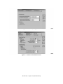
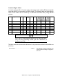
1
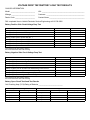
SERVICE
BULLETIN
NUMBER:
DATE:
MODEL:
SB-221-032
12/4/03
All
(Not applicable to Mack Trucks Australia)
(Supersedes bulletin SB-221-032 dated 3/20/03)
9-2 FAULT CODE DIAGNOSTICS AND REPAIR PROCEDURES
A 9-2 fault code “Power reset without Key Switch” (Failure Mode Identifier [FMI] 4,
Parameter Identifier [PID] S254 and Message Identification [MID] 128/142), will set with a
MID 142 if the Vehicle Electronic Control Unit (VECU) senses a loss of battery without the
key switch being turned off. A 9-2 fault code will set with a MID 128 if the Engine Electronic
Control Unit (EECU) senses a loss of switched power without the key switch being turned
off. Fault code 9-2 generally indicates a loss of power or ground connection to the VECU or
EECU. Complete electronic diagnostic procedures for troubleshooting a 9-2 fault code are
outlined in theV-MAC® III Service Manual, 8-211 (dated October 2001 or later). In addition
to the diagnostic procedures outlined in the V-MAC® III service manual, when
troubleshooting the cause of a 9-2 fault code, the investigation should include the following:
The following procedures cover all chassis equipped with MACK
engines and CL and CV model chassis equipped with Cummins
engines.
To avoid a repeat failure, do not stop performing the procedures
outlined in this bulletin at the point where it appears that the
problem may have been corrected. All steps (steps 1 through 8),
plus the voltage drop tests, must be performed to ensure that the
cause of the 9-2 fault code has been repaired.
1. Inspect the batteries.
a.
Load test each battery.
b.
Check tightness of each battery connection. Clean and tighten as necessary.
c.
If the vehicle is equipped with a battery disconnect switch, check the connections
for corrosion and tightness. Clean and tighten as necessary.
2. Inspect the battery cable connections at the starter motor.
a.
Before proceeding, disconnect the negative battery cables from the battery.
b.
Remove the positive and negative battery cables from the starter motor. Note the
tightness of the cable connections while they are being removed.
c.
Note any corrosion on the cable ends, then clean both sides of the cable terminal.
d.
Reinstall the battery cables and tighten the retaining nuts to 270 lb-in (31 N·m).
SB-221-032 — Page 1 of 8 (with attachment)
SERVICE PUBLICATIONS, ALLENTOWN, PA 18105
©MACK TRUCKS, INC. 2003
3. Inspect the left-side engine ground.
REV
a.
Remove the bolt that secures the ground cable to the engine block (note the
tightness of the ground bolt prior to removal). After removing the ground bolt,
discard the star washer.
b.
Clean the ring terminals of all the ground wires, and also clean the ground bolt
boss on the side of the engine block.
c.
Measure the length of the ground bolt, then measure the depth of the bolt hole in
the engine block. Compare the measurements to be sure the bolt will not bottom
in the bolt hole when tightened.
d.
Install the ground wire ring terminals onto the ground bolt, then install the bolt into
the bolt hole in the engine block. Fan the ring terminals around the ground bolt so
that the wire lugs are not on top of each other. Tighten the ground bolt to 120 lb-ft
(163 N·m).
4. Inspect the left-side frame ground.
a.
Remove the bolt that secures the ground cables and wires to the left-side frame
rail (note the tightness of the bolt prior to removal). After removing the bolt, discard
the star washer (if equipped).
b.
Inspect the bolt and the wire ring terminals for signs of arcing or corrosion.
c.
Clean both sides of the ring terminals, making sure to remove all traces of the
heat shrink sealant that may have oozed out during the heat sealing process.
d.
Clean around the ground bolt hole on both sides of the frame rail.
e.
Install the ground bolt, ground cables and wires, flat washer and nut. Fan the ring
terminals around the ground bolt so that the wire lugs are not on top of each other.
Tighten the nut to 37.5 lb-ft (51 N·m).
DO NOT use a star washer.
f.
Spray paint the area of the frame rail around the ground bolt to prevent rust from
forming.
5. Inspect the ground circuit breaker.
a.
Remove the retaining nuts that secure the cables to the terminals of the ground
circuit breaker (note the tightness of the nuts prior to removal).
b.
Discard the nuts with the captured star washers.
c.
Clean both sides of the ring terminals, being sure to remove all traces of heat
shrink sealant that may have oozed out during the heat sealing process.
d.
Install the wire ring terminals onto the terminal stud on the ground circuit breaker.
Install a new nylock nut (part No. 21AX938) onto the terminal. Fan the ring
terminals around the terminal stud so that the wire lugs are not on top of each
other. Tighten the nut to 65 lb-in (6.16 N·m).
SB-221-032 — Page 2 of 8 (with attachment)
6. Inspect the left-hand side dashboard ground wire.
a. Remove the instrument cluster and note the tightness of the ground bolt.
b. Remove the ground bolt, discard the star washer and clean all the ring terminals.
c. Sand or scrape to remove the paint from around the ground bolt hole.
d. Install a flat washer over the ground bolt, then insert the bolt through the cross bar
from the front side. Install another flat washer and secure with a prevailing torque
nut.
e. Install a flat washer over the bolt, then install the ground wire ring terminals, a flat
washer and secure with a prevailing torque nut. Tighten the nut to 108 lb-in (12
N·m).
7. Inspect the right-hand side dashboard ground.
a. Remove the “D” panel from the dashboard, then check the tightness of the ground
bolt.
b. Remove the ground bolt, discard the star washer and clean all the ring terminals.
c. Sand or scrape to remove the paint from around the ground bolt hole.
d. Install a flat washer over the ground bolt, then insert the bolt through the cross bar
from the front side. Install another flat washer and secure with a prevailing torque
nut.
e. Install a flat washer over the bolt, then install the ground wire ring terminals, a flat
washer and secure with a prevailing torque nut. Tighten the nut to 108 lb-in (12
N·m).
8. If the 9-2 code is logged in the VECU, proceed as follows:
a. Remove fuse or circuit breaker No. 16 from the electrical equipment panel.
b. Insert the purple male test lead adapter included in the Kent-Moore V-MAC® Test
Lead Adapter Kit (tool No. J 38581) into the female terminal to check the tightness
of the terminal.
c. If the drag felt on the test lead is not sufficient, replace the female terminal end
(part No. 925AM173).
d. Remove power relay Nos. 1 and 2 from the electrical equipment panel.
e. Check the terminal blades of the relays for deep scratches which indicated good
contact between the female terminals and the male terminal blades of the relays.
f.
If deep scratches are not present, inspect the female terminals for damage or
spreading. Replace the female terminals as required (part Nos. 2967-2807554
[Amp Industries part No. 280755-4] and 2967-422811 [Amp Industries part No.
42281-1]).
Although the power relays may seem tight when being removed
from the electrical equipment panel, this does not indicate
sufficient contact between the male and female terminals. The
only way of determining sufficient contact is by looking for deep
scratches on the male terminals.
SB-221-032 — Page 3 of 8 (with attachment)
9. If the 9-2 code is logged in the EECU, proceed as follows:
a.
Remove fuse or circuit breaker No. 40 from the Engine Power Distribution Module
(EPDM).
b.
Insert the purple male test lead adapter included in the Kent-Moore V-MAC® Test
Lead Adapter Kit (tool No. J 38581) into the female terminal to check tightness of
the terminal.
c.
If the drag felt on the test lead is not sufficient, replace the female terminal end
(part No. 6031-12110844).
d.
Disconnect connector “B” from the EPDM.
e.
Inspect the connector terminals for corrosion and other damage, and check to
make sure that each terminal is fully seated and locked in the connector body.
f.
Disconnect the engine-to-transmission transition connector.
g.
Inspect the terminals for corrosion and other damage, and check to make sure
that each terminal is fully seated and locked in the connector bodies.
Testing Voltage Drop
Measuring voltage drop across a cable or a cable connection is useful in determining the
integrity of the circuit. Cables or connectors should have no measurable, or only a fractional
voltage drop. For a wire, cable or connector, voltage drop should be 0.1 volt or less, and for
an insulated or ground circuit, voltage drop should be 0.5 volt or less. Voltage drop
measurements greater than 0.1 volt for a cable or connector indicate the presence of high
resistance that could be caused by a loose connection, dirt or corrosion. When diagnosing a
9-2 fault code, the following voltage drop tests should be performed, and the information
gathered from these tests should be recorded on the “Voltage Drop Test/Battery Load Test
Results” form included at the end of this service bulletin. The completed form can then be
faxed to the Mack Trucks Electronic Service Engineering Department for analysis.
Voltage Drop Test Procedures
Voltage drop is measured by placing a digital multimeter (volt-ohm meter) in parallel with the
component (wire, connection, etc.) as follows:
1. Set the multimeter to the VDC function.
2. Turn the vehicle ignition switch to the ON position.
Long jumper wires with alligator clips on both ends may be used
to facilitate performing the following tests.
SB-221-032 — Page 4 of 8 (with attachment)
3. Measure voltage drop on the positive side of the battery by placing the positive meter
lead on the positive battery post (terminal), then place the negative meter lead at the
following test points:
a.
Battery positive post to battery positive cable end
b.
Battery positive post to starter solenoid battery (B) terminal
c.
Battery positive post to starter relay battery (B) terminal
d.
Battery positive post to power relays 1, 2, 3 and 4
e.
Battery positive post to alternator positive (B) terminal
4. Measure voltage drop on the negative side of the battery by placing the positive meter
lead on the negative battery post (terminal), then place the negative meter lead at the
following test points:
a.
Battery negative post to battery negative cable end
b.
Battery negative post to starter ground terminal
c.
Battery negative post to frame ground
d.
Battery negative post to master ground circuit breaker
e.
Battery negative post to left-hand side dashboard ground terminal
f.
Battery negative post to right-hand dashboard ground terminal
g.
Battery negative post to alternator ground (G) terminal
h.
Battery negative post to left-hand side engine ground connection
5. Record the voltage drop measurements obtained at the above locations in the form
provided with this bulletin. If voltage drop measurements are higher than specified,
clean the connectors, terminals, etc., as required and retest.
In addition to the above voltage drop tests, also perform an open circuit voltage test and load
test of all the batteries. Include this information on the form provided with this bulletin.
For information concerning voltage drop tests, battery open
circuit voltage tests and battery load tests, refer to the MACK
Electrical Troubleshooting Manual, 8-212.
SB-221-032 — Page 5 of 8 (with attachment)
Multiplexing (MUX) Settings — CL and CV Model Chassis Equipped with Cummins
Engines
On CL and CV model chassis equipped with Cummins engines, the following multiplexing
(MUX) settings must be verified. These settings must be verified by an authorized Cummins
facility using INSITE™software.
1
Figure 1 — J1939 Multiplexing 1 Screen
2
Figure 2 — J1939 Multiplexing 2 Screen
SB-221-032 — Page 6 of 8 (with attachment)
3
Figure 3 — J1939 Multiplexing 3 Screen
4
Figure 4 — Features and Parameters Screen
SB-221-032 — Page 7 of 8 (with attachment)
Cummins Engine Codes
In chassis equipped with a Cummins engine, the engine control module (ECU) uses specific
codes that identify it as an engine in a MACK chassis. The following table lists these specific
codes. These codes can be viewed by an authorized Cummins facility using INSITE™
software.
SC
Engine Model
DO
FR
(PP)
CPL
AP
Torque
ECM
code
(ECM
part No.
3681405)
ECM
code
(ECM
part No.
3408426)
ECM
code
(ECM
part No.
3408501)
10682
ISX-530
1169
10409
2834
1034
1850
N11341
N11333
N11337
MACK
10426
ISX-565
1169
10515
2834
1034
1850
N10358
N10350
N11251
MACK
10425
ISX-600
1169
10311
2834
1034
1850
N10357
N10349
N11249
MACK
10423
Signature 600 STX
1169
10296
2834
1034
2050
N10356
N10348
N11246
MACK
10421
Signature 600
1168
10149
2834
1034
2050
N10355
N10347
N11244
MACK
10413
ISX-500/1650
1168
10152
2629
1034
1650
N11268
N11231
N11239
MACK
10412
ISX-500/1850
1168
10192
2629
1034
1850
N11267
N11230
N11238
MACK
10334
ISX-500 ST2
1168
10079
2629
1034
1650
N11266
N11229
N11237
MACK
On CL and CV model chassis equipped with a Cummins engine,
verify that the terminating resistor (part No. 598AX197) is
installed at the ECM.
The labor code and maximum labor allowance for the procedures outlined in this bulletin are
as follows:
230 CA 2T 80 ...........................................................
3.5 hrs. —
Time allowed to perform diagnostic and
repair procedures relating to a logged 9-2
fault code.
SB-221-032 — Page 8 of 8 (with attachment)
VOLTAGE DROP TEST/BATTERY LOAD TEST RESULTS
CHASSIS INFORMATION:
Model: ___________________________
VIN: _______________________________________________
Mileage: __________________________
Customer: __________________________________________
Dealer Code: ______________________
Contact Name: _______________________________________
FAX completed form to Vehicle Electronic Service Engineering at 610-709-3800
Battery Positive Side Circuit Voltage Drop Test
Measurement Points
Battery
Battery
Battery
Battery
Battery
Battery
Battery
Battery
First Measurement
Second Measurement
First Measurement
Second Measurement
positive post to battery positive cable end
positive post to starter solenoid B terminal
positive post to starter relay B terminal
positive post to power relay No. 1
positive post to power relay No. 2
positive post to power relay No. 3
positive post to power relay No. 4
positive post to alternator B terminal
First measurement taken before cleaning
Second measurement taken after cleaning
Battery Negative Side Circuit Voltage Drop Test
Measurement Points
Battery
Battery
Battery
Battery
Battery
Battery
Battery
Battery
negative
negative
negative
negative
negative
negative
negative
negative
post
post
post
post
post
post
post
post
to
to
to
to
to
to
to
to
battery negative cable end
starter ground terminal
frame ground
master ground circuit breaker
left-hand side dashboard ground terminal
right-hand side dashboard ground terminal
alternator ground (G) terminal
engine left-hand side ground connection
First measurement taken before cleaning
Second measurement taken after cleaning
Battery Open Circuit Test/Load Test Results
Cold Cranking Amp (CCA) Rating of Batteries ___________________________
Open Circuit Voltage Test
Voltage
Battery
Battery
Battery
Battery
1
2
3
4
Battery Load Test
Voltage
Battery
Battery
Battery
Battery
Amperage
1
2
3
4
FormSB221032 (3/20/03)