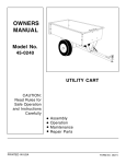
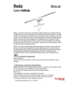
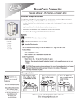
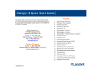
1
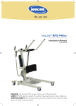
Rena 440/600
9
1
4
12
2
5
6
13
14
Rena440/600EE
Rena440EM
Rena440/600DS
1. Boom
2. Mast
3. Handlebar
4. Battery pack
5. Emergency stop
6. Control box
7. Motor for base-width adjustment
8. Rear castors with brakes
9. SlingBar with safety latch
10. Front castors
11. Emergency lowering (mechanical)
12. Motor/actuator for boom
13. Padded leg support
14. Foot rest
3
11
Manual
7
8
10
Rena 440 EM/EE/DS Max. load: 205 kg / 440Ibs
Rena 440 is a mobile sit-to-stand lift that has been developed for use in combination
with the correct lifting accessories to help the patient to stand up comfortably from a
seated position. It provides support under the feet, against the shins and behind the back.
Rena 440 is used in combination with StandUpSling.
RoMedic’s slings and lifts are part of the SystemRoMedic concept, which takes a holistic
approach to patient transfers. SystemRoMedic has four categories: transfer, repositioning,
support and lifting.
Functional inspection
Visual inspection Inspect hoist functions regularly. Check to ensure that material is free from damage.
Always read the instructions
Read instructions for all assistive devices used in connection with transfers. Keep the
manual where it is accessible to users of the product.
Do not leave the patient unattended during a lifting situation.
Before use:
Make certain the lift is properly assembled.
Lifting accessories must be properly trial fitted and tested in relation to the patient’s needs
and functional ability.
Check Slingbar connection and safety latch function.
Check lift lifting function and base-width adjustment.
Under no circumstances may the lift be used by persons who have not
received instruction in the operation of the lift.
Version 3.0d
Table of Contents
Safety Instructions
Product Description
Technical Data
Measurements 440 series
Measurements 600 series
Final Inspection
User's Guide
Charging the Batteries
Accessories
Simple Troubleshooting
Care and Maintenance
Scale (on DS model only)
3
3
4
5
6
7
8
9
10
11
12
13
Note: In this document, the person being lifted is called the “patient" and the
person helping is called the “caregiver".
“Warning!” This instruction guide contains information that is
important for users of the product. A complete understanding of the
contents of the instruction guide is essential, and only personnel who are
well informed should use the equipment. Remember to keep the instruction
guide readily accessible for users of the product.
VER 3.0D
2
07/2009
Safety Instructions
Before use make certain that:
• the lift is assembled according to the instructions.
• the lifting accessories are properly mounted on the lift.
• all instructions for both lift and accessories have been carefully studied and fully
understood.
• persons using the equipment have received appropriate instructions and training.
• the appropriate lifting accessory regarding type, size, material and design in proportion
to the patient is used following the sling manufacturers recommendations
Maximum load: 440 lbs. (200 kg)
Before lifting always make certain that:
•
•
•
•
the back belt is not damaged.
the patient is positioned firmly and securely so that no part of the body can be injured.
the back belt is properly attached to the lift hook.
This should be checked when beginning to lift the patient - when the sling straps are
taut, but the patient is still seated.
“Warning” Never leave the patient unsupervised in Rena!
Product Description
1
12
2
13
3
14
4
15
5
16
6
17
7
18
8
9
19
10
11
VER 3.0D
1. Handcontrol
2. Lift Arm
3. Handles
4. Mast
5. Battery Pack
6. Emergency Stop Button
7 Control box with built-in charger
8. Label for color code sling sizes
9. Base spread handle
10. Rear castor with brake
11. Foot Tray, removable
12. Sling Bar Safety Latch
13. Lift Hook for back belt attachment
14. Emergency Lowering Device
15. Actuator for raising and lowering
16. Lower Leg Support, adjustable
17. Lower Leg Support adjustment knob
18. Calf support strap
19. Front castor
3
07/2009
Technical Data
Lifting speed: 3,5 cm/s (1,4 inch./s) without load
Batteries: Two 12V 2.9 Ah valve-regulated
lead-acid gel-type batteries.
Battery Built-in charger, 100-230 V,
charger: max 400mA
Actuator (mast): 24 V, 6 A, permanent magnetic
actuator with mechanical safety
mechanism and safety nut.
Actuator (base): On EE/ DS models only-24 V, 3,5 A, permanent
magnetic actuator.
Material: Steel with hammer tone powder coat
Emergency lowering: Mechanical and electrical
Wheels: Front: 75 mm dual.
Rear: 100 mm with brake.
Intermittent Int. Op 10/90, active operation max 2
operation: min. Out of a time of 100, active must
be less than 10, though not more than 2 min.
Degree of protection: IP 43
Built for indoor operation.
Type B according to the degree of protection
against electric chock.
Class ll equipment.
VER 3.0D
4
07/2009
Measurements
RENA 440 series
RENA 440EM
Row A
B
F
E
A
RENA 440EE/DS
B
Row A
B
A
41.5
41.5
B
40.5
40.5
C
45
43.5
D
35
25.5
E
4.25
4.25
F
37.5 - 61
38 – 60.5
D
C
Note: Row A is measurements in inches,
Row B is measurements in cm
K
RENA 440EM
Row A
I
J
G
B
Row A
B
G
21.5 - 37
20 – 30.5
H
26 1/2 - 42
24.25 - 35
I
15.5
15.5
J
3 1/2
4.25
K
18
18
*
108 lbs.
116lbs.
* Weight of lift, A=lbs, B=kgs
Note: DS models weigh 15 lbs. more
H
VER 3.0D
RENA 44OEE/DS
5
07/2009
Measurements
RENA 600 series
RENA 600EM
Row A
B
F
E
A
RENA 600EE/DS
B
Row A
B
A
41
41
B
40
40
C
54
54
D
35.5
35.5
E
4.25
4.25
F
38.5 - 61
38.5 - 61
D
C
Note: Row A is measurements in inches,
Row B is measurements in cm
K
RENA 600EM
Row A
RENA 600EE/DS
B
Row A
B
G
26.5 - 40
28.5 – 43
H
31.5 – 44.5
33.5 – 45
I
21.5
21.5
J
4
4
J
K
18
18
G
*
133.5
149.5 lbs.
I
H
* Weight of lift, A=lbs, B=kgs
Note: DS models weigh 15 lbs. more
VER 3.0D
6
07/2009
Final Inspection
•
•
•
•
•
•
•
•
•
•
Final inspection of the lift is required
before putting the lift into service. Once
the lift has been removed from it’s
shipping pallet, inspect it for signs of
damage.
Make sure all four casters are working
properly, check castor locks (figure 1)
Inspect all connections, nuts and bolts.
Look at the packing material to see if any
loose nuts, bolts, screws are discovered. If
any are found identify where they go and
put them back on.
Turn the emergency stop button clockwise
so it pops out. (figure 2)
Now the lift should be ready for
operation. Take the hand control and push
the up bottom. Run the lift arm all the way
up. Then push the down button and run
the lift all the way down.
Verify the emergency stop button works
by pushing it in and push the up or down
button to verify the lift doesn’t work.
Follow the instructions for a sling that you
are using and lift a person (that is not a
patient) in the lift to test operation.
Verify that emergency lowering works with
someone in the lift. (figure 3)
If everything has checked out
satisfactorily, plug the lift in for charging,
verify the yellow charging light comes on.
(figure 4)
View the video in-service DVD for proper
training on the Rino before you put the lift
into use with a patient.
VER 3.0D
7
1
2
3
4
07/2009
User’s Guide
Operation
• Operate the lift using the pushbuttons on
the hand control. (figure 5)
• For raising and lowering:
Directional arrows show the direction of
movement (up/down). The lift stops when
you release the buttons.
• For base-width adjustment:
Press either of the two lower pushbuttons.
Emergency Stop
• To use the Emergency Stop:
Push the red Emergency Stop button on
the control box. (figure 6)
• To reset:
Turn the button in the direction of the
arrows.
Electrical emergency lowering
• With a narrow object that is not sharp (a
key or allen wrench), press the hole
marked "EMERGENCY" on the control box.
(figure 6, arrow is pointing at holes)
Mechanical emergency lowering
• Pull the red emergency lowering regulator
upward one inch. (figure 7) The
mechanical emergency lowering device
functions only when the lift arm is loaded,
i.e., when the patient is in the lift.
Locking the wheels
• To lock the wheels, press the brake lever
above the wheel down with your foot.
(figure 8)
• During lifting, wheels should remain
unlocked so that the lift may shift to the
patient's center of gravity. The wheels
should however be locked if there is a risk
for the lift moving into the patient, for
example when lifting from the floor.
5
6
7
8
9
Warning! Never move the lift by
pulling the actuator! (figure 9)
VER 3.0D
8
07/2009
Charging the batteries
Battery Charge Level
• Your Rena lift has three different
indicators to alert you to the charge level
of the batteries. One is a yellow LED light
on the hand control. When it remains on
when a button is depressed, the battery
has less than 25% charge left. (figure 10)
• The battery gauge is the best indicator of
charge level. When less than 1 bar
symbol, (figure 11) that indicates the
charge level is below 25%. When the
gauge appears like this it could also mean
the emergency stop button is pushed in or
the battery pack is not properly seated.
• When all fields of the display are black,
the battery is fully charged to 100%.
• The third indication the battery is low is an
audible beep as the lift is being operated.
If you hear a beeping sound, the lift is
below 25% charge level.
Charging methods
• Your Rena lift comes standard with a
built- in charger. (figure 12) Simply plug
it into a electrical outlet to charge. Verify
the green LED light comes on to indicate
the charger is receiving power. Verify the
yellow LED is on indicating charging. Lock
the wheels of the lift while it is charging.
• An optional wall mounted charger is
also available. (figure 13) Remove the
battery from the lift and seat it on the wall
mounted charger. Verify LED’s light as
stated above.
Notes
• For maximum battery life, charge
batteries often.
• Don’t allow battery charge level to fall
below 25%, it’s best to charge before the
charge level reaches 50%.
• Never charge in a wet area.
• E-Stop button must be out to charge.
VER 3.0D
9
10
11
12
13
07/2009
Accessories
StandUp Slings
• For Standup Slings and Accessories
refer to the sling guide booklet.
14
Extra Battery Pack
• Product number R9-321450, (figure 14)
Good for emergency use or with the wall
mounted charger for battery switching
Wall Mounted Charger
• Product number R9-14221 (figure 15)
Mount on wall, preferably above a counter
or service bench near an electrical outlet.
It is recommended that wall mounted
chargers be plugged into surge protecting
power strips.
StandUp Sling
• The RoMedic StandUp Sling (Figure 16)
comes in a variety of sizes from Small to
XL. The StandUp sling comes with a safety
strap and available synthetic sheepskin
padding.
Hygiene Sling
• The Hygiene sling (figure 17) can be used
with the Rena when the patient is unable
or unwilling to bear weight. With the
removal of the shin pad the rena safely
lifts and transfers the patient in the
hygiene sling to the commode from
wheelchair or beside. See your RoMedic
Representative for more information on
this procedure.
VER 3.0D
10
15
16
17
07/2009
Troubleshooting
“The lift does not
go up or down”
“The lift goes
up, but not
down” (or vice a
versa)
1. Check that the emergency stop button is not pushed in.
2. Check that the cables are connected correctly and
pushed in all the way.
3. Check that the charging cable is not connected to the
wall socket. The lift will not work when plugged in.
4. Check that the battery is charged.
5. Check that the battery is seated properly, take it off and
re-seat it.
6. If the lift still does not work, contact RoMedic distributor.
1. Check that the cables are connected correctly and
pushed in all the way. The hand control cable can appear
to be in but if it is not seated all the way, one of the
functions may not work. If you are not sure, pull it out and
push it back in firmly.
2. If lift still does not function correctly, call your RoMedic
distributor.
“The legs of the
lift won’t
operate or only
go one way.
1. Check that the cables are connected correctly and
pushed in all the way. The hand control cable can appear
to be in but if it is not seated all the way, one of the
functions may not work. If you are not sure, pull it out and
push it back in firmly.
2. If lift still does not function correctly, call your RoMedic
distributor.
“The lift
stopped in the
raised position.”
1. Check that the emergency stop button position has not
been accidentally pushed in. (see page 7, figure 6)
2. Check the battery gauge to be sure lift is charged. (page
8, figure 12) If not switch with a charged battery.
3. If steps 1 & 2 failed and you have a patient in the lift,
use the emergency lowering device to lower the patient
safely to a bed or chair. (see page 7, figure 6 & 7)
3. If lift still does not function correctly, call your RoMedic
distributor.
“The lift is
making a strange
noise.”
VER 3.0D
1. See if you can determine where the noise is coming
from, take the lift out of use and call your RoMedic
distributor.
11
07/2009
Care and Maintenance
For safe and trouble-free operation, a few routine procedures should be
performed every day the lift is used.
• Visually inspect the patient lift and check for external damage or wear.
• Check that all screws and lock nuts on the slingbar are tight.
• Check that the safety latches on the slingbar are on and work properly.
• Check the handcontrol and the lift and width movements.
• Check the emergency lowering function (both electrical and mechanical).
• Charge the battery every day the lift is used, and check charger function.
If needed, clean the lift with warm water or mild soap solution. Warning! Do
not use chemicals containing phenol or chlorine, since this may
damage the aluminum materials.
Inspection
The lift must be thoroughly inspected at least once per year. Pay particular
attention to parts that show wear, for example, joints, bolts, etc. Service must be
carried out according to RoMedic service manual and by authorized personnel.
IMPORTANT!
Repairs and maintenance may only be carried out by qualified service personnel
using original RoMedic replacement parts or equivalent.
Transportation and storage
During transportation, or when the patient lift is not to be used for some time,
the emergency stop button should be pushed in. Store the lift at a temperature
above the freezing point and at normal relative humidity (no more than 60%).
Service agreements
RoMedic recommends you to consider a service agreement for regular maintenance
and testing of your RoMedic mobile lift. Contact your local RoMedic representative for
more information.
RoMedic’s products are constantly being updated and refined. RoMedic reserves the right
to change aspects of the products without prior notice. Contact your local RoMedic
representative for the latest information and advice.
Made in USA
RoMedic Rena lifts are manufactured according to CE standards and the Linak
components meets the CE and UL standards.
Contact RoMedic
RoMedic, Inc.
PO Box 388
Ephrata, PA 17522
www.romedic.com
VER 3.0D
Toll Free:
Phone:
Facsimile:
E-mail:
888.625.4343
717.733.1444
888-691-1091
[email protected]
12
07/2009
Scale
Scale Operation
•
•
•
Hang the back belt on the lift arm and
press the ON/ZERO button to start or
zero the scale. (figure 19) You will see
the word “Zero” then it will count
backwards- 3-2-1 and end at 0.0.
Now place the backbelt on the patient
properly and stand them with their feet
on foot tray. If the scale has turned of
just push the ON/ZERO button again.
When patient is still the weight will record
and the word “hold” will appear in the
lower left corner of the display.
When weighing is complete lower patient.
•
Notes
• To change the mode from lb. Kg. Or kg
to lb. Press the LB/KG button (it will read
“conv”) and hold until the display flashes.
Release the button. (figure 20)
• If the display flashes with a weight, this
indicates that a negative weight is being
registered.
• Display turns off after one minute of
inactivity.
• Press the recall button to display the last
weight taken (over 50lbs / 22kg.). (figure
20)
• Scale capacity is determined by weight
capacity of lift, Rena 440 is 440lbs., Rena
600 is 600lbs., do not exceed capacity of
lift.
Batteries
• The scale operates on 4 AA batteries.
• To replace batteries locate battery cover
on the underside of the scale.
• Press the side tabs of the battery holder
to release and pull out.
• Replace all 4 AA batteries with new AA
batteries and reassemble. Do not mix
types of batteries (alkaline and standard)
or old batteries with new batteries.
VER 3.0D
13
18
19
21
07/2009