1
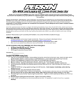
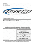
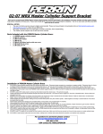
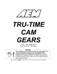
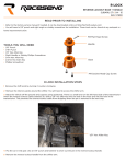
NS
REMOVAL AND INSTALLATION (Continued)
BRAKES
5 - 57
(2) Raise vehicle on jackstands or centered on a
hoist. See Hoisting in the Lubrication And Maintenance Group of this service manual.
CAUTION: Before removing the brake tubes from
the proportioning valve, the proportioning valve and
the brake tubes must be thoroughly cleaned. This is
required to prevent contamination from entering the
proportioning valve or the brake tubes.
(3) Remove the 4 chassis brake tubes from the
inlet and outlet ports of the proportioning valve (Fig.
134).
Fig. 133 Proportioning Valve Attachment To Vehicle
INSTALL
CAUTION: When mounting the original or a
replacement proportioning valve on the frame rail of
the vehicle install the mounting bolts in only the
two forward holes of the mounting bracket (Fig.
133).
(1) Install proportioning valve assembly on the
frame rail of the vehicle. Install the proportioning
valve assembly attaching bolts (Fig. 133). Tighten the
attaching bolts to a torque of 14 N·m (125 in. lbs.).
(2) Install the 4 chassis brake lines (Fig. 132) into
the inlet and outlet ports of the proportioning valve
assembly. Tighten all 4 line nuts to a torque of 16
N·m (142 in. lbs.).
(3) Bleed the brake system thoroughly enough to
ensure that all air has been expelled from the
hydraulic system. See Bleeding Brake System in the
Service Adjustments section in this group of the service manual for the proper bleeding procedure.
(4) Lower the vehicle to the ground.
(5) Road test the vehicle to verify proper operation
of the vehicles brake system.
Fig. 134 Chassis Brake Tubes At Proportioning
Valve
(4) Remove the 2 bolts (Fig. 135) attaching the
proportioning valve to the proportioning valve
mounting bracket. Remove the proportioning valve
from the mounting bracket.
PROPORTIONING VALVE (W/O ABS BRAKES)
The components of the proportioning valve assembly are not serviceable or replaceable. If a component
of the proportioning valve assembly is not functioning properly, the proportioning valve must be
replaced as an assembly.
REMOVE
(1) Using a brake pedal depressor, move and lock
the brake pedal to a position past its first 1 inch of
travel. This will prevent brake fluid from draining
out of the master cylinder when the brake tubes are
removed from the proportioning valve.
Fig. 135 Proportioning Valve Mounting
(5) Remove the hooked end of the proportioning
valve actuator (Fig. 136) from the isolator bushing on
the lever of the height proportioning valve (Fig. 136).
5 - 58
NS
BRAKES
REMOVAL AND INSTALLATION (Continued)
attach components to the front suspension cradle
have an anti—corrosion coating due to the suspension cradle being made of aluminum. Only Mopar
replacement fasteners with the required anti-corrosion coating are to be used if a replacement fastener is required when installing a brake chassis
line or flex hose.
Only double wall 4.75mm (3/16 in.) steel tubing
with Al-rich/ZW-AC alloy coating and the correct tube
nuts are to be used for replacement of a hydraulic
brake tube.
Fig. 136 Actuator Attachment To Proportioning
Valve
INSTALL
(1) Install the hooked end of the actuator on the
proportioning valve lever (Fig. 136). Be sure isola-
tor bushing on lever of proportioning valve
(Fig. 136) is fully seated in hook of actuator.
NOTE: When installing height sensing proportioning valve on mounting bracket be sure proportioning valve shield (Fig. 135) is installed between the
proportioning valve and the mounting bracket.
(2) Install height sensing proportioning valve on
mounting bracket. Install the proportioning valve
attaching bolts (Fig. 135). Tighten the attaching bolts
to a torque of 23 N·m (200 in. lbs.).
(3) Install the 4 chassis brake lines (Fig. 134) into
the inlet and outlet ports of the proportioning valve.
Tighten all 4 line nuts to a torque of 16 N·m (142 in.
lbs.).
(4) Adjust the proportioning valve actuator. See
Height Sensing Proportioning Valve in the Adjustment Section in this group of the service manual for
the adjustment procedure.
(5) Bleed the brake system thoroughly to ensure
that all air has been expelled from the hydraulic system. See Bleeding Brake System in the Service
Adjustments section in this group of the service manual for the proper bleeding procedure.
(6) Lower the vehicle to the ground.
(7) Road test the vehicle to verify proper operation
of the vehicles brake system.
HYDRAULIC BRAKE TUBES AND HOSES
CAUTION: When installing brake chassis lines or
flex hoses on the vehicle, the correct fasteners
must be used to attach the routing clips or hoses to
the front suspension cradle. The fasteners used to
NOTE: On vehicles equipped with traction control,
the primary and secondary hydraulic tubes between
the master cylinder and the hydraulic control unit
are 6 mm (15/64 in.). These tubes are also coated
with the Al-rich/ZW-AC alloy and must be replaced
with tubes having the same anti-corrosion coating.
Be sure that the correct tube nuts are used for the
replacement of these hydraulic brake tubes.
Care should be taken when replacing brake tubing,
to be sure the proper bending and flaring tools and
procedures are used, to avoid kinking. Do not route
the tubes against sharp edges, moving components or
into hot areas. All tubes should be properly attached
with recommended retaining clips.
If the primary or secondary brake tube from the
master cylinder to the ABS Hydraulic Control Unit
(HCU) or the brake tubes from the HCU to the proportioing valve require replacement, only the original factory brake line containing the flexible section
can be used as the replacement part. This is required
due to cradle movement while the vehicle is in
motion.
PARK BRAKE PEDAL MECHANISM
REMOVE
(1) Disconnect negative (ground) cable from the
battery and isolate cable from battery terminal.
(2) Remove sill scuff plate from left door sill.
(3) Remove the left side kick panel.
(4) Remove the steering column cover from the
lower instrument panel.
(5) Remove the reinforcement from the lower
instrument panel.
(6) Lock out front park brake cable using the following procedure. Grasp the exposed section of the
front park brake cable and pull rearward on it. While
holding the park brake in this position, install a pair
of locking pliers on the front park brake cable just
rearward of the second body outrigger bracket (Fig.
137).
(7) Remove the front park brake cable from the
park brake cable equalizer.