1
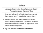
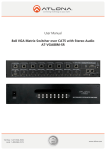
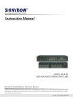
Commercial Split System
Installation Chart
6 to 121/2 Ton Condensing Units
6, 71/2 and 10 Ton Heat Pump Units
See Installation, Start-Up and Service Manual for detailed instructions and safety precautions.
TYPICAL PIPING AND WIRING
3. INSTALL REFRIGERANT PIPING
Rooftop Installation
1 - Select suction (S) and liquid (L) line size from the table below.
2 - Select refrigerant specialties.
3 - Maximum linear line length is 100 ft.
Contact applications engineering for details on lengths over 100 ft.
4 - Do not bury refrigerant piping underground.
FIELD-SUPPLIED
WEATHERPROOF
FUSED DISCONNECT
PER NEC
OUTDOOR
UNIT
MOISTURE
INDICATOR
SIGHT GLASS*
FIELDSUPPLIED
POWER
ELECTRIC
HEATER
ACCESSORY
REFRIGERANT PIPING SIZES - CONDENSING UNITS
LINEAR LENGTH OF PIPING — FT
POWER WIRES
0-25
UNIT
LLSV*
25-50
INSULATED
VAPOR
LINE
CONTROL
WIRES
6 Ton
(Single Circuit -1 Stage)
7 1/2 Ton
(Single Circuit - 1 Stage)
7 1/2 Ton
(Single Circuit - 2 Stage)
10 Ton
(Single Circuit - 1 Stage)
INDOOR
UNIT
CONDENSATE DRAIN
POWER WIRES
FIELD-SUPPLIED
FUSED DISCONNECT
PER NEC
7/ 8
or 1 1 / 8
1/ 2
7/ 8
or 1 1 / 8
7/ 8
1/ 2
10 Ton Dual Compressor
(Two Circuit - 2 Stage)
12 1/2 Ton
(Single Circuit - 1 Stage)
* Field supplied. See Refrigerant Specialties
table in “3) Install Refrigerant Piping”
section, opposite.
† Accessory Item.
L
S
1/ 2
1 1/ 8
1/ 2
1 1/ 8
or 1 / 2 7 / 8 or 1 1 / 8
1/ 2
1 1/ 8
1/ 2
or 5 / 8
1 3/ 8
1/ 2
1 3/ 8
1/ 2
or 5 / 8
(2) 3 / 8
(2) 7 / 8
(2) 3 / 8
(2) 7 / 8
1/ 2
1 1/ 8
(2) 3 / 8
(2) 7 / 8
1/ 2
1/ 2
or 5 / 8
(2) 3 / 8
1 1/ 8
(2) 7 / 8
7/ 8
L
1/ 2
S
or 5 / 8
1/ 2
1 1/ 8
1 1/ 8
or 1 1 / 8 1 / 2 or 5 / 8
1 1/ 8
1 3/ 8
1 3/ 8
1/ 2
or 5 / 8
(2) 3/8 or 1/2 (2) 1 1 / 8 (2) 3/8 or 1/2 (2) 1 1 / 8
1/ 2
or 5 / 8
1 3/ 8
1/ 2
or 3 / 4
1 3/ 8
(2) 3/8 or 1/2 (2) 1 1 / 8 (2) 3/8 or 1/2 (2) 1 1 / 8
NOTES:
1. Pipe sizes are based
on a 2°F loss for liquid
and suction lines.
2. Pipe sizes are based
on the maximum linear
length, shown for each
column, plus a 50%
allowance for fittings.
3. Charge units with
R-410A in accordance
with unit installation
instructions.
REFRIGERANT PIPING SIZES - HEAT PUMP UNITS
LINEAR LENGTH OF PIPING — FT
NOTES:
1. All piping must follow standard refrigerant piping techniques.
Refer to Product System Design Manual for details.
2. All wiring must comply with the applicable local and national codes.
3. Wiring and piping shown are general points-of-connection guides only and are
not intended for, or to include details for, a specific installation.
4. Liquid line solenoid valve (solenoid drop control) is recommended to prevent
refrigerant migration to the compressor.
5. Internal factory-supplied TXVs not shown.
0-25
25-50
50-75
75-100
Line Size (in. OD)
6 Ton
(Single Circuit -1 Stage)
7 1/2 Ton
(Single Circuit - 1 Stage)
7 1/2 Ton
(Single Circuit - 2 Stage)
10 Ton
(Single Circuit - 1 Stage)
L
S
L
S
3/ 8
7/ 8
3/ 8
7/ 8
L
3/ 8
S
or 1 / 2
L
1 1/ 8
3/ 8
S
or 1 / 2
1 1/ 8
1/ 2
7/ 8
or 1 1 / 8
1/ 2
1 1/ 8
1/ 2
1 1/ 8
1/ 2
1 1/ 8
1/ 2
7/ 8
or 1 1 / 8
1/ 2
1 1/ 8
1/ 2
1 1/ 8
1/ 2
1 1/ 8
1/ 2
7/ 8
or 1 1 / 8
1/ 2
1 1/ 8
1/ 2
1 1/ 8
1/ 2
or 5 / 8
11/8 or 13/8
CONDENSING UNIT REFRIGERANT SPECIALTIES PART NUMBERS
LIQUID LINE
SIZE (in. OD)
LIQUID LINE
SOLENOID VALVE
SOLENOID
COIL
SIGHT
GLASS
FILTER
DRIER
3/ 8
EF680033
EF680037
KM680008
KH43LG091*
1/ 2
EF680035
EF680037
KM680004
KH43LG085*
5/ 8
EF680036
EF680037
KM680005
KH43LG087*
*Bushings required.
SAFETY CONSIDERATIONS
HEAT PUMP UNIT REFRIGERANT SPECIALTIES PART NUMBERS
• Installing, starting up, and servicing air-conditioning
equipment can be hazardous due to system pressures,
electrical components, and equipment location.
• When working on the equipment, observe precautions
in the literature and on tags, stickers, and labels
attached to the equipment.
• Only trained, qualified installers and service mechanics
should install, start-up, and service this equipment.
• Follow all safety codes. Wear safety glasses and work
gloves. Keep quenching cloth and fire extinguisher
nearby when brazing. Use care in handling, rigging,
and setting bulky equipment.
• Untrained personnel can perform basic maintenance
functions such as cleaning coils. All other operations
should be performed by trained service personnel.
3/ 8
S
1
or 5 / 8 7 / 8 or 1 / 8
UNIT
LEGEND
Liquid Line Solenoid Valve
National Electrical Code
Thermostatic Expansion Valve
L
3/ 8
TO OPEN SIGHT
DRAIN
LLSV —
NEC —
TXV —
S
1/ 2
12 1/2 Ton Dual Compressor
(Two Circuit - 2 Stage)
INDOOR
THERMOSTAT†
LEGEND
L — Liquid Line
S — Suction Line
75-100
Line Size (in. OD)
L
FILTER LIQUID
DRIER* LINE
50-75
LIQUID LINE
SIZE (in. OD)
LIQUID LINE
SOLENOID VALVE
SOLENOID
COIL
SIGHT
GLASS
FILTER
DRIER
3/ 8
EF680033 plus
EF680039 biflow kit*
EF680037
KM680008
KH43LG088
1/ 2
EF680035 plus
EF680039 biflow kit*
EF680037
KM680004
KH43LG089
5/ 8
EF680036 plus
EF680039 biflow kit*
EF680037
KM680005
KH43LG090
*Bushings required.
Typical Piping for Units on the Same Level
1. INSPECT UNIT
1 - Verify that
power supply
matches unit
requirements.
2 - Inspect for
damage.
MODEL:
xxxxxxxxx
SERIAL:
xxxxxxxxx
VOLTAGE
230
Ph 3
Hz 60
15
DIAMS
MIN
8 DIAMS
MIN
OUTDOOR
UNIT
230-3-60
INDOOR
COIL
10
DIAMS
MIN
FILTER
DRIER
CORRECT?
MAX 100’
LOOK
FOR
DAMAGE?
FROM
BUILDING
LIQUID LINE
SOLENOID VALVE
(HEAT PUMP UNIT)
LIQUID LINE
SOLENOID VALVE
(CONDENSING UNIT)
Typical Piping When Indoor Unit is Above the Outdoor Unit
NOTES:
1. For applications with liquid lift
greater than 25 ft, use 1/2-in.
liquid line where 3/8 in. is
shown; use 5/8-in. liquid line
where 1/2 in. is shown.
2. Maximum liquid lift is 60 ft.
3. Dual circuit units require 2
suction and 2 liquid lines.
2. INSTALL OUTDOOR UNIT
1 - Select a location that meets
the requirements and
limitations of the refrigerant
piping recommendations
shown in next section,
“3. Install Refrigerant Piping.”
2 - Maintain adequate
clearance for airflow
and service access.
3 - Unit may be mounted on
a field-supplied pad or
support rails.
Copyright 2014 CAC/BDP
Clearances
MINIMUM
CLEARANCE
12”
VERTICAL
CLEARANCE
MINIMUM 60”
MINIMUM
CLEARANCE
36”
15
DIAMS
MIN
INDOOR
COIL
10
DIAMS
MIN
8 DIAMS
MIN
SUCTION
FILTER
DRIER
LIQUID
LIQUID LINE
SOLENOID VALVE
(CONDENSING UNIT)
60’ MAX
OUTDOOR
UNIT
AIRFLOW
LIQUID LINE SOLENOID VALVE
(HEAT PUMP UNIT)
11/14
Catalog No: 38AU-02CI
Replaces: 38AU-01CI
Continued on back
4. MAKE ELECTRICAL CONNECTIONS
5. UNIT PRE-START
LEAK TEST
WARNING
1 - Pressurize refrigerant piping; do not exceed 150 psi.
2 - Check for leaks.
Before installing or servicing system, always turn off main power to system
and install lockout tag on disconnect. There may be more than one
disconnect switch. Electrical shock can cause personal injury.
150 PSI MAX
POWER WIRING
DRY
NITROGEN
1 - Verify that power is off, locked out and tagged off.
2 - Route power wiring from disconnect through opening in unit end panel and
connect in unit control box as shown on the unit label diagram.
ACCESS PANEL
POWER WIRING
ENTRY
SUCTION LINE
OUTDOOR
UNIT
INDOOR
COIL
LIQUID LINE
SOLENOID VALVE
TXV
LIQUID LINE
NEC
DISCONNECT
OUTDOOR
COIL
POWER
WIRES
SOAP
THERMOSTAT
WIRING ENTRY
LEFT SIDE VIEW
EVACUATION
Transformer Wiring
CONTROL WIRING
CAUTION
1 - Verify that power is off,
locked out and tagged off.
Outdoor unit contains a partial factory charge of R-410A, review
rating plate for exact charge amount. Opening liquid line ball valve
prior to charging will release holding charge.
2 - Transformer wiring:
If supply voltage is
208 v or 400 v, move the
black wire to the
appropriate terminal.
SUCTION LINE
OUTDOOR
UNIT
3 - Make connections from
thermostat to terminal strip
(TB) in the outdoor unit.
LIQUID LINE
500
TERMINAL STRIP TB
Single Compressor/1 Stage Condensing Unit
THERMOSTAT
MICRON
GAUGE
Dual Compressor/2 Stage Condensing Unit
TB
THERMOSTAT
TB
R
R
R
R
Y1
Y1
Y1
Y1
Y2
LLSV
IFC
C
G
G
C
C
INITIAL CHARGING – UNIT OFF
LLSV2
IFC
G
C
X
IFC
LLSV
TB
—
—
—
X
LEGEND
Indoor Fan Contactor
Liquid Line Solenoid Valve
Terminal Board
IFC
LLSV1
LLSV2
TB
—
—
—
—
EVACUATE TO A MINIMUM OF 500 MICRONS.
Y2
LLSV1
G
1 - After evacuating the system, fill the li quid line with R-410A (tank upside down),
Then open both service valves.
LEGEND
Indoor Fan Contactor
Liquid Line Solenoid Valve Circuit No. 1
Liquid Line Solenoid Valve Circuit No. 2
Terminal Board
OPEN
SUCTION LINE
Single Compressor/2 Stage Condensing Unit
THERMOSTAT
OPEN
TB
R
R
Y1
Y1
Y2
Y2
G
LLSV
IFC
LIQUID LINE
C
X
—
—
—
TB
Heat Pump, Single Compressor/2 Stage Unit
THERMOSTAT
TB
R
R
R
R
G
Y1
G
Y1
Y1
W1
W1
W2
LLSV1
W2
—
—
—
LEGEND
Indoor Fan Contactor
Liquid Line Solenoid Valve
Terminal Board
Y2
Y2
W1
W2
LLSV1
W2
IFC
X
C
Y1
W1
G
C
IFC
IFC
LLSV
TB
OPEN
LEGEND
Indoor Fan Contactor
Liquid Line Solenoid Valve
Terminal Board
Heat Pump, Single Compressor/1 Stage Unit
THERMOSTAT
R-410A
Add 80% of system
refrigerant capacity
or minimum 9 lb R-410A.
G
C
IFC
LLSV
TB
1000
C
IFC
LLSV
TB
—
—
—
G
C
X
LEGEND
Indoor Fan Contactor
Liquid Line Solenoid Valve
Terminal Board
TRIM CHARGE LEVEL
1 - After system has been started
and allowed to stabilize, adjust
refrigerant level, if required,
basedon the Cooling Charging
Chart found on unit and
in Installation Instructions.
2 - Check superheat at the
compressor; superheat
should be 8 to 12°F.
? ºF
ELECTRONIC
THERMOMETER
OPEN
CLOSED
R-410A
PRE START-UP TIPS
• Read Installation, Start-Up, and Service manual.
• Use start-up checklist.
• Check all wiring connections.
• Open service valves.
• Turn on power for indoor and outdoor sections.
• Energize crankcase heater for 24 hours prior to start-up.
• Make sure compressor(s) can move freely on mounting snubbers or springs.
IMPORTANT: Units with Copeland compressors may be
equipped with Advanced Scroll Temperature Protection.
Refer to the Installation, Start-Up, and Service manual
for additional information.
OPEN