1
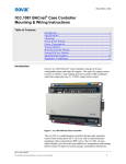
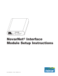
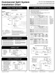
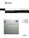
Part # RCC-RUI RCC.RUI Remote Display User Manual Table of Contents Introduction ......................................................................................1 Overview ..........................................................................................4 Test Mode Set-up for Different Valve Types ..................................7 Default Sequences of Operation ....................................................12 TEST MODE Run Time Cycles/ States.........................................14 TEST MODE Default Alarms .......................................................16 Using TEST MODE.......................................................................17 Normal Operating Mode ................................................................19 Appendix 1: Using Multiple RUI’s with RCC-1081 Mode 4 .......21 Appendix 2: RCC.RUI Remote Display Quick Start Guide ........24 Introduction RCC-RUI refers to Refrigeration Case Controller – Remote User Interface. It is the user interface for RCC-1081 refrigeration case controller. In this document is may be referred to simply as the RUI. RCC-RUI User Manual 4/13/2015 For the latest technical documentation, visit www.novar.com/manuals Part # RCC-RUI Setting the address of the RUI (RUI Revision 2 or greater): When the RUI display unit is powered up for the first time, it will display “rAd” until it has an address assigned. Press the Enter button. The default address of “1” will be flashing. Press and hold the Enter button for at least 2 seconds until the address stops flashing. The address is now set. After the address is set, you can read it again by pressing the “Back” button and the right arrow button for about 2 seconds. The address will be displayed and shown as long as the buttons are held. When the buttons are released, the RUI returns to normal display. To clear the address of an RUI, press and hold the “Enter” and left arrow buttons at the same time for about 6 seconds. The display will return to “rAd”, allowing you to re-set the address. You do not need to set an address in an RUI with a revision less than 2. It will only work as a “master” (address 1) display. NOTE: The only time the RUI is assigned an address other than 1 is when the RCC-1081 is in mode 4. For multiple RUI set-up in mode 4, refer to Appendix 1 of this manual. Initial Operation of the RCC-1081: When the RCC-1081 case controller is powered up for the first time, it comes up in the “Test Mode” (displayed as tSt on the display). The Test Mode will only appear in the display when the RCC-1081 has not yet received a program download from a Novar executive module (XCM). After it receives a download, the test mode disappears and can only be restored if the module is reset to factory default values (from the Run menu). The Test mode is intended to be used in 2 special situations: a) During installation – the test mode can be used to by Original Equipment Manufacturers (OEM’s) during factory installation to force outputs on and off, read sensors, and test basic operation. If the RCC-1081 is field installed, this mode can also be used by the system installer during the initial start up of a refrigeration mechanical system at an End User site. b) Emergency Service Operation - when all else fails, the test mode can be used by service personnel to handle emergency situations to clear the internal program of the RCC-1081 and manual override operation put into effect. This is done by resetting it to factory default values via the “reset” command that is in the Run menu. Once reset, the Run menu will only show the state of the digital outputs and allow them to be overridden. Output points can be RCC-RUI User Manual 4/13/2015 For the latest technical documentation, visit www.novar.com/manuals 2 Part # RCC-RUI forced into desired states, but they will stay that way until manually changed, or if the RCC-1081 receives a program download from a system Executive Control Module like the Opus XCM. Upon first entering the Test Mode: You must go thru the menus and enter all the required information to initially configure it for the type of valve controlled, type of refrigerant used, etc. In this mode you can also go into the network menu (nEt) to enter network communication information such as baud rate and address. When in this mode the “Run” menu will only show the state of the outputs and allow them to be overridden. Upon completion of the initial Test Mode configuration, additional parameters and operational modes become available allowing the user to view all process variables and alarms, as well as providing the ability to toggle individual digital outputs ON or OFF for troubleshooting purposes. IMPORTANT: There is no case air temperature control when in TEST MODE. Detailed explanations of available Test Mode functions are described later in this document while the sections that follow outline the basic number of steps required to initialize TEST MODE based on the type of refrigeration valves that are connected. NOTE: Once the RCC-1081 receives a program download via BACnet communications and the Multi-state variable 0 (MSV0 - APP mode) is set to anything other than zero (0), the test mode will no longer appear in the RUI Display. RCC-RUI User Manual 4/13/2015 For the latest technical documentation, visit www.novar.com/manuals 3 Part # RCC-RUI Overview Figure 1. Status LEDS The RCC-RUI Remote User Interface is a multi-purpose user interface allowing RCC-1081 Case Controller users to view and modify some, but not all, configurable parameters within a RCC-1081 Case Controller. Its primary function is to display operational status of its associated controller and refrigerated display case while also allowing local TEST MODE configuration of stepper valve and digital output connections useful for stand-alone case commissioning and trouble shooting. The following are some key features and things to remember when using the RCC-RUI: The RCC-RUI keypad may be Enable/Disabled remotely from the Opus Executive controller. The RCC-1081Case Controller default mode out of the box is to have the RCC-RUI keypad Enabled Many configurable parameters require the entry of a 3-digit PIN number before a modification is allowed. The default PIN number is 222. When connected to a configured RCC-1081 the RCC-RUI will display the Case’s Blended Air Temperature control parameter during normal operation. The Blended Air Temperature is configurable to use only the Discharge Air temp, Return Air temp, or a definable blend of Discharge and Return Air temps. It will display it however it has been configured. To view a parameter, use the LEFT and RIGHT ARROWS to scroll side-to-side through the available MENU columns and the RCC-RUI User Manual 4/13/2015 For the latest technical documentation, visit www.novar.com/manuals 4 Part # RCC-RUI UP and DOWN ARROWS to scroll up-and-down through each parameter name. When the name of the MENU or parameter you want to view/change is located, press ENTER once to view its value. Press BACK to go back one step. To change a parameter, press and hold ENTER for 2-3 seconds until the display begins flashing. Modify the parameter using the UP or DOWN ARROWS and then press and hold ENTER again for 2-3 seconds to save the changed parameter. BACnet Network Configuration Step-by-Step Figure 2. BACnet Network Configuration Setting RCC-1081 BACnet network parameters using the RCC-RUI Use the LEFT or RIGH ARROWS to move through the menu columns until ‘nEt’ is displayed Press ENTER Press the UP or DOWN ARROWS to scroll through the available parameters until you reach the parameter you want to view or change. Press ENTER to view the parameter or press BACK to return back to the name of the parameter To change a parameter, press and hold ENTER for 2-3 seconds until one of more of the parameter’s digits begin to blink. To abort a change, press the BACK button which will cause the digits to stop blinking and return to showing the current value. For Max Number of Masters ‘nnS’ or the BACnet Address RCC-RUI User Manual 4/13/2015 For the latest technical documentation, visit www.novar.com/manuals 5 Part # RCC-RUI ‘Adr’ the 1’s digit will start blinking. Use the LEFT or RIGHT ARROWS to move the blinking digit to the left or right and the UP or DOWN ARROWS to increment or decrement the blinking digit value. After all three digits are set to the desired value, press and hold ENTER for 2-3 seconds to save the new ‘nns’ or ‘Adr’ value. For Baud Rate ‘bdr’ all the digits will be blinking. Press the UP or DOWN ARROWS to scroll through the available selections. 96 = 9600 baud 192 = 19.2K baud 384 = 38.4K baud 576 = 57.6K baud 768 = 76.8K baud When the desired value is reached, press and hold ENTER for 2-3 seconds until the RCC-1081 Controller has accepted the new value and the digits stop blinking. The RCC-1081 controller will then reset itself and begin to use the new parameter values. RCC-RUI User Manual 4/13/2015 For the latest technical documentation, visit www.novar.com/manuals 6 Part # RCC-RUI Test Mode Set-up for Different Valve Types Figure 3 Test Mode initialization with Mechanical TXV or Secondary Loop LLSV RCC-RUI User Manual 4/13/2015 For the latest technical documentation, visit www.novar.com/manuals 7 Part # RCC-RUI Figure 4 Test Mode initialization with Stepper Electronic Expansion Valve (EEV) RCC-RUI User Manual 4/13/2015 For the latest technical documentation, visit www.novar.com/manuals 8 Part # RCC-RUI RCC-RUI User Manual 4/13/2015 For the latest technical documentation, visit www.novar.com/manuals 9 Part # RCC-RUI Figure 5 Test Mode Initialization with Pulse EEV RCC-RUI User Manual 4/13/2015 For the latest technical documentation, visit www.novar.com/manuals 10 Part # RCC-RUI Figure 6 Test Mode initialization with Stepper EEPR RCC-RUI User Manual 4/13/2015 For the latest technical documentation, visit www.novar.com/manuals 11 Part # RCC-RUI Default Sequences of Operation Until the RCC-1081 receives program changes thru either the RUI or via BACnet communications, the following is a description of the sequence of operation: Defrost Operation: If Electric Defrost Selected Fans are OFF during defrost Defrost termination temperature = 50.0 deg F Maximum defrost time = 30 minutes Terminate defrost on temperature with time as backup If Air/Off-Cycle Defrost Selected Fans are ON during defrost Defrost termination temperature = 40.0 deg F Maximum defrost time = 40 minutes Terminate defrost on time If Hot Gas Defrost Selected Fans are OFF during defrost RCC-RUI User Manual 4/13/2015 For the latest technical documentation, visit www.novar.com/manuals 12 Part # RCC-RUI Defrost termination temperature = 50.0 deg F Maximum defrost time = 10 minutes Terminate defrost on temperature with time as backup Control Valves: LLSV, TXV, Stepper EEV or Pulse EEV Temperature Input #2 is set to Discharge Air Temperature Temperature Input #3 is set to Defrost Termination Temperature Relay output #1 is set to Lights relay Relay output #2 is set to LLSV1 relay Relay output #3 is set to Defrost relay Relay output #4 is set to Fans relay Relay output #5-#7 are Unused Relay output #8 is set to Anti Sweat relay unless Refrigeration Control Valve Type is Pulse EEV Sequences of Operation (cont.) Superheat Control If DX System with EEV and Superheat Control Type = Pressure-Temp Universal input #1 is set to Suction Pressure If refrigerant = R-744 then pressure range is 0-500 psig If refrigerant = R-410a then pressure range is 0-300 psig If any other refrigerant selected then pressure range is 0150 psig Temperature Input #1 is set to Suction Temperature If DX System with EEV and Superheat Control Type = Temp-Temp Universal input #1 is set to Coil Inlet Temperature) Temperature Input #1 is set to Coil Outlet Temperature Circuit Control If Refrigeration Control Valve Type = EEPR If the number of Cases/Evaporators is equal to 1 Relay output #1 is set to Circuit Lights pilot relay Relay output #2 is set to Circuit LLSV1 relay Relay output #3 is set to Case #1 Defrost relay Relay output #8 is set to Circuit Fans pilot relay Universal input #6 is set to Case #1 Discharge Air Temperature Universal Input #1 is set to Case #1 Defrost Termination Temperature If the number of Cases/Evaporators is greater than or equal to 2 Relay output #4 is set to Case #2 Defrost relay Universal input #7 is set to Case #2 Discharge Air Temperature Universal Input #2 is set to Case #2 Defrost Termination Temperature If the number of Cases/Evaporators is greater than or equal to 3 Relay output #5 is set to Case #3 Defrost relay RCC-RUI User Manual 4/13/2015 For the latest technical documentation, visit www.novar.com/manuals 13 Part # RCC-RUI Temperature input #1 is set to Case #3 Discharge Air Temperature Universal Input #3 is set to Case #3 Defrost Termination Temperature If the number of Cases/Evaporators is greater than or equal to 4 Relay output #6 is set to Case #4 Defrost relay Temperature input #2 is set to Case #4 Discharge Air Temperature Universal Input #4 is set to Case #4 Defrost Termination Temperature If the number of Cases/Evaporators is equal to 5 Relay output #7 is set to Case #5 Defrost relay Temperature input #3 is set to Case #5 Discharge Air Temperature Universal Input #5 is set to Case #5 Defrost Termination Temperature TEST MODE Run Time Cycles/ States The RCC-1081 will never be in an OFF Cycle/State or CLEAN Cycle during TEST MODE REFRIGERATION Cycle/State: LLSV1 is energized If EEPR or SFV (Secondary Fluid Valve) is selected, either valve is fully open. Defrost relay or relays are de-energized Fan relay is energized If EEV is selected, modulate flow to control superheat to set point When defrost interval times out, (default 6 hours), it will enter PUMP DOWN mode PUMP DOWN Cycle/State: LLSV1 is de-energized If EEPR or SFV (Secondary Fluid Valve) is selected, either valve is fully closed. Defrost relay or relays are de-energized Fans relay is energized If EEV is selected, valve is fully closed. When pump down timer times out, (default 3 minutes), will enter DEFROST DEFROST Cycle/State: LLSV1 is de-energized If EEPR or SFV (Secondary Fluid Valve) is selected, either valve is fully closed. If air/off time defrost is selected Defrost relay is de-energized RCC-RUI User Manual 4/13/2015 For the latest technical documentation, visit www.novar.com/manuals 14 Part # RCC-RUI Else Defrost relay or relays are energized If Fans Off During Defrost is selected Fans relay is de-energized Else Fans relay is energized If EEV is selected, valve is fully closed. When max defrost timer times out, based on AV56, will enter a DRAIN Cycle/State If the Refrigeration Control Valve Type is not an EEPR If Terminate Defrost on Temperature is enabled and the defrost termination temperature is greater than the Defrost Termination Temperature set point, The RCC-1081 will enter the DRAIN Cycle/State. If Defrost Termination Temperature sensor alarm is active, the RCC-1081 will enter a DRAIN Cycle/State when the Max Defrost Timer times out. If Refrigeration Control Valve Type = EEPR If Terminate Defrost on Temperature is enabled o Then when any of the enabled Defrost Termination Temperatures (Case #1, Case #2, Case #3, Case #4, Case #5) is greater than Defrost Termination Temperature set point, turn off the corresponding Case defrost heater relay When all Defrost Termination Temperatures are greater than the Defrost Termination Temperature set point, the RCC-1081 will enter DRAIN mode If any Defrost Termination Temperature sensor alarm is active, the RCC-1081 will enter a DRAIN Cycle/State when the Max Defrost Timer times out. DRAIN Cycle/State: LLSV1 is de-energized If EEPR or SFV (Secondary Fluid Valve) is selected, either valve is fully closed. Defrost relay or relays are de-energized Fans relay is de-energized If EEV is selected, valve is fully closed. When drain timer times out (default 2 minutes), the RCC-1081 will enter FAN DELAY mode FAN DELAY Cycle/State: LLSV1 is energized If EEPR or SFV (Secondary Fluid Valve) is selected, either valve is fully opened. Defrost relay or relays are de-energized Fans relay is de-energized If EEV is selected, modulate flow to control superheat to set point When Max Fan Delay Timer times out (default to 3 RCC-RUI User Manual 4/13/2015 For the latest technical documentation, visit www.novar.com/manuals 15 Part # RCC-RUI minutes) the RCC-1081 will enter REFRIGERATION mode If the Defrost Termination Temperature is greater than Max Fan Delay Temperature set point (default to 20.0 deg F) the RCC-1081 will enter REFRIGERATION mode If defrost termination temperature sensor alarm is active, the RCC-1081 will enter REFRIGERATION mode when Max Fan Delay Timer times out. TEST MODE Default Alarms All alarms, except for the BACnet Communication Alarm, are disabled at power up. Then when certain Sensors Inputs or Digital inputs are enabled due to the default TEST MODE settings the associated alarms for that sensor are automatically enabled by the RCC-1081 because these alarms have a RCC-1081 Controller action or default associated with them other than just reporting the alarm. All other alarms must be specifically enabled by the user in order to have them available. The possible default alarms in TEST MODE are: Suction Pressure Sensor Alarm (SPA) Suction Temperature Sensor Alarm (StA) Discharge Air Temperature Sensor Alarm (AtA) Return Air Temperature Sensor Alarm (rtA) Defrost Termination Temp Sensor Alarm (dtA) Coil Inlet Temperature Sensor Alarm (CiA) Coil Outlet Temperature Sensor Alarm (COA) Refrigerant Leak Sensor Alarm (LdA) High Refrigerant Leak Alarm (rLA) Door Open Alarm (dOA) Air Temperature Sensor Alarms Case #1 to #5 (A1A…A5A) Defrost Termination Temperature Sensor Alarm Case #1 to #5 (d1A…d5A) RCC-RUI User Manual 4/13/2015 For the latest technical documentation, visit www.novar.com/manuals 16 Part # RCC-RUI Using TEST MODE Figure 7 Alarm in test mode RCC-RUI User Manual 4/13/2015 For the latest technical documentation, visit www.novar.com/manuals 17 Part # RCC-RUI Figure 8 Run in test mode RCC-RUI User Manual 4/13/2015 For the latest technical documentation, visit www.novar.com/manuals 18 Part # RCC-RUI Figure 9 Pro in test mode Normal Operating Mode During normal operation of the RCC-11081 Controller (in all configuration Modes except the Mode #6 Remote I/O Mode) the RCCRUI will display the following information in the following priority order: #1: Display any alarms that are present #2: Display “dEF” if in defrost, drain, fan delay or pull-down cycle. Continue to display dEF until Air Temperature reaches set point or 15 minutes has elapsed after fan delay. #3: Display Air Temperature value being used by the RCC-1081 RCC-RUI User Manual 4/13/2015 For the latest technical documentation, visit www.novar.com/manuals 19 Part # RCC-RUI Controller. When in configuration Mode #6 the RCC-RUI display will normally be blank if there is no User Defined value written to it and will display “Err” is if there is a BACnet Communications Failure alarm. If no display button is pressed within 60 seconds, the display will go back into the Normal display mode and the User’s PIN will be 222. RCC-RUI User Manual 4/13/2015 For the latest technical documentation, visit www.novar.com/manuals 20 Part # RCC-RUI Appendix 1: Using Multiple RUI’s with RCC1081 Mode 4 Overview Mode 4 of the RCC-1081 is for control of a circuit’s EEPR valve. If the EEPR is located near the cases, and if the cases use conventional TXV’s (non-electronic), then a single RCC-1081 can drive 5 RUI’s to monitor up to 5 case temperatures. Each RUI will display the discharge air and defrost termination temperature sensors of its associated case. The multiple displays are connected via an RCC-RUI Hub, and each must be set up with a unique address. An example for this equipment set-up is as follows: EEPR Figure 10 Example shows 4 cases, but up to 5 are supported In this drawing the EEPR, the 4 displays, and associated temperature sensors are all connected to 1 RCC-1081 operating in Mode 4. The cases have conventional TXV’s. Refer to the installation instructions for connecting multiple displays via an RUI Hub. NOTE: Multiple displays can only be used with an RCC-1081 configured for Mode 4. If used in any application other than Mode 4, RUI’s with addresses greater than 1 will display an error message of “diS” (disabled, no temperature associated with this address). RCC-RUI User Manual 4/13/2015 For the latest technical documentation, visit www.novar.com/manuals 21 Part # RCC-RUI NOTE: If using mode 4 with multiple displays, the minimum RCC1081 version is 1.26 and the minimum RUI version is 2.0. Setting the RUI address when used in Mode 4 In order to uniquely display the temperature of each case in the line-up, an address must be set in each display. Display address 1 will read the first discharge air temperature and the first defrost termination sensor (input numbers 6 and 1, respectively); display address 2 will read the second discharge air temperature and second defrost termination sensor (inputs 7 and 2, respectively), etc. The method of setting an RUI address is as follows: When first connected to the RUI Hub, the display will read “rAd” (RUI address). To change the address, use the up and down arrows. To save the desired address, press and hold the Enter button for at least 2 seconds. After the address is set, you can read it again by pressing the “Back” button and the right arrow button for about 2 seconds. The address will be displayed and shown as long as the buttons are held. When the buttons are released, the RUI returns to normal display. To clear the address of an RUI, press and hold the “Enter” and left arrow buttons at the same time for about 6 seconds. The display will return to “rAd”, allowing you to re-set the address. The display that is set to address 1 will go into the network and test mode setup, as described in this document beginning on page 6. The display will show either “tSt” or “nEt” to reflect these modes. RUI’s with addresses >1 will begin to display their temperatures. Error Messages for “slave” RUI’s (those with an address >1) AxA = Air Temperature sensor alarm (the one matched to the display address). dxA = Discharge Temperature sensor alarm (the one matched to the display address). PrF = The display is not communicating properly with the RCC1081. diS = The temperature sensors associated with this display are disabled. NOTE: These are the only alarms that will display on slave RUI’s. Other alarms only display on the “master” RUI (address 1). RCC-RUI User Manual 4/13/2015 For the latest technical documentation, visit www.novar.com/manuals 22 Part # RCC-RUI Additional Comments: 1. The BACnet communication alarm LED only functions on the master RUI (address 1). Therefore, if the RCC-1081 loses BACnet communication, it will only be indicated on the master RUI. 2. The sensor status LED functions on all RUI’s, but only for the sensors associated with its address. 3. There is no indication of an RUI address conflict. Multiple addresses with display the same information. 4. In mode 4, all RUI’s display only their associated temperatures. The control temp (hi, low, average, or blended air temp) can be viewed via the menus of RUI-1. RCC-RUI User Manual 4/13/2015 For the latest technical documentation, visit www.novar.com/manuals 23 Part # RCC-RUI Appendix 2: RCC.RUI Remote Display Quick Start Guide RCC-RUI User Manual 4/13/2015 For the latest technical documentation, visit www.novar.com/manuals 24 Part # RCC-RUI RCC-RUI User Manual 4/13/2015 For the latest technical documentation, visit www.novar.com/manuals 25 Part # RCC-RUI RCC-RUI User Manual 4/13/2015 For the latest technical documentation, visit www.novar.com/manuals 26 Part # RCC-RUI Opus™ is a trademark of Honeywell International Ethernet® is a registered trademark of Xerox Corporation MODBUS® is a registered trademark of Schneider Electric AX Niagara is a registered trademark of Tridium NovarNet® is a registered trademark of Honeywell International The material in this document is for information purposes only. The content and the product it describes are subject to change without notice. Novar makes no representations or warranties with respect to this document. In no event shall Novar be liable for technical or editorial omissions or mistakes in this document, nor shall it be liable for any damages, direct or incidental, arising out of or related to the use of this document. No part of this document may be reproduced in any form or by any means without prior written permission from Novar. Copyright © 2015 by Honeywell International, Inc.. All Rights Reserved. Novar 6060 Rockside Woods Blvd., Cleveland, OH 44131 Phone: 1.800.348.1235 www.novar.com RCC-RUI User Manual 4/13/2015 For the latest technical documentation, visit www.novar.com/manuals 27