1
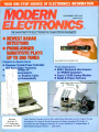
NOVEMBER 1985 $1.95
CANADA $2.50
TM
THE MAGAZINE FOR ELECTRONICS & COMPUTER ENTHUSIASTS
NEWEST RADAR
DETECTORS
PHONE-RINGER
SUBSTITUTE PLAYS
UP TO 200 TUNES
Projects & Applications
Computer System Power Controller
with Surge -Spike Protection
Bridge for
leasurements
i or Brighten Lights
nd Automatically
Automobie Radar Detectors
(p. 22:
First impressions
GEM's Macintosh -Like Graphics
for MSDOS Computers
Kapro's 16 -Bit Laptop Machine
Health & Fitness Software
"9VIelb.Phone" Super
M
usical Telephone Ringer (p. 36.
Keypo 2000 Laptop
Bulk Rate
Permit No. 79
U.S. Postage Paid
Gordonsville, VA 22942
Plus: Testing Yamaha's Do -lt -All Audio /Video Receiver and an 8 -Input Scope
Using A Word Processor to Make Isometric Drawings
Multiplexer
Latest Satellite TV Happenings
International SW Program Updates
Electronic /Computer News ... and more.
C-R7 IL' CC
sc
mom.
F,
+.e.M-
+.r,-
x.'.
.i.rr
-
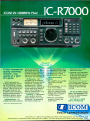
ICOM's commercial
quality scanning
receiver..Sop
quality at a gem
of a price.
ICOM introduces the
IC-R7000 advanced technology 25- 2000MHz* continuous coverage communications
receiver. With 99 owner programmable memories, the
IC -R7000 covers low band,
aircraft, marine, business, FM
broadcast, amateur radio,
emergency services, government and television bands.
Keyboard Entry. For
simplified operation and quick
tuning, the IC-R7000 features
direct keyboard entry. Precise
frequencies can be selected by
pushing the digit keys in sequence of the frequency or by
turning the main tuning knob.
99 Memories. The
IC -R7000 has 99 memories
available to store your favorite
frequencies, including the
operating mode. Memory
channels may be called up by
simply pressing the Memory
switch, then rotating the
memory channel knob, or by
direct keyboard entry.
Scanning. A sophisticated
scanning system provides
instant access to most used
frequencies. By depressing
the Auto-M switch, the
I
C -R 7000
automatically memo-
Optional RC -12 infra -ed
remote controller
Optional voice synthesizer.
When recording, the voice
synthesizer automatically
announces the scanred
rizes frequencies in use while
the unit is in the scan mode.
This allows you to recall
frequencies that were in u;
Other Outstanding
signal frequency.
Features:
FM wide/FM narrow/Aff,/
upper and lower
15
*Specifications guaranteed
from 25- 1300MHz. Nc additional module required for
coverage to approximately
SSB
modes
tuning speeds: 0.1, 1.0,
or 25KHz
Dual color fluorescent disSix
5, 10, 12.5
2.0G Hz.
play with memory channel
readout and dimmer switch
Compact Size: 4 -3/8 "H
x 111/4"W x 1078 "D
Dial lock, noise blanker,
combined S -meter and
center meter
See the IC-R7000 receiver
at your local authorized ICOM
dealer. Also available is the
IC -R71Á 0.1 -30MHz general
coverage receiver.
ALL THIS AT A PRICE
YOU'LL APPRECIATE.
CIRCLE 178 ON READER SERVICE CARD
GIU
First
/
M
ICOMj,
Com
nications
,
75234
ICOM America, Inc., 2380-116 Ave NE. Bellevue, WA 98004 3331 Towervvood Drive, Suite 307, Dalla
S
All stated specifications are approximate and subject to change sattis out notice or obligation. Ali ICOM radios significantly exceed FCC regulations limiting spurious emissions. rtseoo885
Do You REALLY Want to Make More Money?
MAKE_
Yes it does take work and a few sacrifices to
climb up the electronics ladder to where the bigger
money is. But, if that's where you want to be, then
that's what you must do work harder at learning
and getting the right credentials, even if it takes a
few sacrifices. A B. S. degree and the knowledge
that rightly goes along with it can give you powerful
ladder -climbing equipment in your search for success in electronics.
The accredited Grantham non -traditional B.S.
Degree Program is intended for mature, fully employed workers who want to upgrade their electronics careers.
-
ELECTRONICS
You say you're already trained in electronics
but that you're not making enough money???
Well then, maybe you don't have an accredited
bachelor's degree to prove that your education
is up to snuff/ Check out the Grantham Independent -Study B. S. Degree Program. It could
make a dollars and sense difference in your
electronics career.
Grantham offers this program, complete but
without laboratory, to electronics technicians
whose objectives are to upgrade their level of
technical employment. Since the field of electronics is so enormous, opportunity for advancement is always present. Promotions and
natural turnover make desirable positions
available to the man who is ready to move up.
Grantham College of Engineering
10570 Humbolt Street
Los Alamitos, California, 90720
Put Professional Knowledge and a
COLLEGE DEGREE
in your Electronics Career through
Independent Home Study
Study materials, carefully written by the Grantham
College staff for independent study at home, are
supplied by the College. Your technical questions
related to these materials and the lesson tests are
promptly answered by the Grantham home -study
teaching staff.
Recognition and Quality Assurance
is accredited by
National Home
of
the
the Accrediting Commission
Study Council, as a degree -granting institution.
Grantham College of Engineering
All lessons and other study materials, as well as communications between the college and students, are in the
English language. However, we have students in many
foreign countries; about 80% of our students live in the
United States of America.
for
FREE
Booklet
This free booklet
explains the
Grantham B.S.
Degree Program,
offered by independent study to
those who work
in electronics.
CLIP
COUPON
r10570 Humbolt Street,
Los
Alamitos, CA 90720
Please mail me your free catalog which explains your
B.S. Degree independent -study program.
and mail in
Name
envelope or
paste on
Address
postal
card.
M -9-85
Grantham College of Engineering
LCity
Age
State
September 1985
/
Zip
MODERN ELECTRONICS
/
1
RN
EL
EDITORIAL STAFF
1S
THE MAGAZINE FOR ELECTRONICS & COMPUTER ENTHUSIASTS
NOVEMBER 1985
VOLUME 2, NUMBER 5
Art Salsberg
Editor -in -Chief
Alexander W. Burawa
Managing Editor
Dorothy Kehrwieder
Production Manager
Elizabeth Ryan
Art Director
FEATURES
22
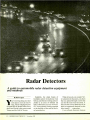
Radar Detectors
A guide to automobile radar detectors
and methods. By Ron Cogan
28
RCA Goes Ku -Band
Three new satellites serve TV broadcasting,
business and TVRO viewers. By Stan Prentiss
34
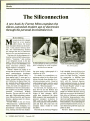
The Siliconnection
New book explores modern age of electronics.
By Art Salsberg.
36
50
42
44
50
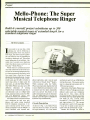
Mello- Phone: Super Musical
Telephone Ringer
Project substitutes up to 200 musical tunes for
standard telephone ringer. By Steve Lympany
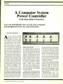
A Computer System Power Controller
(with Surge -Spike Protection)
Individually turn on /off computer and
peripherals from one central location.
By Paul M. Spannbauer
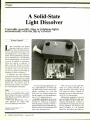
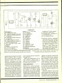
A Solid -State Light Dissolver
Smoothly dim or brighten lights automatically
with flip of a switch. By Imre Gorgenyi
A Simple Impedance Bridge
Two-component project lets you measure impedance, determine resonant frequency, etc.
By William R. Hoffman
36
53
Army Wrist Receiver
Helps soldiers locate assembly points.
54
"Absolute Reset" for Newest Apple Its
Update info you need to use the Apple Ile Absolute
Reset with the new "enhanced" IIe and 11c.
By Don Lancaster
PRODUCT EVALUATIONS
10
Yamaha R -9: Do -it -all
Audio /Video Receiver
By Len Feldman
86
42
Global Specialities Model 8001
Scope Multiplexer
Gives
8
inputs to 2-channel scopes. By Stan Prentiss
DEPARTMENTS
4
Editorial
Buying By Mail. By Art Salsberg
SPEED
56
Letters
Modern Electronics News
New Products
Electronics Notebook
64
Hardware Hacker
4
6
10
CHECKED
EY
RADAR
Barbara Scully
Artist
Pat Le Blanc
Richard Kishanuk
Phototypographers
Hal Keith
Illustrator
Larry Mulvehill
Photographer
Leonard Feldman, Glenn Hauser,
Don Lancaster, Forrest Mims III,
Stan Prentiss, Charles Rubenstein
Contributing Editors
BUSINESS STAFF
Richard A. Ross
Publisher
Art Salsberg
Associate Publisher
Dorothy Kehrwieder
General Manager
Anthony C. Sparacino
Newsstand Sales Director
Arlene Caggiano
Accounting
Cheryl Chomicki
Subscriber Services
SALES OFFICES
Modern Electronics
76 North Broadway
Hicksville, NY 11801
(516) 681 -2922
Eastern Advertising Representative
Paul McGinnis Company
60 East 42nd Street
New York, NY 10017
(212) 490 -1021
Midwest Advertising Representative
Market /Media Associates
435 Locust Road
Wilmette, IL 60091
(312) 251-2541
Ted Rickard
Western Advertising Representative
JE Publishers Representatives
6855 Santa Monica Blvd., Suite 200
Los Angeles, CA 90038
(213) 467 -2266
Jay Eisenberg, Director
San Francisco: (415) 864 -3252
Denver: (303) 595 -4331
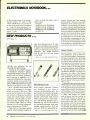
Pressure-Sensitive Resistors. By Forrest M. Mims III
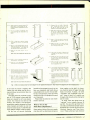
Bar codes, fiber -optics goodies, isometric drawings,
and more. By Don Lancaster
70
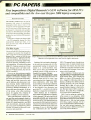
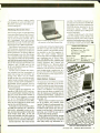
PC Papers
Digital Research's GEM software and Kaypro 2000
laptop computer. By Eric Grevstad
72
Software Focus
Health and Fitness Programs.
By Charles M. Salsberg
74
Communications
International SW Program Updates.
By Glenn Hauser
77
94
22
2
/
MODERN ELECTRONICS
/
Books & Literature
Advertisers Index
November 1985
Offices: 76 North Broadway, Hicksville, NY 11801. Telephone: (516) 681 -2922. Modern Electronics (ISSN 07489889) is published monthly by Modern Electronics, Inc.
Application to mail at second class rates pending at
Hicksville, NY and other points. Subscription prices
(payable in US Dollars only): Domestic - one year $16.97,
two years 831.00, three years $45.00; Canada /Mexico
-one year 819.00, two years $35.00, three years 851.00;
Foreign - one year 821.00, two years $39.00, three years
$57.00. Foreign Air Mail - one year S74.00, two years
$145.00, three years $216.00.
Entire contents copyright 1985 by Modern Electronics,
Inc. Modern Electronics or Modern Electronics, Inc. assumes no responsibility for unsolicited manuscripts. Allow six weeks for delivery of first issue and for change of
address. Printed in the United States of America.
Postmaster: Please send change of address notice to
Modern Electronics, Inc., 76 North Broadway, Hicksville, NY 11801.
ftadie Ihaek Parti PIaee
-,
The Builder's Store! Over 1000 Items in Stock
Add Synthesized Speech Output to Your Computer Timer IC Project Book and Parts
(3)
(2)
(1)
1
1
Audio
Amp
Text -to-Speech IC
Voice Synthesizer
Synthesizer IC SP0256 -AL2. Uses
programming stored in its built -in 16K ROM to
synthesize natural sounding speech. Easy to interface with most microcomputers. Requires lowcost support components and 3.12 MHz clock
crystal (available through Radio Shack). 28-pin
DIP with detailed specs and programming data.
12.95
#276-1784
(2) Text -to- Speech IC CTS256 -AL2. Preprostandard
grammed 8 -bit processor translates
ASCII characters into control data for the synthe(1) Voice
sizer above. Makes
it a
snap to add voice output
to virtually any personal computer or
ASCII terminal. 40 -pin DIP with complete data,
schematics. Requires 10 MHz crystal (available
16.95
through Radio Shack). #276-1786
(3) Audio Amplifier IC LM386. Requires a minimum of support components. Perfect as an audio
output stage for speech synthesizer. 400 mW output. Adjustable gain. 4 to 12 VDC. 8 -pin DIP.
1 09
#276 -1731
Computer/Game Connectors
Solder DIP Sockets
Low As
199
Cat. No.
276 -1995
276 -1999
276 -1998
Price
2/59¢
2/89¢
2/89¢
Type
Cat, No.
276 -1992
276 -1991
276 -1989
276 -1997
276 -1996
Each
.49
.59
.79
.89
.99
20 -Pin
24 -Pin
28 -Pin
40 -Pin
Type
Solder Sub -D Male
Solder Sub -D Female
Hood for Above
Solder Sub -D Male
Solder Sub -D Female
Hood for Above
Printer Connector
[Card -Edge Connector
Current
6.3
300 mA
273 -1384
2.59
Miniature
12.6
300 mA
273 -1385
2.79
Miniature
25.2
300 mA
273 -1386
3.49
Miniature
12.6 CT
450 mA
273-1365
3.59
Miniature
25.2 CT
450 mA
273-1366
3.99
1.2 A
273 -1351
3.99
1.2 A
273 -1352
4.99
uF
0.1
6.3
Standard
Each
Standard
12.6 CT
Standard
25.2
1.2 A
273 -1353
5.99
Heavy-Duty
12.6 CT
273 -1511
6.99
Heavy -Duty
25.2 CT
3.0 A
2.0 A
273 -1512
7.49
Heavy -Duty
18.0 CT
2.0
273 -1515
6.99
CT
9
9
25
25
25
36
34
Cat. No.
276-1537
276-1538
276-1539
276 -1547
276-1548
276-1549
276 -1534
276 -1564
Each
1.99
2.49
1.99
2.99
3.99
1.99
4.99
4.95
Learn the Basics of
"Lightwave" Links
Optical Fiber Cable. 3-meter (approx. 9 ft.) length of
5 99
high -quality optical fiber cable. #276 -228
Infrared Emitter/Detector Set. Use to send analog or
digital signals through fiber optic cable. No special
tools or hardware required for assembly. Application
4 99
notes included. #276-225 ....
Switch and Relay Values
(5)
Miniature
Volts
9
Primaries
Cat. No.
Type
Positions
Tantalum Capacitors
Power Transformers
120 VAC
Experiment With Fiber Optics
2
Type
8 -Pin
14-Pin
16 -Pin
18 -Pin
A
1195
IC
Low As
59e
Pkg. of
99c
Mini- Notebook. Learn how to use the versatile 555 and 556 timer ICs by building your own circuits.
Written in simple language by Forrest Mims III. Large
99C
schematic diagrams. 32 pages. #276-5010
Timer Project Parts. For above. Requires #276 -174
11.95
breadboard and 9V battery. #277-061
Timer
= Center tap
(7)
(6)
(4)
496
Low As
Maximum capacity n a very small size. Standard IC pin spacing. 20% tolerance.
0.47
WVDC
35
35
1.0
2.2
35
35
16
16
10
22
Cat. No.
272 -1432
272 -1433
272 -1434
272 -1435
272 -1436
272 -1437
Each
.49
.49
.49
.59
.69
.79
(4) Micro -Mini SPOT Relay. Just
it/32 x 3/8 x' /x' Contacts: 1 amp at 125
....
1.99
VAC. 12 VDC coil. #275 -241
(5) Mercury Switch. Rated 5 amps at 125 VAC. Style may vary.
1 19
#275 -027
(6) Illuminated Round SPDT Push -On Switch. 3 amps at 120
VAC. Lamp requires 12 volts AC /DC. Mounts in '/2" hole.
4 95
#275 -677
(7) Illuminated SPST Normally Open or Closed Switch. 5
amps at 250 VAC. Lamp requires 12 volts AC /DC. With red and
5.95
green lenses. Mounts in 5/e" hole. #275 -678
.
We Can Replace Almost Any Industrial SALE! 16 -Range LCD Digital
Reg. 49.95
Or Entertainment IC or Semiconductor
Save $10
RADIO SHACK'S NEW
SPECIAL -ORDER SERVICE
Multitester
3995
Easy to Use
C:ompact Size
Fused and Overload Protected
Diode /Semiconductor Test Mode
No Minimum Order!
No Postage Charge!
Really Convenient!
Step up to digital accuracy and the convenience
of full auto-polarity operation at big savings! The
high-contrast liquid crystal display features lowbattery and over-range indicators. Measures up
to 1000 volts DC, 500 volts AC, 2 amps DC and 2
megohms resistance. There are four ranges for
each function. Includes test leads, owner's manual and spare fuse. 53/16 x 31/4 x17/16': Batteries
Sale 39.95
extra. #22 -189
Protective Case for Above. #22- 153.. 5.95
semiconductor you need is not
part of our regular stock, our store manager
will check our new in -store substitution guide
and then special -order a replacement from
our warehouse. Your order will be sent to
your Radio Shack store and we'll notify you
when it arrives. There's no postage to pay or
other extra charges for this convenient service! Visit our store near you for details.
If the IC or
Over 1000 items in stock: Binding posts. Books. Breadboards, Buzzers, Capacitors. Chokes. Clips.
Connectors, Fuses, Hardware, ICs, Jacks, Knobs. Lamps, Multitesters. PC Boards, Plugs, Rectifiers, Relays, Resistors, Switches, Tools, Transformers, Transistors. Wire, Zener Diodes. and more!
Radie ihaek
A DIVISION OF TANDY CORPORATION
Prices apply at participating Radio Shack stores and dealers
CIRCLE
48 ON FREE
INFORMATION CARD
November 1985
/
MODERN ELECTRONICS
/
3
LETTERS
11111111/EDITORIAL 1111111111=1
Buying By Mail
I'm writing to correct an error in "Portable Computers '85," in the August issue. His statement that the TRS -80 Model
200 doesn't support PEEK, POKE, or
CALL statements in BASIC is wrong.
The Model 200 supports all the BASIC
commands available to the Model 100,
with a few additions and improvementsas
well. Other than that error, I thought his
article was well-written, and fairly presented the computers mentioned.
A recent addition to the laptop group is
the Spectravideo Bondwell, a 64K CP/M
computer with 80 x 24 line LCD display,
built -in 360K 3.5 " disk drive, 8 -hour rechargeable battery supply and bundled
software (Wordstar, Calstar, Datastar,
Reportstar, Xmodem, Scheduling program, and several public-domain utilities). It is the only laptop that has a flip top screen designed for field use: it has a
180 -degree angle of freedom instead of
stopping at a preset vertical angle (you
can open the display to a horizontal position). Its best feature is its price: $999.95
(Bondwell International, 3300 Seldon
Court, Fremont, CA 94539).
While I'm writing, thanks for resurecting the original concept behind the now defunct Popular Electronics. I used to
subscribe to it way back when.
Terry Kepner
Peterborough, NH
Not For Export
*The David Wolf article on AkihabaraAn Electronics Shopper's Paradise-was
well -done, and certainly intriguing at this
side of the pond. It certainly appeared
that the electronics buyer can find some
remarkable products at very low prices to
bring back to the USA.
However, when it comes to amateur radio equipment, U.S. amateur -radio companies like Kenwood and Yaesu are dead
set against their imported equipment
coming back to the States by hams trying
to save a buck. Some of their equipment is
listed on a Customs blacklist that disallows its entry into the States. A student of
mine recently had to send his new Kenwood 940 transceiver back on the same
charter flight he brought it in on because
Customs would not permit its import.
There are also many subtle frequency
and power differences between Japanese
and United States-destined equipment.
One student save $100 on his handie
(Continued on page 91)
4
/
MODERN ELECTRONICS
/
Many billions of dollars are spent each
year in mail -order purchases. In the electronics and computer fields, this mode of
doing business has grown enormously for
a variety of reasons. Firstly, no single
store could ever stock the vast variety of
parts and equipment on the market today. Furthermore, selling prices by mail order companies are generally well below
those of local stores for the same product.
There are tradeoffs, of course. For example, many electronic mail -order companies have minimum orders of, say, $10,
whereas local stores don't. Also, you pay
modest shipping and handling charges
when you order by mail. Nonetheless,
low prices and parts /equipment availability usually make up for these shortcomings if you want more than just one or
two resistors. The slight delay in getting
products bought is a small cross to bear
for most people.
But what do you do if there is an unreasonable delay in receiving your order, for
which you've paid up front? And what do
you do should there be a rotten apple in
the barrel? Unlike a local store, you can't
confront someone who might be a thousand miles away. Moreover, a state's laws
can't protect you when dealing with
someone in another state.
Should you ever be faced with such
problems, you should know that you do
indeed have special protection in mail order transactions. The Federal Trade
Commission has a Trade Regulation Rule
relating to mail -order merchandise, as an
example. The civil penalty for violating
the Rule is up to $10,000 per violation
(each day of failure to comply with the
Rule may be treated as a separate violation). In addition, the FTC can also sue
for consumer redress.
Let's examine the Rule now, which was
set up to protect consumers who buy by
mail and to build up trust and confidence
in mail-order transactions.
*Shipment of a properly completed
order must be made within 30 days after
its receipt unless shipment time is clearly
and conspicuously noted in a solicitation
(e.g., "Allow 5 weeks for delivery. ").
Many companies ship within a day or
two.
*If a shipment is delayed, the seller
must send you a notice within 30 days
after receiving the order, or before the
shipping time noted in the solicitation,
that gives you a revised shipping date or
November 1985
notice that a shipping date cannot be determined-plus an option to cancel your
order.
The notice should also provide you
with a satisfactory way to respond, such
as a prepaid post card or an "800" toll free telephone number that can be readily
and consistently used. You should also be
advised that non -response is considered
consent to a delay of 30 days or less.
If the revised shipping date is more
than 30 days after the original date or it's
stated that a shipping date cannot be determined, your order should be automatically cancelled if merchandise isn't shipped within 30 days of the original date, or
you can cancel beforehand, unless you respond that you consent to the new shipping delay date. If you inform the seller
that you agree to an indefinite shipping
delay, you still have the right to cancel at
any time prior to shipping.
*Refunds must be sent to you by first
class mail within seven days after the
order is cancelled, except that credit card
charges may be refunded within one billing cycle. (The reasoning here is fair since
you haven't laid out any money yet.)
A few other FTC rulings you should
know about are: Credit vouchers or script
are no substitutes for a refund; the Rule
does not cover you for using a credit card
by telephone only, without going through
the mail; merchandise cannot be substituted that's different from what you ordered without your authorization; the
seller's receipt of a properly completed
order can be construed to mean the time
at which he gets notice that a check or
money order for the proper amount has
been honored. The Rule doesn't cover all
mail -order activities. There are a few exceptions, which include magazine subscriptions and similar serial deliveries, excepting the first shipment; sales of seeds
and growing plants; C.O.D. orders;
transactions covered by the FTC's "Negative Option Rule," such as book and
record clubs; and mail -order photo -finishing (considered to be a service, not
merchandise).
Should you have a serious problem
with any mail -order house, you can send
your complaint to the Federal Trade
Commission, Enforcement Division,
Washington, D.C. 20580.
Fraud is another story, of course. Here
you have recourse to the U.S. Attorney's
(Continued on page 82)
NEW!
NEW!
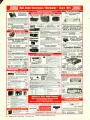
J I L SX-400- K
List price $799.95/CE price $489.00 /SPECIAL
NEW! Bearcat® 800XLT -K
Frequency range: 26 -520 MHz continuous coverage.
With optionally equipped RF converters 150KHz -3.7 GHz.
The JIL SX -400 synthesized scanner is designed for
commercial and professional monitor users that demand features not found in ordinary scanners. The SX400 will cover from 150 KHz to 3.7 GHz. with RF
converters. Order the following RF converters for your
SX -400 scanner. RF- 1030 -K at $259.00 each for
frequency range 150 KHz. -30 MHz. USB, LSB, CW and
AM. (CW filter required for CW signal reception); RF5080-K at $199.00 each for 500 -800 MHz.; RE-8014 -K
at $199.00 each for 800 MHz.-1.4 GHz. Be sure to
also order ACB-300 -K at $99.00 each which is an
antenna control box for connection of the RF converters.
The RC-4000 -K data interface at $259.00 each gives
you control of the SX -400 scanner and RF converters
through a computer. Add $3.00 shipping for each RF
converter, data interface or antenna control box. If you
need further information on the JIL scanners, contact
Bands: 29 -54, 118 -174, 406 -512, 806 -912 MHz
The Uniden 800XLTreceives 40 channels in two banks.
Scans 15 channels per second. Size 9'6" x4V x 12'/2."
Multi-Band, 20 Channel No-crystal Scanner
Search
Lockout Priority AC/DC
UD1EIE!fl®
Fkolntiant-
Scanners
Communications Electronics,
JIL directly at 213 -926-6727 or write JIL at 17120
Edwards Road, Cerritos, California 90701 U.S.A.
SPECIAL! JIL SX-200-K
List price
price
$159.00
$499.95/CE special
-18 Channel No-Crystal Scanner
the world's largest distributor of radio Multi-Band
Frequency range 26 -88, 108 -180, 380-514 MHz.
scanners, introduces new scanners The JIL SX-200 scanner tunes military, F.B.I., Space
Police and Fire, Drug Enforcement Agencies,
and scanner accessories from J.I.L., Satellites,
Defense Department, Aeronautical AM band, Aero
Regency and also Uniden /Bearcat. Navigation Band, Fish & Game, Immigration, Paramedics,
Radio, Justice Department, State Department,
Chances are the police, fire and Amateur
plus other thousands of radio frequencies most other
weather emergencies you'll ' read scanners can't pick up. The SX-200 has selectable
/FM receiver circuits, tri- switch squelch settings about in tomorrow's paper are coming AM
signal, audio and signal & audio, outboard AC power
through on a scanner today.
supply - DC at 12 volts built -in, quartz clock - bright
NEW! Regency/ MX7000 -K
List price $699.95/CE price $429.00/SPECIAL
10-Band, 20 Channel
Crystalless
AC /DC
Frequency range: 25-550 MHz. continuous coverage
and 800 MHz. to 1.2 GHz continuous coverage
In addition to normal scanner listening, the
MX7000 offers CB, VHF, and UHFTV audio, FM
Broadcast, all aircraft bands (civil and military),
800 MHz communications, cellular telephone,
and when connected to a printer or CRT, satellite
weather pictures.
NEW! Regency® MX5000 -K
List price $599.95/CE price $329.00 /SPECIAL
Multi-Band, 20 Channel No-crystal scanner
Search Lockout Priority AC/DC
Selectable AM-FM modes LCD display
World's first continuous coverage scanner
Frequency range: 25 -550 MHz continuous coverage.
Never before have so many features come in
such a small package. The Regency MX5000
mobile or home scanner has continuous coverage from 25 to 550 MHz. That means you can
hear CB, Television audio, FM broadcast stations, all aircraft bands including military and
the normal scanner bands, all on your choice of
20 programmable channels.
NEW! Regency® MX4000 -K
List price $629.95/CE price $299.00/SPECIAL
Multi-Band, 20 Channel No-crystal scanner
Search Lockout Priority AC /DC
Selectable AM-FM modes LCD display
Bands: 30-50,118-136,144-174,440-512,800-950 MHz
The Regency MX4000 is gives coverage in the
standard VHF and UHF ranges with the important addition of the 800 MHz. and aircraft bands.
It features keyboard entry, multifunction liquid
crystal display and variable search increments.
NEW! Regency° Z60 -K
List price $379.95/CE price $216.00 /SPECIAL
8 -Band, á0 Channel
No-crystal scanner
Bands: 30-50, 88 -108, 118-136, 144 -174, 440-512 MHz.
Cover your choice of over 15,000 frequencies
on 60 channels at the touch of your finger.
vacuum fluorescent blue readouts and dimmer, dual
level search speeds, tri -level scan delay switches, 16
memory channels in two channels banks, receive fine
tune (RIT) ± 2KHz., dual level RF gain settings -20 db
pad, AGC test points for optional signal strength meters.
Regency® HX1000 -K
List price $329.95/CE price $209.00
8-Band, 30 Channel No Crystal scanner
Lockout Priority
Search
Scan delay
Sidelit liquid crystal display
Digital Clock
Frequency range: 30 -50, 144 -174, 440 -512 MHz.
The new handheld Regency HX1000 scanner is fully
keyboard programmable for the ultimate in versatility. You can scan up to 30 channels at the same time.
When you activate the priority control, you automatically override all other calls to listen to your favorite
frequency. The LCD display is even sidelit for night
use. Order MA -256 -K rapid charge drop -in battery
charger for $79.00 plus $3.00 shipping /handling.
Includes wall charger, carrying case, belt clip,
flexible antenna and nicad battery. Order now.
NEW! Bearcat® 100XL -K
List price $349.95/CE price $229.00
0-Band, 16 Channel Priority Sean Delay
Search
Limit Hold Lockout AC/DC
Frequency range: 30-50, 118-174, 406 -512 MHz.
The world's first no-crystal handheld scanner now has
a LCD channel display with backlight for low light use
and aircraft band coverage at the same low price. Size is
136" x 7'/2" x 27/8:' The Bearcat 100X L has wide frequency
coverage that includes all public service bands (Low,
High, UHF and "T' bands), the AM aircraft band, the 2meter and 70 cm. amateur bands, plus military and
federal government frequencies. Wow...what a scanner!
Included in our low CE price is a sturdy carrying case,
earphone, battery charger /AC adapter, six AA ni -cad
batteries and flexible antenna. Order your scanner now.
NEW! Regency° HX2000 -K
The World's First800 MHz. Handheld Scanner
List price $569.95/CE price $359.00
7 -Band, 20 Channel
No-crystal scanner
Priority control Search/Scan AC/DC
Sidelit liquid crystal display Memory backup
Bands: 118 -136, 144 -174, 440 -512, 800 -950 MHz
The HX2000 scanner operates on 120V AC or 6 VDC.
Scans 15 channels per second. Size 3" x 7" x 1'/2."
Includes wall charger, carrying case, belt clip, flexible
antenna,and nicad batteries. Selectable AM /FM modes.
List price $499.95/CE price $329.00
12-Band, 40 Channel
No-crystal scanner
Priority control Search/Scan AC/DC
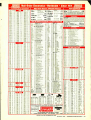
OTHER RADIOS AND ACCESSORIES
Panasonic RF- 2600-K Shortwave receiver
Panasonic RF -B300-K Shortwave receiver
R D95 K Uniden Remote mount Radar Detector
RD55 -K Uniden Visor mount Radar Detector
BC 20/20 -K Bearcat 40 channel scanner
$179.00
$195.00
$139.00
$119.00
$274.00
BC 21 OXW -K Bearcat 20 channel scanner
$219.00
BC -WA-K Bearcat Weather Alert$39.00
DX1000 -K Bearcat shortwave receiver
$459.00
PC22 -K Uniden remote mount CB transceiver
$99.00
PC55 -K Uniden mobile mount CB transceiver
$59.00
Z10 -K Regency 10 channel scanner
$139.00
230 -K Regency30 channel scanner
$154.00
Z45 -K Regency45 channel scanner
$179.00
R1060-K Regency 10 channel scanner
$98.95
MX3000 -K Regency 30 channel scanner
$189.00
0403-K Regency 4 channel scanner
$69.00
R106-K Regency 10 channel scanner
$99.00
R H250 B-K Regency 10 channel VHF transceiver ... $329.00
R U150 B-K Regency 10 channel UH F transceiver ... $449.00
RPH410 -K 10 ch. handheld no-crystal transciever... $399.00
BC1 o -K Battery charger for Regency RPH410
$79.00
MA256 -K Drop-in charger for HX1000 scanner
$79.95
MA257 -K Cigarette lighter cord for HX1000
$19.95
MA917 -K Ni-Cad battery pack for HX1000
$24.95
EC1 O -K Programming tool for Regency RPH410
$20.00
SMRH250 -K Service man. for Regency RH250
$20.00
SMRU150-K Service man. for Regency RU150
$20.00
SM R PH4I O-K Service man. for Regency RPH41 O
$20.00
SMMX7000 -K Svc. man. for MX7000& MX5000:
$20.00
SMMX3000-K Service man. for Regency MX3000 $20.00
B -4 -K 1.2 V MA Ni -Cad batteries (set of four)
$9.00
A- 135C -K Crystal certificate
$3.00
FB-E -K Frequency Directory for Eastern U.S.A.... $12.00
FB-W -K Frequency Directory for Western U.S.A... $12.00
TSG -K "Top Secret" Registry of U.S. Govt. Freq.... $15.00
TIC-K Techniques for Intercepting Comm
$15.00
RRF -K Railroad frequency directory
$10.00
CIE -K Covert Intelligenct, Elect. Eavesdropping
$15.00
A60-K Magnet mount mobile scanner antenna
$35.00
A70-K Base station scanner antenna
$35.00
USAM M -K Mag mount VHF/UHF ant. w/ 12' cable
$39.95
USAK -KAY." holemountVHF /UHF ant. w/ 17' cable
$35.95
$35.95
USATLM -K Trunk lip mount VHF /UHF antenna
Add $3.00 shipping for all accessories ordered at the same time.
Add $12.00 shipping per shortwave receiver.
Add $7.00 shipping per scanner and $3.00 per antenna.
BUY WITH CONFIDENCE
get the fastest delivery from CE
of any scanner,
send or phone your order directly to our Scanner
Distribution Center" Michigan residents please add 4%
sales tax or supply your tax I.D. number. Written purchase orders are accepted from approved government
agencies and most well rated firms at a 10% surcharge
for net 10 billing. All sales are subject to availability,
acceptance and verification. All sales on accessories
are final. Prices, terms and specifications are subject to
change without notice. All prices are in U.S. dollars. Out
of stock items will be placed on backorderautomatically
unless CE is instructed differently. A $5.00 additional
handling fee will be charged for all orders with a
merchandise total under $50.00. Shipments are F.O.B.
Ann Arbor, Michigan. No COD's. Most products that we
sell have a manufacturer's warranty. Free copies of
warranties on these products are available prior to
purchase by writing to CE. Non -certified checks require
bank clearance.
To
Mail orders to: Communications Electron-
ics," Box 1045, Ann Arbor, Michigan 48106
U.S.A. Add $7.00 per scanner for U.P.S. ground
shipping and handling in the continental U.S.A.
For Canada, Puerto Rico, Hawaii, Alaska, or
APO /FPO delivery, shipping charges are three
times continental U.S. rates. If you have a Visa
or Master Card, you may call and place a credit
card order. Order toll -free in the U.S. Dial
800 -USA-SCAN. In Canada, order toll-free by
calling 800 -221 -3475. Telex CE anytime, dial
810- 223 -2422. If you are outside the U.S. or in
Michigan dial 313- 973-8888. Order today.
Scanner Distribution Center" and CE logos are trademarks of Communications Electronics Inc.
t Bearcat is a registered trademark of Uniden Corporation.
*Regency is a federally registered trademark of Regency
AD í/090385 -K
Electronics Inc.
Copyright o 1985 Communications Electronics
For credit card orders call
1- 800 - USA-SCAN
Regency
RH250
MCOMMUNICATIONS
ELECTRONICS INC.
Consumer Products Division
MX4000
HX2000
CIRCLE
26 ON FREE
MX7000
INFORMATION CARD
P.O. Box 1045 O Ann Arbor, Michigan48106 -1045 U.S.A.
Call 800-USA-SCAN or outside U.S.A. 313-973 -8888
November 1985
/
MODERN ELECTRONICS
/
5
1111111/MODERN ELECTRONICS
NEWS
Ill/Ill
M68000 DESIGN KIT. A design kit with MC68000 and MC8008 microprocessors and six supporting devices, as well as application notes and documentation, is being offered by Motorola's Micro Products Div. through
its distributors for $68.
THE PICOCASSETTE.
Dictaphone Corp. introduced the smallest magnetic
tape medium, moving from a microcassette to a picocassette.
Measuring
only 1.42" x 0.98" x 0.18" and weighing 1 oz., it has a recording capacity
of a full 60 minutes of dictation and other voice applications.
It's
being used in the company's newest protable recorder, Model 4250 Exec.
CHRYSLER USES BAR CODES. Chrysler Corp. changes electronics component
suppliers' business ways by now requiring them to label automotive parts
containers with bar -coded information.
Other auto makers will follow,
all using CODE 39, the bar code chosen by the Automotive Industry Action
Group as a standard in the industry.
JUSTICE DEPT. SLAMS RF INTERFERENCE VIOLATORS. The U.S. Dept. of Justice
recently announced actions against people who unlawfully operated radio broadcast equipment. It's suing one person for $900 in accumulated fines
for refusing to allow his Citizens Band Radio equipment to be inspected
as a result of many complaints from neighbors about TV interference.
Inspectors claim that the user was exceeding the maximum power level.
In a similar case, where 40 complaints were registered, an FCC engineer
determined that the culprit was putting out 47 watts, which is 43 past
the maximum allowed.
Suit was filed for $750.
A third case charged a
company with interfering with TV reception for 18 months due to computer generated signals. Accumulated fines for failing to shield the computer
to eliminate interference were $3,000.
CONSUMER ELECTRONIC PRODUCT PRICES DROP. Notwithstanding typical inflationary increases in just about everything, prices of consumer electronic equipment prices continue to decrease. Compact Disc players,
for example, dipped from an average dollar value of $429 in 1983 to
about $280 in 1985; tabletop VCRs from $470 in 1983 to $375 in 1985;
color TV receivers from $386 in 1980 to $330 in 1985; programmable video
games from $116 in 1982 to $43 in 1985; home computers from $650 in
1982 to $500 in 1985; telephones (corded) from $54 in 1982 to $31 in 1985.
UNIVERSITY COMPUTERS. Hewlett - Packard has developed programs on artificial intelligence (AI) at U.S. universities to foster basic research
in this important computer area.
It expects to grant about 600 workstations to 12 to 15 universities, with each receiving a license for
prototype AI software developed by HP Labs.
It has already announced
grant awards to Massachusetts Institute of Technology and the University
of Utah.
Northeastern University's Bay Area Regional Tech Center
reports that the Assosciation for Continuing Education Instructional TV
Network will televise four of the institution's state -of- the -art engineering courses to member -company employees starting September 23 with
System Reliabiltiy Engineering.
Other courses announced are Intro to AI,
Intro to Data Communications, and Principles of Telecommunications.
.
6
/
.
MODERN ELECTRONICS
/
November 1985
Your guide to everything that's new in electronics. computers and technical
educatior. Over 4)0 terns Discover
fascinating kits tc bLiid, enjoy and learn
with, as well as assemblec high tech procu is
for hcme, business end hobby.
r--
1
Heath Corr pany
C opt. 079 54
Bentcn Ha mor, Michigan 49022
MAIL COUPON TODAY and re, Bide the latest
issue of the Healhkit Catalog tree o- cierge
Name
CLE
51
ON FRZ3 INFORMATION CARD
Heathkíf
Heath
Compcny
A subsi
iiary of zalth Electronics Cor 'oration
Addres s
3a-e
C ty
CL -783C
Zip
Will/NEW PRODUCTS/Ill/li
For more information on products
described, please circle the appropriate number on the Free Information
Card bound into this issue or write to
the manufacturer.
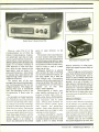
first laptop computer to incorporate
this ROM -based software package.
The computer measures 13 "W x
11'h'D x 13/4"H and weighs 7.7 lbs.
$1995.
CIRCLE NO.
145 ON
FREE INFORMATION CARD
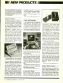
Laptop Computer
The Heath Company is offering an
assembled MS- DOS -compatible disk less laptop computer. The Model
ZP -150 computer is built around a
low -power 80088 microprocessor,
32K of RAM (expandable to 416K),
224K of ROM containing a raft of
applications software, and an
80- column by 16 -line LCD screen.
Built -in interfaces include a parallel
printer port, an RS-232 serial port,
audio cassette player port, and a telephone jack that is used with the internal 300 -baud modem. These interfaces, the RESET switch, and the ac
adapter jack are located on the rear
of the computer, behind a drop down protective panel.
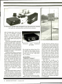
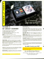
Video Title Generator
A new keyboard -type title generator
from RCA can be used with just
about any make video camera. It lets
you create on tape up to 60 characters
at a time on a scene in any of four
character sizes. Characters can be
stored in the Model CGA010 generator's battery -powered memory for
several months, and up to 40 frequently used words can be stored in
the word register.
This titler can also store and recall
up to 20 groups of characters in either
page -at -a -time or scroll forward/
Programmed into the ZP -150's
on -board ROM are six business oriented applications programs developed by Microsoft. Known as the
"Works" integrated software package, it consists of Plan, a subset of
MultiPlan; Word, a subset of Microsoft's Word processor; File, a new
Data Base Management System
(DBMS); Calendar appointment secretary; Telcom telecommunications
package complete with autodialing
capability; and BASIC, a large subset of GW- BASIC. The ZP -150 is the
10
/
MODERN ELECTRONICS
/
backward format. Other features of
the titler include: "curtain" and
"window" special effects, stopwatch
display calendar and time -lapse capability.
The Model CGA010 title generator
measures 8 " x 31/ " x 1 " and comes
with a belt clip. $249.95.
CIRCLE NO. 146 ON FREE INFORMATION CARD
In- Circuit IC Tester
Chip Checker from Microcraft
Corp. is a full -mode TTL in-circuit
tester that can automatically detect
November 1985
and display IC errors under actual
operating conditions. A front -panel
zero-insertion -loss socket is used to
plug in a known "good" reference
IC. The Model TTL -1 Chip Checker
tests virtually all 14 -, 16 -, 18- and
20 -pin DIP TTL ICs, including low power Schottky TTL. Though some
specialized ICs and those devices that
depend on external resistors or capacitors, such as the 74121 monostable,
cannot be tested, tri- state, bidirectional and open -collector devices can
in most cases be checked.
Two front -panel switches are provided for selecting the Vcc and GND
pins for the IC under test. LEDs indicate differences and errors between
the IC under test and the reference
IC. Chip Checker automatically determines inputs, outputs and logic
levels of the reference IC and compares outputs to those of the IC under test. Differences between outputs
of the two ICs cause one or more
LEDs to light. Stuck logic states and
improper operation can be detected
and, using a dynamic latching mode,
can pinpoint intermittent errors that
occur over minutes or even hours.
$349.95.
CIRCLE NO. 147 ON FREE INFORMATION CARD
Modem /Phone Combo
Theall Engineering's new Model JC1200A Smart Modemphone is fully
Hayes compatible and features auto dial, auto- answer, auto-baud -rate select and has a built -in telephone for
voice communications. The 1200 baud modem has a unique tone -sens-
ing circuit that detects voice and data
carrier and automatically passes the
signal to the computer or telephone.
A built -in 2 " speaker lets you
monitor the call, while a built -in
clock /calendar feature lets you keep
track of call length on your computer's video monitor screen.
In addition to the auto -dial and
auto- answer features, the JC -1200A
is provided with an auto -redial on
busy feature and self-test function.
Battery backup is provided to maintain clock time and to keep phone
numbers stored in memory during
power -out conditions. The modem is
Bell 103 and 212A compatible and interfaces to the standard RS232C
port. $289.95.
CIRCLE NO.
148 ON FREE
INFORMATION CARD
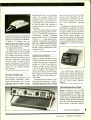
Portable Oscilloscope
OK Industries has introduced a new
do -to -10 -MHz bandwidth oscilloscope small enough to fit in most
briefcases and tool caddies. It measures only 10 "W x 7 "D x 211 "H
and adds only 2 lbs. to the carrying
weight. The compact Model 1010
provides 12 sensitivity ranges and 21
timebase ranges. Vertical sensitivity
is selectable from 10 mV/division to
50 volts /division, and timebase is
variable from 0.1 µs /division to 0.5
s /division.
The mini-scope includes internal
and external triggering with sensitivity of < 1 volt /division internal and 1
volt /division external. Coupling
modes include: ac, dc, TV frame and
TV line. A + / slope selector is also
included. Waveforms are displayed
in a 1 " x 1.5 " area on the face of the
blue-white CRT in a five horizontal
by four vertical graticule division
format. A built -in calibration circuit
is included. $355.
-
CIRCLE NO.
149 ON FREE
tone is heard when you have made
contact. Once frequencies are programmed into the scanner, the keyboard can be locked to prevent anyone from accidentally changing
them.
In addition to scanning as many as
20 channels, the scanner can search
through an entire band for an active
frequency. When a call is received,
the frequency of the broadcast appears in the numeric display. You
then have the option of continuing to
search or storing the new frequency
in one of the 20 channels. Search increments of 5, 12.5 and 25 kHz are
available.
INFORMATION CARI)
Sophisticated Scanner
Regency's Model MX7000 is one of
the few programmable fixed /mobile
scanners that can cover frequencies
as high as 1.3 GHZ. It provides continuous coverage between 800 and
1.3 GHz, as well as the usual 25 to 550
MHz. In addition, the scanner can
also monitor vhf and uhf TV audio,
FM broadcasts between 88 and 108
MHz and all civil and military aircraft bands.
Programming the scanner is simple. Entering frequencies is accomplished by keying in their numbers
via a calculator -style keypad. A beep
The multifunction lighted LCD
display shows channel numbers during scanning, channel and frequency
when a call is received, loss of power,
delay function status, channel lockout and search mode selection.
$699.95.
CIRCLE NO.
150 ON FREE
INFORMATION CARD
Telecommunicatons Tester
Simpson Electric's new 3 1/2-digit
DMM is specifically designed for
telecommunications servicing. The
Model 467-2T has direct -reading dB
ranges and is switchable for 600- and
900 -ohm references to accommodate
both new and old telecommunications systems. It also has a built -in
(Continued on page 62)
November 1985
/ MODERN ELECTRONICS /
11
I!llll'PRODUCT EVALUATIONS/111111IMININ
Audio
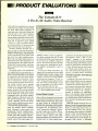
The Yamaha R -9:
A Do -It -All Audio Video Receiver
Most well -know manufacturers of stereo
components have begun to acknowledge
the much talked about integration of
audio and video. Nearly all of them have
come up with a "new" type of component: the audio /video receiver. This component might be anything from an ordinary stereo AM /FM receiver that has an
extra pair of high-level inputs labeled
"Video" or "VCR," to a multi- functional unit that includes a TV tuner and video
signal switching and section facilities.
Yamaha's elegantly designed R -9 receiver is closer to the latter description,
though it does not go so far as to incorporate a TV -band tuner. The Model R -9
is able to handle and switch signals from
any one of two video program sources.
Both video and audio signals (mono or
stereo) from such video components can
be handled and the video signals can then
be directed to a video monitor, which can
also be connected to this central Yamaha
component.
As an audio receiver, the Yamaha R -9
is as sophisticated as any audio -only receiver we've tested. Many of the unique
and thoroughly valid features introduced
by Yamaha in some of its earlier designs
have been carried over into this A/V unit,
such as continuously variable loudness
control (separate and apart from the regular volume control), and a separate
"Record Out" selector that permits you
to listen to one program while recording
another. Rated at 125 watts per channel
over the entire audio range, with less than
0.015% THD when connected to 8 -ohm
loudspeaker loads, the receiver employs
digital frequency synthesized tuning for
AM and FM listening and a 16- station
"preset" capability. It is also one of only
a few currently available receivers that includes a wireless remote control.
In terms of circuit innovations, the Yamaha R -9 designers haven't skimped,
either. Catering to those purists who
maintain that "Class A" amplifier operation still yields "purer" sound that even
the best "Class AB" amplifiers can deliver, the R -9 has a switch which, when depressed, converts the output stages of its
12
/
MODERN ELECTRONICS
/ November
amplifier section to Class A operation.
For signals requiring less than 20 watts
per channel (and that's most music most
of the time), the amplifier remains in
Class A. For those occasional brief peaks
that require more instantaneous power,
the amplifier automatically reverts to
Class AB.
As for tuner design innovations, the
Yamaha R -9 incorporates a circuit called
"Computer Servo Lock" tuning. This
provision samples incoming signals and
"decides" which of two tuning methods
will provide best reception. "Local" or
"DX" setting can be manually selected as
well, and tuning, though digital, can be
done in increments of as little as 0.01
MHz for FM and 1 kHz for AM.
The receiver measures 17% "W x 16'/,'D
x 5% "H and suggested price is $799.
Front -Panel Layout
Many of the less -frequently-used controls
and switches of this elaborate receiver are
hidden behind a hinged door flap so that
the panel retains an uncluttered look.
Controls that are always visible include
the Power on /off pushbutton, eight preset buttons that, in combination with a
"shift" button and a "Memory" button,
are used to select up to 16 AM or FM stations (in any combination), six major
function selector buttons (with additional sub-selectors for choosing AM or
FM and Video 1 or Video 2 inputs), man-
1985
ual selectors for choosing receiving mode
(for choosing "Local," "DX" or "Automatic" reception of the preferred
mode), tuning mode (automatic scanning
or manual tuning), audio Muting, a pushbutton for selecting the Automatic Class
A /Class AB mode and the dual concentric Volume and Loudness rotary controls. The continuously variable loudness
control
Yamaha feature introduced
more than six years ago -has a range of a
full 40 dB as opposed to the 20 -dB range
on earlier versions.
In addition to the usual AM or FM frequency digital displays and a ten -segment
signal "quality" display, there are specific readouts for selected tuning mode, currently selected receiving mode, status of
the preset keys (whether the "unshifted"
-a
1 through 8 numbers or the "shifted" 9
through 16 numbers are applicable),
status of the Dynamic Noise Cancelling
circuit, and of the Simulated Stereo Circuit. Small indicator lights are illiminated
above whichever program selector button
is activated.
Behind the hinged flap along the lower
section of the R -9 front panel are a headphone jack, three speaker -selector pushbuttons. a tone bypass switch, bass, treble and midrange rotary tone controls
with detented center positions, a balance
control, a DNC switch (Dynamic Noise
Control, which acts very much like dynamic filtering of the more familiar single -ended DNR circuit), a Simulated
close -by strong stations. Using the "Local" setting, best S/N in mono was 78 dB,
while in stereo it was 74 dB. These are
better -than -average figures for receiver
tuners. Harmonic distortion at strong signal levels was a remarkably low 0.06% for
mono and a nearly as low figure of 0.075%
in stereo. Usable sensitivity measured 12
dBf, improving somewhat to 10.8 dBf
when we switched to the "DX" position.
Fifty dB quieting sensitivity measured
exactly 14.5 dBf in mono, which is superb, and 37.0 dBf in stereo, which is
about average. Both are close enough to
Yamaha's published figures. When the
receiver was switched to the "DX" or
narrow i -f mode in mono, we measured
0.42% THD at all signal levels above
about 40 dBf, while stereo THD rose to
switches, but if that is done only the
speakers connected to the "Speakers A"
terminals will have their voice coils directly across the output stages of the amplifier. Those speakers connected to "Speakers B" and "Speakers C" terminals will
be operated in series, so as to maintain a
reasonably high net impedance across the
output terminals or the power amplifiers.
With only the "Speakers A" and "Speakers B" switches depressed, normal operation (both sets of speakers in parallel
across the output terminals) is maintained.
Stereo on /off switch, a Stereo /Mono
switch, the Record Out selector switch
and a switch for selecting MC (moving coil) or MM (moving- magnet) cartridge
preamplification when the main Phono
selector pushbutton is depressed.
The hand -held wireless remote control,
while not able to perform all of the control functions found on the front panel itself, is able to handle program selection,
power on /off, selection of any one of the
16 preset AM or FM stations, audio muting and volume adjustment.
If you wanted to use this receiver as an
audio /video home entertainment control
center, you might connect all of the following components to it: a pair of video
cassette recorders (VCRs), one of which
could just as easily be a videodisc player,
a TV monitor (it must be equipped with a
video input jack; connection via the antenna input will not do), a compact disc
player, a turntable equipped with either a
moving-magnet or a moving -coil cartridge, a compact disc player, two audio
tape decks and three sets of loudspeakers.
As many as three sets of speakers can
be connected and activated simultaneously by the front panel speaker selector
Tuner Measurements
In testing the FM tuner section of the R -9
receiver we quickly established that the
major difference between the "Local"
and "DX" tuning modes was not so
much a difference in sensitivity as a difference in selectivity. In other words, during FM reception the "Local" setting on
this receiver corresponds primarily to the
"Wide i-f Bandwidth" setting often
found on other tuners and receivers,
whereas the "DX" setting provides a
around 1.0 %.
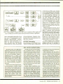
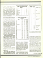
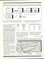
Mode of tuning ( "DX" vs "Local ")
had a great effect upon FM stereo separation, as you can see by looking at Figs. lA
and 1B. Both of these frequency sweeps
were made for strong -signal conditions
and covered the range from 20 Hz to 20
kHz in a logarithmic sweep. The two
curves in each case represent undesired
output from the unmodulated left or
higher alternate- channel selectivity figure
for zeroing in on weaker stations that
might otherwise be interfered with by
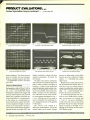
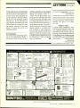
Fig. I. Separation characteristics for the Model R-9's stereo FM tunersection shown in
the local mode in curve (A) and DX mode in curve (B).
(B)
(A)
CS
CS
-10
-10
- 20'
v - 20
- 30
- 40
- 50
- 60
á - 30
O
w
>
Tv'
- 40
-50
-IP
20
100
20
10K
1K
Frequency (Hz)
Frequency (Hz)
10dB/D
L- 49.2dB
R- 57.7dB
10K
1K
100
1.00kHz
10dB/D
L-33.2dB
November 1985
/
R-40.1dB
1.00kHz
MODERN ELECTRONICS
/
13
PRODUCT EVALUATIONS...
Yamaha R -9 continued .. .
right channel, (when the opposite channel is fully modulated). In the "Local"
mode (Fig. 1A) separation at mid-frequencies ranged from 49.2 to 57.7 dB,
which is more than adequate, while in the
narrow -band or "DX" mode (Fig. 1B) it
was still adequate, ranging between 33.2
dB and 40.1 dB, depending upon which
channel was measured.
Deviation from flat response for the
fully modulated channel was never greater than 0.3 dB in the "Local" mode and
was down 1.5 dB at 15 kHz in "DX ".
We measured an excellent capture ratio
of 1.1 dB in the "Local" mode, while in
the DX mode, capture ratio increased to
2.5 dB (as claimed by Yamaha). Both i -f
and spurious response rejection measured 90 dB, while AM rejection was 57
dB and alternate- channel selectivity measured in the DX mode was 87 dB, the latter a bit higher even than the 85 dB
claimed by the manufacturer.
AM frequency response is plotted in
Fig. 2 and extended from around 50 Hz to
just over 3.0 kHz; not very impressive for
the -6 -dB points. Best signal -to -noise in
AM measured precisely 50 dB as claimed,
while harmonic distortion, at 30% moduFig. 2. Frequency response
lation, measured 0.35% for a 1 kHz modulating signal.
continuous power level of 125 watts per
channel. This means that for short bursts
of signal such as might be produced by actual music programming, the R -9 can deliver in excess of 200 watts per channel
without significant clipping!
Phono input sensitivity for a -watt
output was 0.23 millivolts for the MM
(moving- magnet) phono input option
and 15 µV for the MC (moving-coil) option. 15 millivolts of input signal applied
to any of the high -level inputs produced
watt of output. Phono overload measured 145 mV for the MM cartridge option, or 14 millivolts for the MC prepreamplifier input. Frequency response for
the high -level inputs was flat within 1 dB
from 20 Hz to 50 kHz. Yamaha has incorporated a non -switchable subsonic filter
with a nominal cutoff point of 10 Hz,
which accounts for the dropoff at the extreme low end. At the bass extreme, the
-3 dB point was reached at 12 Hz. High frequency cutoff (the -3 -dB point) occurred at 100 kHz. The range of the three
sets of tone controls is shown in the multiple -sweep plots of Figs. 3A and 3B (for
the bass and treble action) and Fig. 4 (for
the midrange tone control action).
Amplifier Measurements
In the "Auto -Class A" mode, the power
amplifier section of the R -9 remained in
Class A until output power into 8 -ohm
loads exceeded 20 watts, at which point it
smoothly switched to the more efficient
Class AB operation. Maximum output
for rated THD was 144 watts per channel
into 8 -ohm loads for most of the audio
spectrum, decreasing to 136 watts per
channel at 20 Hz and 139 watts per channel at 20 kHz. In fact, at rated output of
125 watts per channel, THD at mid -frequencies was only 0.0028 %, while at 20
Hz and 20 kHz the THD measured only
0.009% and 0.007 %, respectively. The
125 -watt per channel rating of this receiver is, therefore, a very conservative one.
Damping factor of the power amplifier
was 80, referred to 8 ohms, using a standard 50-Hz test signal. Dynamic headroom, or the ability of the amplifier to
produce short-term power peaks in excess
of its continuous power rating, was very
high, measuring 2.3 dB above the rated
of AM tuner section of R -9 receiver.
1
1
Fig. 3. Boost /cut range
FR
FR
+10
......-"'
f
0
..----'-'
-10
20
100
1K
20
10K
100
1K
10dB/D
/
3.10kHz
L- 6.1dB
MODERN ELECTRONICS
/
November 1985
10K
Frequency (Hz)
Frequency (Hz)
14
of bass (A) and treble (B) controls.
(A)
10dB/D
L-
(B)
10dB/D
L-10.4dB
8.
0dB
R+
7.
2dB
R+ 9.9dB
100Hz
10.0kHz
Signal -to -noise ratio for the MM phono inputs was 82 dB, A- weighted, referred to a 5 -mV input signal and a 1 -watt
output level. Any reading above 80 dB
would be considered a very good S/N ratio even if this were a separate high -priced
preamplifier. The MC phono input did
almost as well, with a measured S/N of 76
dB referred to a 0.5 -mV input and 1 -watt
of output. This figure, too, is excellent
and compares favorably with the figures
obtained for the high -quality separate
preamplifiers having MC head ends. Signal -to -noise for all of the high -level inputs measured 83 dB referred to 1 -watt
output and 0.5 -volt input.
In terms of rated output, these figures
are such that if a 2.0-volt maximum signal
were fed to the high -level inputs (typical
of CD player outputs) and the volume
control setting were increased to produce
125 watts, the effective S/N would be 116
dB. Since that amount of dynamic range
is well above that provided by compact
discs or other digital program sources, it
is apparent that this receiver is not going
to impose any limitations on the dynamic
range or signal -to -noise ratio achieved by
even these new program sources.
Fig. 4. Curves show range
tuners costing nearly as much as this entire receiver. What's more, the Local /DX
automatic feature worked flawlessly, always providing optimum FM reception
for a given set of incoming signal conditions. We logged more than 63 usable signals in our test location, using a good outdoor, rotatable, directional antenna. The
tuner section rarely switched into the
"DX" mode in our listening location, so
we were able to take advantage of the extremely low distortion and the excellent
stereo separation afforded by this tuner's
wideband "Local" mode.
We hooked up a good video monitor to
the appropriate terminals on the back of
the R-9 along with a video camcorder and
a VCR. Dubbing from the camcorder to
the VCR was simple, and all the while we
were able to monitor what was happening
on the connected monitor.
The R -9 served as an excellent "switchboard" or control center for every imaginable type of audio or video program
source. When we played my most dynamic CDs through the R -9, its amplifier section never ran out of power -even while
driving my low- efficiency reference
speaker systems.
(Continued on page 20)
RIAA equalization was accurate to
within 0.4 dB from 30 Hz to 20 kHz. At
20 Hz, response was off by 1.0 dB, but
that can be attributed to the presence of
the subsonic filter which is in-circuit at all
times. Figure 5 shows the action of the
separate continuously variable loudness
control at its maximum, flat position (upper curve) and at its minimum setting
which attenuates mid -frequency levels by
around 40 dB, regardless of where the
"reference" level has been set by the separate master volume control.
This dual control arrangement allows
you to set up the volume control for listening levels such as might be heard at a
live performance. Then, the Loudness
control is used to lower loudness levels to
loudness levels suitable for a home listening room. Adjusting loudness contours in
this way results in more accurate loudness
compensation than could be accomplished with the typical "Loudness
Switch" used with the volume controls on
most other receivers and amplifiers.
-
Summary
The tuner section of this receiver is at least
equal in performance to that of separate
of receiver's midrange
tone control.
Fig. 5. Curves show action
of the
variable loudness control.
FR
FR
iy
+10
0
o
=
10
-
r
10
20
30
40
20
100
10K
1K
20
100
Frequency (Hz)
Frequency (Hz)
10dB/D
L+11.8dB
R-13.1dB
10K
1K
100kHz
10dB/D
L-24.9dB
November 1985
/
R+ 5 3dB
1.00kHz
MODERN ELECTRONICS
/
15
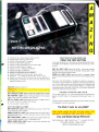
NR! Trains You At Home-As You Build
GET THE KNOW-HOW
TO REPAIR EVERY
COMPUTER ON THIS
PAGE... AND MORE.
IBM is a Registered Trademark of International Business Machine Corporation.
Epson is
a
Registered Trademark of Epson America, Inc.
Apple and the Apple logo are Registered Trademarks of Apple Computer, Inc.
Compaq Is
a
Corporation.
Registered Trademark of COMPAQ Computer
1984 AT&T Technologies, Inc.
..
4.1****
41111V-
Your Own ¡BM-Compatible Computer
Learn the Basics the NRI
Way -and Earn Good
Money Troubleshooting
Any Brand of Computer
The biggest growth in jobs
between now and 1995,
according to Department of
Labor estimates, will occur in
the computer service and
repair business, where
demand for trained technicians will actually double.
You can cash in on this
opportunity- either as a full time corporate technician or
an independent service person-once you've learned
all the basics of computers the
NRI way. NRI's practical
combination of "reason -why"
theory and "hands -on"
building skills starts you with
the fundamentals of
electronics, then guides you
through advanced electronic
circuitry and on into computer
electronics. You also learn to
program in BASIC and
machine language, the
essential languages for
troubleshooting and repair.
You Build -and Keep -a 16.
bit Sanyo personal computer
The vital core of your training
is the step -by-step building of
the 16-bit Sanyo MBC-550
series computer. Once you've
mastered the details of this
state-of-the-art machine, you'll
be qualified to service and
repair virtually every major
brand of computer, plus many
popular peripheral and
accessory devices.
With NRI training, you
learn at your own convenience,
in your own home. You set the
pace -without classroom
pressures, rigid night-school
schedules, or wasted time. You
build the Sanyo IBM compatible
computer from the keyboard
up, with your own personal
NRI instructor and the cornplete NRI technical staff ready
to answer your questions or
give you guidance and special
help whenever you need it.
Learn MS/DOS
Operating System
Praised by critics as the
"most intriguing" of all the
IBM -PC compatible cornputers, the new Sanyo uses the
same 8088 microprocessor as
the IBM-PC and features the
MS /DOS operating system. As
a result, you'll have a choice of
thousands of off-the-shelf
software programs to run on
your completed Sanyo.
Your NRI course includes
installation and troubleshooting of the "intelligent"
keyboard, power supply, and
disk drive, plus you'll check
out the 8088 microprocessor
functions, using machine
language. You'll also prepare
the interfaces for future
peripherals such as printers
and joysticks.
Your NRI course
includes the Sanyo
16 -bit IBM compatible
computer with 128K RAM, monitor, double
density /doable sided disk drive, and
"intelligen-" keyboard; the NRI Discovery
Lab °, teaching circuit design and operations;
a Digital Multimeter, Bundled Spread Sheet
and Word !0rocessing Software worth over
$1000 at retail -and more.
100Page Free Catalog
Tells More
Send the postage -paid reply
card today for NRI's big 100 page color catalog on NRI's
electronics training, which
gives you all the facts about
NRI courses in Microcomputers, Robotics, Data
Communications, TV/Video/
Audio Servicing, and other
growing high-tech career
fields. If the reply card is missing, write to the address below.
MKC
McGraw -Hill Continuing
Education Center
3939 Wisconsin Avenue, NW
Washington, DC 20016
We'll Give You Tomorrow.
00 LS
I
H
r'NA
PRODUCT EVALUATIONS...
Yamaha R -9 continued .. (from page 15)
.
The stereo synthesizer circuit, like
many others of its type, utilizes a comb filter circuit to convert a monophonic signal into a simulated stereo signal. Of
course, the resulting effect is not "true
stereo," but the spread of sound is pleasing nevertheless.
The DNC or Dynamic Noise Canceler
circuit worked in a manner very similar to
that of the DNR (Dynamic Noise Reduction) circuit, which is sold in the form of
an IC and used by many car stereo manufacturers, as well as by tape deck and
videodisc player manufacturers, among
others. DNC is a sliding low -pass filter
that follows the upper frequency limit of
program content and removes noise
above the frequency.
The three tone controls provided just
about all of the tonal compensation facilities anyone would ever need. For those
who feel that a narrower -band multicontrol equalizer is needed, the Yamaha
R -9 even has an accessory output loop to
which an equalizer or other signal processor can be connected, effectively putting the new accessory in series with the
signals passing through the receiver.
The R-9 is, without a doubt, one of the
most flexible and well thought out multifunction audio components we have encountered. Foresighted audio and video
enthusiasts may find that they may not
use all of the extensive facilities of the R-9
at first. As they become more involved in
audio and video in the future, it is very
likely that more and more of those rear
panel jacks will be filled up with audio
and video connectors. -Len Feldman.
CIRCLE 52 ON FREE INFORMATION CARD
Test Equipment
Global Specialities Scope Multiplexer:
8 inputs for 2- channel scopes
Working on much of the current array of
electronic products and systems can tax
the capabilities of most general-purpose
2- channel oscilliscopes. Products such as
computers in the digital area and video
and audio equipment in the analog area
require simultaneous display of multiple
waveforms. Using a scope with just two
input channels can be a serious handicap
when servicing them. On the other hand,
a scope with four or eight input channels
may be well beyond some budgets. However, if you already have a 2-channel
scope with at least a 20 -MHz bandwidth,
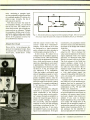
Global Specialties' Model 8001 Scope
Multiplexer is a relatively low-cost solution to the dilemma.
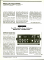
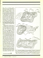
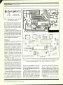
A sophisticated takeoff on the traditional multichannel switcher used in bygone days, the Model 8001 takes the basic
concept a bit beyond what has been available in the marketplace. It has eight inputs and the usual controls and outputs
provided by other "multiplexers." To
these it adds some fancy circuitry that lets
you select the number of channels you
wish to be displayed. For example it can
20
/ MODERN ELECTRONICS / November
OISPLAY
SELECT
f'f1111111,.
r11TlIllTJ
TRIG LEVEL
á
ÿi
1-4
SS
Elk
be set up to display a single waveform or,
with the flip of a switch, four or eight
waveforms simultaneously. Furthermore, an incrementing circuit whose
function is activated with the touch of a
switch lets you step through all input
channels individually for examination of
a single waveform at a time.
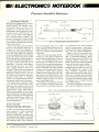
Multichannel signal processing, phase-
1985
locked loop (PLL) operation, TV tuning
and sync displays, and slower A/D and
D/A converters can all the analyzed within the Model 8001's 10-MHz trigger, 20MHz bandwidth, and 1 -MHz sampling
limitations. With the instrument's 20MHz bandwidth limitation, though, it is
restricted to use on relatively low -fre-
(Continued on page 78)
01
ATA 141=i;iI_r r_1 klieg!
CIRCLE READER SERVICE NO. FOR FREE COPY
THIS MONTH'S SPECIALS
4116
4164
4164
16K
1.39
84K 150ns
1.19
64K 200ns
5.49
258K 1SOns
AU.
EPROMS
NEW
The micro
soldering station
that's temperature
adjustable
CURRENT
4
2708 1K
2764 8K 8 300ns 64K 3 899PRN
27128 181( 300ns 128K 5.99
27256 32K x 8 25 Ons 256K 11.89 INSTRUMENTS
N
27512 64K x 8 250ns 512K 53.99
MOTOROLA
compact station is adjustable
between 500° and 700 °F
perfect production tool for
micro circuits and fine
manufacturing
grounded tip; 3 -wire
grounded power cord
includes 1 /2 -oz.
iron, tip, sponge
x
PRODUCTODUCTIOS
x
6264
8K x 8
1
Advanced Micro Dermes 1
8.99
Sona 6 4K
FULL LINE OF MICROPROCESSORS AVAILABLE
WE ALSO 3TOCac. -Breadboard & Accessories
Books
Capacitors Chemicals Connectors
Fans
Plugs & Jacks
Crystals
Heat
Fuses
Filters
Enclosures
Kits
Heat Sinks
Shrink Tubing
and stand
replacement tips
available in a wide
range of sizes,
styles and materials
Peripherals Probes Opto
Potentiometers
Knobs
PCB Products
USA
CANADA
Active
P.O. BOX 9100
WESTBOROUGH, MASS
1- 800 -343 -0874
5651 FERRIER $T.
MONTREAL QUEBEC
1- 800 -361 -5884
ISOÇTIP
7470
SELF SERVE STORES LOCATED NEAR YOU. JUST CALL...
WESTBOROUGH, MASS.
OTTAWA, ONT.
EDMONTON, ALTA.
728 -7900
438 -5888
BELLEVUE, WASH.
TORONTO, ONT.
CALGARY, ALTA.
977 -7692
235 -5300
DOWNSVIEW, ONT.
VANCOUVER, B.C.
366 -9684
L
881 -8191
MONTREAL, QUEBEC
731-7441/256 -7538
WAHL CLIPPER CORPORATION
Sterling, IL 61081
438-3321
630-0400
CIRCLE NO.
/j5-/
ICR0
15 Pin Header 8 Mating Socket,
Vert MT/PC
156" Centers
5 /1.00
50
Crystal Clock Oscillator
50
Miniature Speaker, 2 ", 8 OHM
Coils For Radio Elec's Feb. 84 N
Project, Toko a'S T -1, T-2, L -1 (/ 2uH)
8 L-2 (.071 uH) Complete Set Of All
4 Coils
8 50
MCI330- Prone (Moto)
BFQ-85 Transistor
Disc Caps .001 uf. _..
.2/100
-.
.
1.50
_. 20/1.00
74123- Prime ¡Nat. -.
470u135V(Radian..
470u116V Axlall ..
.
.3/100
..3/1.00
4/100
10/100
.
2N3904...
2N3906..
N914 ...
10/1 00
40/1.00
40/1.00
..
1
1N4148
N5231 B 5.1 V.Zener Diode))
5/1 00
7805.
Voltage Regulators (Pn me TO-220)
7812.7824,7905,7512 -Mix or Match-3/1.00
Mica Insulators For TO-220 Pkg. _20/100
Voltage Reg's (Unmarked, 60% Prime) May
Include Posdrve/Ne9 &Adjust
.15/1.00
78L08 Voltage Reg(DM1O6.TO-92I.20/1.00
....
PN2222A
.....
20/1.00
1
.
.
2N5308
2N3055
Cent
7403
7404
7410
7437
7438
7440
20/1 00
.
15) Per IC TTL
74126
7442
7450
74151
7474
74163
7476
74365
74393
7495
74107
15 Cent (.15) Per IC 74LSXX
74LS158
74LS32
74LS02
74LS257
74LS74
74LS08
74LS257
74LS86
74LS10
74L$273
74LS153
74LS20
20 Cent (.20) Per IC CMOs
4001 B. 4011B. 4050B
10/1.00
MC838 (DTL)
40
Optolsolator(H11G2 -6PIN DIP) Specs
1.45
2716 Eprom
1.95
..
2732 Eprom ....
245
2764 Eprom
4 95
27128 EPROM
256K Dram SOns Prime Hitachi (Ideal For
Mac UD rades&Expansion Prolectsl... 4.95
2 95
8243 (I/O
g Expander IC) W /Specs
.85
UDN 6118 (Uisptay Driver IC- Specs)
95
...'.. ". ..
UDN 6128
(
.
.
.
.
.
............
.
1
.
11CN4/ 168-Osc/Freq Dry Clock IC-Specs-5/1
UCN 4801 (8 Chan BrMos Latch/Driven -1 00
..45
LM339
.45
LM3801 ULN22801
4/1.00
555 Timers (TI)
50
NE556 (Dual Timer-Moto)...
741JOpAmpIMini Dip Hi Rel Pkgl .4/1.00
LM1310 (Unmarked. Tested Prime) ...50
.
.
(201)
654.6006
`fer
45
LM3900
AM /FM Radio IC (a2204 W/Specs -Hobby)
-
15/100
IC Sockets
8 PIN / .07
14 PIN / .13
16 PIN / .15
18 PIN/ .17
20 PIN / .19
22 PIN / .21
24 PIN/ .22
28 PIN/ .24
40 PIN/ .39
7 Segment Displayl.3` CommonCath) ..
15
7 Segment Display(.6" Common Ann)
..65
Tn State LED's
..
..3/1.00
Jumbo Red LED's -Diffused Lens, Prime (T11.
All 100% Prime-15/51,100/56.1,000/557.50
15/1.00
LED Mounting Clips Rings
Texas InstJ *994A Keyboard- Inc/Data For
Pins MadeWhen Each Key Depressed. 495
..
Dip Switch-12 Position...
2/100
4/1.00
Dip Switch -8 Position.
Keyboard Push Button Tops
30/1.00
Audio Cable
.. .. 30 Feet /100
22AWG Wire...
50 Feet /1 00
27AWG Wire
.. .... 50 Feet /1.00
-
-
-
-
.
.
Mini Lubricator
Lubricant)
.1.00
Molex Pers17 PhVStnp1100 /$2,500/$4,1K/56
Clock Module-Crystal Controlled. Green
Display /12VDC/Time Set Switches/Data-495
Rotary Switch (5 Position, 5A 125V)- 3/1.00
Giant Alpha Numeric Display 1 -1/2" X 2"
7x5135 TotalI Red LED Matrix/Specs -4 -95
11 LED Bar Graph Display-2-3/4". Rect
LED's(SpecifvRed,Grn,Ambl Specs .. -2.69
Seven Amp( 71 Tapped Transformer-Gan Be
Wired For(25 9V. 15V. 18V) Reg Shpg .. 8.95
Wall Plu Transformer- 24V 525mA.. .1.50
ente Transformer
20
Center Tap Transformer
2.50
Mie, Audio Transformers.
10/1.00
1N4007
20/1.00
15/100
N5059 (200V Amp)
10/100
1N5060 400V Amp
Zener Diodes -20V 1W
30/1.00
Zener Diodes-13V 1W Glass.
30/1 00
Crystal
50
.50
3.579545 Color Burst Crystal II-IC-181
3.579545
1.0 Mhz Crystal ..
1.95
.1.95
6.0 Mhz Crystal
...
TO-5 Heat Sinks (Bern)
10/1 00
TO-18 Heat Sinks t Bern)..
- .. 10/1.00
Super Sub-Mini Ceramic Caps (All 100V)
... 30/1 00
.0015uí 100V (152)
... 30/100
00225f 100V 182...
..30/1.00
00275f 100V 272...
30/1.00
.0033uí 100V 3321
.. 30 /1.00
0039uí 100V (3921.
.0056uí 100V)562)
.30/1.00
30/1.00
.0082uí 1ó0V 8221)
4.7uí 40V Lytic Radial)
20/1 00
10/1.00
47uf 25V Lytic (Radial)
1000uí 185V Twist Lock ...
1.00
3200uí 50V (Ideal For Power Supplies)-1.00
56000 25V (Comp Grade 3-5 /8X1)- 3/1.00
10/1.00
.1ut 50V Monolithic&
20/1.00
.22u1 50V Monolitnics
(&
-
1
122
ON FREE INFORMATION CARD
74SC374 -D Type Flip-Flop. NoNlnv
74SC533-D Type Flip- lop, Nln /Inv
74SC534 -D Type Flip -Flop. Inverted
745C540-Octal Buffer/Line Driver -Inv
74SC541 -Octal Buffer/Line Driver -N /I
74SC563-Octal arent Latch Inverted
74SC564 -D Type Fhp-Flop. Inverted
745C573-Transparent Latch. Non /Inv
74SC574-D Type Flip -Flop, Non /Inv
8á.3p1 -1.00
10/1.00
.3351 apps -Dip
1,000PC Resistor Asst (30 Values) 1/2W -$3
Pots -1 Meg. Linear Taper
5 /1.00
Motion Detector Bds (Inc IC -$2)
7/10.00
Mot Det (IC On ULN2no IC -5/$2- 20/10.00
Project Box/Li For Detector
195
Miniature Speaker For Detector
25
Extensive Construction Article For Det. $1
Chip Caps-Set of
508 Central Aye.
WNNiNQ N.J. 07090
MART
(815) 625 -6525
2902 Locust Street
1
1
-
.
.
.
.
.
-
.
2 Each 2.7
4, 2
N Knobs
15/1.00
Ammeter (0-15 A.C. Amperes)
4.95
Volt/OHM Meter MVMNT 10-1K OHM,
0-300V)
.. 2.95
6V Miniature Gear Molor.
..
50
RFChokes- 1.Buh, 8.2uh, 12uh, 22 5 5- 0/100
.50
22/44 Pin Edge Card Connector
75
34 Pin Connector(For Drives) W /Hood
.95
BNC "T' Connector(UG274)
Mixed Connector Asst
10/1.00
1.5AMP 50V Bridge (GI, TO-5 Pkg)
.50
25AMP20OVBndge(Solder Lug Term)
1.50
Zenith TV Replacement IC Special BI Each
221 -42, 221 -43, 221 -45, 221 -48, 221 -69,
221 -78,221- 87,221- 96,221 -104,221 -105.
221- 106, 221 -140
2SD900 (Horiz Output W /Damper Diode)-2.95
2$C1172B (Toshib -Horn Output Trans) -1.95
Winegard4 Bay Bowtie UHF Antenna -19.50
IC Storage (Bug) Box (Holds) 30 IC's-1.75
Data Book For All Above
(ulti -Tum) Trim
50
1
Pay TV Hardware Installation Kit Blow Out
As low MS2.95 + $3.50 Shipping Per Unit
All Kits Contain 5 F Connectors. 300 to 75
OHM Balun. 3000HM Terminal Block 2 Ft
J50HM Patch Cord 2 Ft 300 OHM Twin Lead.
Pots (Copal)
Nylon Cable Ties And UHF Antenna
Model *4124$2.95 Includes All Of
The Above Plus 25 Feet Coaxial Cable And
Mounting Hardware For Indoor WalIrCeihng
Installation
Model *4880-S2.95 Includes All Of
The Above Plus 25 Feet Coaxial Cable And
Attractive Expandable Pole /U-Bolt For
Easy Indoor Installation
Model *484543.95 Includes All Of
The Above Plus 65 Feet Coaxial Cable And
All Necessary U -Bolt Hardware
RMrPF10VHorMt(SingleTum)Tdmmers
100 OHM, 1K. 10K, 25K. 50K, 100K _. 4/$1
Heat Sensitive Switch /150' C
10/1.00
10 /1.00
Mixed Coil Asst
Buzzers
3/1.00
20/1.00
Chip Resistor (6.8K)
20/1.00
Chip Resistor (470K) .........
20/1.00
Chip Cap 1330p1)
Jumbo Red LED W /Buds In Resistor -30/$1
MRF901 IHobbyGrade-60%Good... 10/1.00
IC Asst( Hobby Grade, Some Marked)-30/51
.
MODEL 705
20 Cent (.20) 74SCXX
Series Special
a Vdtag.
AC Voltage
DC Carrent
AC Curant
H14ó Resistance
e
'
74SC137 -t Of 8 Inverted Decoder. Latched
74SC138 -1 018 Inverted Decoder
74SC139-1 Of 4 Inverted Decoder
74$C237 -1 Of 8 Non -Inverted. Latched
74SC238 -1 Of 8 Non -Inverted
74SC239-1 014 Non -Inverted
748C240 -Octal Buffer /Line Driver -Inv
74SC241 -Octal Buffer /Line Driver-N /I
74SC244 Octal Buller /Line Driver-N /I
745C245-Octal Bus Transceiver -NOD'1
745C373- Transparent Latch- Non/Inv
Talk
2
Control Basic Interpreter Ore-Chip
Auto-Start Operation At Power-On
Fast 16 -Bd Multiply And Divide
RS-232. Supports CRT & Serial Link
24 Bi- Directional I/O Lures I8255AI
RAM Memory-2K Expandable To t 6K
Eprom Memory-Expandable To 16K
Built In Eprom Programmer
ParrlCentronix) Printer Interface
Optional Real -Time Clock W /Backup
100 OHM. 500 OHM, iK, 2K 5K 10K. 20K
50K 1001( 200K, 500K, 1M-.85 Each-3 /S2
Octal Interface Circuits
Equivalent To 74LSXX Series
Low Power ISO-CMOS Technology
Short Propagation Delay
Improved Noise Margins
High Current, Sink/Source Capability
.
4(NATMHz.NS8073)
8-Bit Microprocessor
1
Preclalon
I's.
Cypher IV Micro-Controller Kit- $129.50
.
Diode resat
Mrr ie,i
Digital Multimeter
tooi.v to t000v
taary to rwv
0..44 to IDA
0.1VA Is 10A
alb
to
lee to
$51
95
2171A0
2OCF
Iavn1.1 voltage toting
vanerstor tssung
UHF -TV PREAMP
featured m Radio Electronics March/
May articles, 1982)
(As
This inexpensive antenna mounted pre
amp can add more than 25 dB of gain to
your system. Lots of satisfied Customers
and repeat orders for this high quality kit.
which includes all component parts. PC
BO, Case. Power Supply and Balun ß4.S0
f57.5ó
Assembled Version..
-
MICRO -MART accepts Visa MC and tektphone CODs. Minimum order $10.00
Shipping-
Os orders. $2.00 Canada and other cotxttres $3.50 (includes ins.). Shipping rate adjusted where
applicable NJ residents add 6% sales lax
500 CENTRAL AVE.. ESTFIELD, NJ 07000
(!0110544011
MICRO -MART
CIRCLE 58 ON FREE INFORMATION CARD
November 1985
/
MODERN ELECTRONICS
/
21
Radar Detectors
A guide to automobile radar detection equipment
and methods
By Ron Cogan
you're moving along at a moderate pace in your car one evening, barely nudging the posted speed limit of 40 mph while traversing from Florida's east coast toward
Tampa and the Gulf of Mexico.
22
/
MODERN ELECTRONICS
/
Suddenly, the sharp beams of
headlights pierce the darkness from
behind, and the late evening calm explodes in an array of brilliant red
lights reflected in your rear -view mirror. Your presence is being requested
at the shoulder of the road by the local constabulary.
November 1985
What did you do, you wonder? After a moment of discussion, you learn
that you passed through a town that
cut into the main road for about '/
mile and that a new speed limit of 25
mph was supposedly marked for this
somewhere.
short stretch
It was all past discussion because
...
November 1985
The slim K40 Remote radar detector comes with a guarantee against cost
radar speeding tickets for the first
you were caught in the innocent act
of one of the greatest revenue- generating devices ever devised for city and
state governments- police radar!
Many small towns purposefully set
up this way to enhance their operating budget. Unknowing drivers sufunless they have a radar
fer for it
detector to defind against entrapment.
...
What
Is Police
Radar?
The word "radar" is a simple acronym for "RAdio Detecting And
Ranging." We're all aware that this
of
18 months.
The Spectrum Whistler remote detector with a weatherproof front end
that's mounted behind a car's grille.
Cincinnati Microwave's popular Escort, which uses surface mounted device (SMD) construction.
system is used to aid and track the
navigation of aircraft everywhere.
Some years ago, an innovative soul
came up with an interesting applica-
Band" at 21.150 GHz, to augment
the existing radar program. This narrower frequency was better suited for
shorter-range applications.
The evolution of police radar units
over the years has been an interesting
one. Early police radar units were
rather simplistic, high -power devices
which were capable of pinpointing
vehicle speed at about a half-mile
range. These were physically mounted to the patrol vehicle and used from
a stationary position. This was followed by police radar used in moving
as well as stationary vehicles, and
these moving patrol cars were cap-
tion of radar to combat speeding motorists on the highway. A single radar
unit in a strategic location began to
be used to pinpoint speeding vehicles. The F.C.C. initially allocated
what is known as the "X Band" at a
frequency of 10.525 GHz to be used
for police radar enforcement. The
long wavelength of this band made it
perfect for monitoring highways and
interstates. After a time, the F.C.C.
allocated a second frequency, the "K
November 1985
/
MODERN ELECTRONICS /
23
Fox Marketing 's XKMR model is designed for use with motorcycles, featuring
very small size, weatherproofing, and high shock-resistance.
able of aiming radar to the front and
the rear for maximum coverage.
Then the police radar arsenal expanded to include low- power, instant-on, pulse, and radar hand-gun
units. Radar speed enforcement was
here to stay.
While there is certainly some merit
to the use of speed radar, it has unfortunately gained a rather soiled reputation because it has been abused.
What was initially introduced as an
innovative and futuristic method of
enforcing traffic speed limits became
the high -tech answer to methodically
building city coffers.
Countless police agencies foregoed
placing their radar-equipped patrol
cars in plain view, where their high
profile would graphically alert motorists that they should maintain a legal speed. Instead, the police units
often "hide" by stationing themselves between parked cars, just over
the crest of a hill, and around corners
where they could surprise their four wheeled prey and be guaranteed of
writing an iron -clad ticket. Thus,
"speed traps" became a popular
road game.
But many motorists grew weary of
losing and decided to become active
players in this game. Concurrently,
several innovative companies devised
products that they believed would aid
the harried motorist in his quest to
24
/
MODERN ELECTRONICS
/
Dynascan's
Cobra
Trapshooter
RD-41000.
drive ticket -free without fear of being nailed by major -league electronics. This new and exciting product
became known as the "radar detector," of course.
An Exciting
"Defensive Weapon"
With the introductionof the radar detector came a new way to battle the
invisible and effective microwaves of
police radar. It could sense the high power, continuous emissions of
X -Band radar well in advance of its
effective range, even over hills and
around corners. Thus, a driver could
be afforded plenty of warning that he
had best be traveling the posted speed
limit for the coming miles until the
radar trap was passed.
As is the case with any new technological wonder, the first generation
November 1985
of radar detectors did their job in a
most basic way. They usually did detect the presence of police radar when
it was being used, and in fact did save
countless motorists from speeding
tickets (and some likely accidents)
because they were forewarned. But
they would have to improve, because
the next salvo in the radar war was
fired by the other side, and it was
substantial enough to make counting
on immunity through radar detection
a risky endeavor.
This salvo was actually a two pronged attack. First, a number of
states decided that this activity went
against the grain of a society intent
upon enforcing its laws, so they took
the legal approach. In essence, such
states banned the use of radar detectors, making such use a ticketable offense. In the case of a few states that
took an even more hard -line approach, a motorist caught with a radar detector could be arrested,
hauled off to jail, and have his detector confiscated.
rti1
..._.
.gs..
Uniden's Bandit 55.
Radio Shack's Road Patrol XK.
However, under Title 47 of the
Communications Act of 1934, the
Federal Communications Commission specifically states that no radio
receiver can be licensed, restricted, or
banned. Since a radar detector is indeed a radio receiver, this caused the
legality of the blanket banning of
radar detectors to come into question. After the dust cleared on this
legal matter, only two states -Virginia and Connecticut -have chosen
to maintain that radar detectors are
illegal through rather creative interpretations of the law.
The second part of the two pronged attack involved police agencies receiving approval for the new
K -Band frequency. They began employing these units in conjunction
with, and sometimes in lieu of, the
first -generation X Band radar devices.
As the radar war heated up and a
new generation of radar detectors
were unleashed to detect the presence
of both X and K band police radar,
the offense took further technological steps to make detection more difficult than ever before. Entering the
picture at this critical point was the
low -power speed radar device to preclude long -range detection, and the
pulse radar, which would send inter mittant signals in an attempt to
thwart easy detection by the present
genre of radar detectors on the
market.
The counter to this was production
of more sensitive detection systems
to match the offensive capabilities of
the newest police radar devices. They
would be infinitely more sensitive to
the presence of elusive police microwaves in order to warn of a speed
radar trap in time.
Enhanced sensitivity in general
does increase the odds of ferreting
out the more difficult -to- detect police radar signals, but it does not
come without cost. Ultra- sensitive
detectors all- too -often experience an
unnerving problem that radar detector manufacturers are still trying to
engineer out of their units
today -false- triggering.
False- triggering is simply your
radar detector warning you of the
presence of police radar when, actually, none exists. Unfortunately,
other devices also operate on the very
same frequencies used by police
radar. Among these offenders are
microwave security systems, phone
relay stations, and garage-door
openers. Some radar detectors also
leak signals that can trigger a radar
warning on other detectors.
An answer provided by a number
of radar detector manufacturers was
to build in simple controls that would
enable a driver to reduce X -band
Electroalert's Superhet XK.
detector sensitivity in urban areas,
where such signals are more likely to
be found.
The city /highway switch found on
some radar detectors does the desensitizing job automatically and attempts to find a median where both
tasks can be accommodated as best as
possible. As a rule of thumb, if a
radar detector warning does occur in
the city, there is no way you can really
determine if it has been triggered by
police radar or a spurious signal. The
best bet here is to simply slow down
to prevent even the possibility of getting a ticket.
Detector Designs
The first radar detectors introduced
on the market were typically bulky
and designed to reside on a vehicle's
dashboard via either a heavy magnet
or a solid mount. After a time, technical innovations resulted in lighter,
more compact units that could also
be installed with clips or Velcro tape.
Smallish units are now available
that can be clipped to a sun visor, and
November 1985
/
MODERN ELECTRONICS / 25
Radar Detector Buying Guide
Deciding which radar detector to buy is
probably more challenging than purchasing most other popular electronic
equipment. Unfortunately, there are no
real standards upon which to weigh one
product against another. No specifications for comparison purposes.
The keys to making a buying decision
might be broken down into the following: price, one -piece or remote, size,
features, company reputation, plus any
information you can gather from retail
sales people and radar -detector users.
You can pick up a basic radar detector for as little as $60, but don't expect it to have the best sensitivity or selectivity, not to mention anti false-triggering circuits, city/highway switching,
and other attractive features. The top
detectors are pushing $300 ( "list ") and
some exceed this price, less discount.
Remote units are the most costly in any
maker's line. Here are some representative suggested retail prices of detectors
on the market:
BEL- Tronics' "MicroEye 841" $190
Cincinnati Microwave's
Regency's "RS Five"
$149
Uniden's "Bandit 55"
$190
You pay more for really compact units,
which use the latest microminiaturization
techniques. They offer the benefit of taking up less space in an automobile and can
be easily removed and stowed away to
avoid the prying eyes of thieves. The control heads of remotes are exquisitely
small. For example, Cincinnati Microwave's "Passport" remote ($295) measures only 3/4 "H x 4 % "W x 23/4 'D.
Then you should decide how the radar
detector should be installed. Would you
like to have one with a visor -clip mounting, a permanent under-dash location, a
top -of -dash temporary mounting. Do
you want to plug the power line into your
cigar lighter or have a fixed -power connection? What you wish will determine in
part the type of unit you'll buy. Keep in
mind, too, that some people are wary of
doing their own permanent- installation
work, required for remotes and for fixed
hookup to the car's battery supply.
There'll be an installation charge for a
professional to do this, of course.
When you come to features, the latest
top -of -line detectors have anti- false-triggering circuits, aural and visual indicators, city /highway switching, volume
controls, mute switch, automatic brightness control, system test to verify that the
detector is indeed working, and external
speaker jack, among other features.
Even among features there are sub categories. For instance, what type of signal strength indicator is incorporated into the
detector to let you know about the
strength of the radar transmission being
picked up? Is it an audio beeper, flash frequency, LED indicator, meter, or combination of a few? Is there a different
sound made to distinguish between an
Radar detectors respond to different
radar signals in various ways. Whichever
model you get, you'll have to familiarize
yourself with its warnings. One model
might start beeping slowly, increasing as
you approach the signal source, beep for
several seconds and stop under another
condition, emit raspy sounds for a few
seconds in yet another condition,letc.
How well does the detector respond on
each band under different practical conditions: Over -the-hill, Smokey at your
back or front door, around a curve, in a
large urban area, and so on. Furthermore, how good is the detector's shielding against local oscillator radiation from
other detectors being carried in nearby
cars. You'll have to ask a lot of questions
to possibly learn the answers.
Keep in mind, too, that radar detectors
are not foolproof. For example, an instant-on radar fired at you closeby will
catch you even though your detector responds. You won't have time to slow
down in this case. Furthermore,
VASCAR (visual average speed computer and recorder), among other non radar devices, will not be detected by a
radar detector, naturally. Moreover, this
method is dependent on a person starting
a timer and is, therefore, inaccurate.
Insofar as company reputation is concerned, this information would have to be
ferreted out. Some companies bend over
backwards to please purchasers. Others
virtually ignore you should you have a
problem out of warranty and even in warranty.
one manufacturer has even designed
a detector with a contoured housing
that allows it to fit between the forward part of a dashboard and the
windshield glass so it will be as inconspicuous as possible.
Along with the proliferation of visor -mount detectors we're seeing on
the market, the remote -type radar
detector has also realized a substantial following. These units typically
utilize a weatherproof radar detector
that is mounted behind any plastic
grille or other non -metallic part at the
front of a vehicle, and a tiny hardwired remote control head that can
be mounted inconspicuously inside
the car.
Popularity of remote -type radar
detectors grows as more people
realize that some states and towns do
not recognize the legality of using
one, and theft of radar detectors has
risen sharply, along with car radio cassette systems.
Packing this sophisticated elec-
tronics package into such smallish
housings as side mirrors and tiny
visor -mount packages (some small
enough to fit in a briefcase or pocket)
is, of course, due in no small part to
the use of integrated circuits and
microprocessors. It is also partially
due to innovative antenna designs
which have grown much more effective, yet smaller, over the years.
Among the types of antenna used by
the latest radar detectors are the horn
antenna, multibeam printed circuit
"Escort"
$245
Controlonics' "Whistler
Spectrum"
Dynascan's "Cobra RD- 4100"
Electrolert's "Fuzzbuster XK"
Fox' "XKMR" (Motorcycle)
K-40's "Remote"
Radio Shack's
"Road Patrol XK"
26
/
MODERN ELECTRONICS
.
$300*
$200
$160
$200
$340*
$180
/
November 1985
X -band and K -band signal being picked
up?
An important distinction is that
when a suspect signal is received, it
processes and analyzes the incoming
signals to determine if they are being
generated by radar or by a source
other than radar. This "electronic
fingerprinting" prevents the unit
from false-triggering from most
other -than -radar sources.
Some of the new radar detectors
take a different approach. Instead of
discounting all spurious signals,
these units presume that a driver
should be made aware of a suspect
signal even if the detector is not convinced it is being generated by police
11111V4ii
VMS
GUL Industries' Model 83S.
radar.
As an example, Controlonics,
among others, has built a new filter
mode into its detectors that can be
switched on when driving into an urban area. Instead of reducing the sensitivity of the radar detector (and
thereby affecting optimum ability to
monitor for police radar), the unit
(Continued on page 83)
Regency's Super Long Range XK.
antenna, and a hybrid combining a
half-horn and microstrip antenna.
Although many radar detectors
are designed to be permanently wired
into a vehicle's electrical system,
others still use the same cigar -lighter
plugs (or offer these as options)
which were used on most of the early
radar detectors. These are particularly handy for drivers who may want to
transfer their radar detector from
one family vehicle to another, and
also for those who want to regularly
remove their unit from the car to prevent the possibility of theft when it is
parked.
The latest generation of radar detectors incorporate sophisticated
superheterodyne circuitry. Unlike
their passive first -generation cousins, which simply determine that microwave signals were present in an
area and then signaled a warning,
these new devices take a more active
role in protection againt police radar.
RADAR-DETECTOR MANUFACTURERS
BEL-Tronics Limited
3031 West Pawnee
Wichita, KS
(Brand Name: Micro Eye Selectra)
Cincinnati Microwave
One Microwave Plaza
Cincinnati, OH 45296
(Brand Names: Escort, Passport)
Controlonics Corp.
Five Lyberty Way
Westford, MA 01886
(Brand Name: Whistler)
Electrolert, Inc.
4949 South 25A
Tipp City, OH 45371
(Brand Name: Fuzzbuster)
Dynascan Corp.
6460 West Cortland St.
Chicago, IL 60635
(Brand Name: Cobra Trapshooter)
Fox Marketing
4518 Taylorsville Rd.
Dayton, OH 45424
(Brand Names: Roadstar, Matchbox,
SuperFox)
GUL Industries
23978 Craftsman Rd.
Calabasas, CA 91302
K40 Electronics
1500 Executive Dr.
Elgin, IL 60120
Radio Shack
300 One Tandy Center
Fort Worth, TX 76102
(Brand Name: Road Patrol)
Regency Electronics, Inc.
7707 Records St.
Indianapolis, IN 46226
Uniden Corp. of America
6345 Castleway Ct.
Indianapolis, IN 46250
(Brand Name: Bandit)
November 1985
/
MODERN ELECTRONICS
/
27
Satellite TV
RCA Goes Ku -Band
New satellites to serve TV broadcasting, business
and home TVRO viewers
By Stan Prentiss
all systems go! RCA is
ready to rocket two satellites into Ku-band orbit
late this year and expects both to become operational in early 1986.
Ground support will consist of excellent ColorTrak 2000 TV receivers
with compatible NTSC transmission
systems and LinkabitTM scrambling.
In a consolidated effort by RCA
Americom, RCA Astro- Electronics,
RCA Laboratories and RCA Consumer Products, the massive undertaking will begin with the launch of
12/24 -GHz broadcast and syndication satellite K -2 aboard the new
Space Shuttle Atlantis this November. Then in December, Space Shut -.
tle Columbia will set into orbit cable
and business satellite K -1. Both satellites are scheduled to become operational by February 1986. (A third satellite, K -3 is slated to fly in 1988.)
A preview of the new satellite system was given to selected industry and
technical press people at the David
Sarnoff Research Center in Princeton, NJ, earlier this year by staff vice president B. J. Lechner and others.
Announcements and demonstrations
also included introduction of
B -NTSC, an augmented video /audio
TV system designed to compete with
Britain's B-MAC now being marketed in the U.S. by Scientific Atlanta.
With
28
/
MODERN ELECTRONICS / November
B -NTSC is wholly compatible with
current TV broadcasting and receivers for standard transmission, and its
signals can easily be scrambled and
decoded by sets that could have external or internal decoders available in
1986. Later, as additional engineering is further refined and compacted
into large -scale integration (LSI) circuits, RCA digital television will join
the parade of advanced video /audio
developments, bringing even greater
flexibility to televised picture and
sound processing, along with digital
1985
receiver controls and special effects
not now available in ordinary analog
receivers.
As digital systems are advanced,
removal of most, if not all, artifacts
(stray video) and cross -color (color
interference) should be eliminated
with whole frame store instead of today's line of signal additive and subtractive comb filter luma -chroma
separation. Furthermore, as techniques are mastered, both line and
frame averaging will result in considerably better definition and resolu-
CAMERA
nu
MATRIX
rill
1171
6
T
D/A
ELLIPTIC
FILTER
COMPRESSOR
5.5MHz
ELLIPTIC
FILTER
RISC
é
TIME
PRE-EMPHASIS
ARRAY
NTSC
A
Ill
ELLIPTIC
FILTER
EXPANDER
42
NTSC
ENCODER
MHz
ELLIPTIC
N
TSC
FILTER
RF
PRE- EMPHASIS
LINK
ARRAY
6 MHz
TDMC
MATRIX
in both line and field, space remains
for two audio channels as well as digital commands for both sync restora-
TDMC
MHz
TDMC
DE
EMPHASIS
ARRAY
o
NTSC
DE- EMPHASIS
ARRAY
RISC
R
GB
MONITOR
EiR
Fig. 1. Block diagram compares B -NTSC system readied by RCA (upper portion) with Britain's B-MAC system (lower portion) currently in operation.
tion at reasonable bandwidths. Even
now, up to 30 megasamples can be
digitized experimentally, accomodating an analog beamwidth of 15
MHz. So when all luminance has
been removed from the chroma
channel and vice -versa, you see clean
chroma- luminance frequency interleaving without contamination of either color or picture.
B-NTSC Processing
By processing a total NTSC band-
width of 4.2 MHz and stripping sync
tion and scrambling. Digitized, the
two encrypted audio channels, control data signals, and 3.58 -MHz
chroma sync reference occupy the
horizontal blanking period, in addition to an auxiliary data channel.
During the 1.3- millisecond vertical
blanking period, digital sync information is transmitted and video becomes inverted.
When the signal is received, sync is
recovered from the vertical interval,
audio is removed from horizontal
blanking and converted back to analog, video is reinverted, and regenerated sync locks a steady raster. Link abit scrambling, we are told, will
handle up to 250 channels of information and a 56 -bit program authorization word for customer access.
A block diagram that compares
Time Division Multiplex Component
(TDMC) B-MAC to B -NTSC is
shown in Fig. 1. The switch at the far
RCA's K-Series Ku -Band Satellites
Identified by RCA as the 4000 Series
spacecraft, each of the new K -Series Kuband satellites can cover part of or the
entire U.S. Additionally, there will be
one spot beam for Hawaii. Orbital assignments are at 67 °, 77 ° and 87 ° west
longitude (WL). A fourth assignment is
being held as a reserve ground spare.
Shuttle Mission 61 -B, flown by Atlantis, will loft K-2 into orbit on November
27. Then on December 20, Mission
61 -C, flown by Columbia, will place K-1
into orbit.
These two new birds will join five other lower- frequency 4 /6-GHz C-band
RCA satellites that are already providing government and commercial communications throughout the U.S. Services of the K (4000) Series will include
broadcast and syndication, master -antenna systems, direct -to -home broadcasting, and "private" voice, voice
data, and teleconferencing for business
and government.
Certainly the most powerful satellites
now in domestic service, 16 45 -watt
transponders on each satellite will be offered to participants in RCA Americorn's syndication system in a no -cost
(free) antenna /receiver package. The
only charge will be $1000 to defray installation, as long as the 3.7-meter Kuband antenna is pointed at a K -Series
satellite. Signal -to -noise ratios for a single video transponder using this equipment is specified at 55.5 dB, and 50 dB
for two over most of the country under
clear -sky conditions.
Ground station installations have
been under construction since summer,
with initial programming scheduled for
K-2 in February 1986. More than 400
standard -power commercial TV stations (out of a total of 900) have already
accepted the service. Hubbard Broadcasting's U.S. Satellite Broadcasting,
Inc. has now leased four of the K-2
transponders for more than $85-million
to distribute its news service and other
programming to affiliates.
RCA Americom says that RCA's
strong Ku -band entry occurred because
50-state C band CONUS (continental
U.S.) is "nearing orbital capacity,"
that power and siting restrictions are
less exacting at Ku frequencies, and that
there is little terrestrial microwave interference with which to contend and almost unlimited placement of receiving
antennas on the ground. Densely populated metropolitan sites are also included, as long as there is line -of -sight
access to the particular satellite.
The K Series will have dual horizontal /vertical polarization, a design life of
10 years, and transponder switching
from east to west to CONUS on ground
command. They will contain six backup
transponders for the two polarities and
will measure 63.5 feet overall. At time
of launch, each will weight 4144 pounds,
which will drop to 2170 pounds in orbit.
November 1985
/
MODERN ELECTRONICS
/
29
right serves to illustrate general
transmit and receive techniques of
each system. While there is video
compression and expansion in the
TDMC arrangement shown in the
lower portion of Fig. 2, NTSC simply
passes the composite signal through a
5.5 -MHz elliptic filter, adds the usual
video preemphasis, reverses the process during receive, and feeds the results into a line comb/ notch filter
monitor or receiver. The TDMC system must convert all its compressed
information back to analog via an
A/D converter, expand and matrix
the color difference for RGB, then either supply an RGB monitor directly
or go through an NTSC decode process and then feed a standard NTSC
receiver.
Although RCA concedes MAC allows slightly more overdeviation and
a bit more impulse noise, engineers
believe that MAC has poorer luminance S /N. NTSC uses standard
CCIR video preemphasis, rather
than MAC's fixed 3 dB. The two audio systems, Dolby delta modulation
and pulse code modulation, are different, but both begin to fail at carrier -to -noise (C /N) ratios of 6 to 7 dB.
In a consumer product, RCA
claims that hard video scrambling is
impractical and unnecessary, but
audio scrambling becomes essential,
along with secure encryption control
of coded signals and subscriber turn
on and turn off keys. Though MAC
eliminates both cross -color and cross luminance from NTSC, it also requires linear RGB inputs into any TV
receiver (few receivers have this capability). Later, of course, the NTSC
system will eliminate two problems
with frame -comb decoders, and progressive scan will remove any occasional flicker or line crawl. Motion adaptive progressive scan and frame comb filters will physically supplant
the single -line comb filters used to-
(Continued on page 84)
30
,
/ MODERN ELECTRONICS / November
of diagrams illustrates reception `footprints" possible with
-band
K Series satellites. Top diagram shows eastern U.S. covthe new RCA Ku
western
U.S. coverage and bottom diagram CONUS coverage, center diagram
at a nominal 77° west longitude assignment.
K
-2
in
orbit
are
with
erage. All
Fig. 2. This series
1985
EXPAND YOUR CAREER HORIZONS...
itossimmailimemak
-
--.y
.s.-s..
t--AMMMIiW,IIM
i----_iki...
_.._
1CMINIM-AMENIMIIIMONI
id.IMIIMONIAMMOMMINIMMMW
®=RigeMi
111111MW
-
t
The CIE Microprocessor Trainer helps you to learn how circuits with
microprocessors function in computers.
START WITH CIE.
Microprocessor Technology. Satellite Comm nications.
Robotics. Wherever you want to go in electronics
... start first with CIE.
Why CIE? Because we're the leader ii teaching
electronics through independent study. ConsEider this.
We teach over 25,000 students from all over the
United States and in over 70 foreign counties. And
we've been doing it for over 50 years, help ng
thousands of men and women get started n
electronics careers.
We offer flexible training to meet your needs.
You can start at the beginner evel or, if ycu already
know something about electronics, you may want to
start at a higher level. Bat wherever you st-t, you
can go as far as you like. You can even earn your
Associate in Applied Science Degree in Electronics.
Let us get you started today. Just call toll -free
1-800-361-2155 (in Ohio, 1-800 -362 -2105) or mail in
CIRCLE
5
ON FREE INFORMATION CARD
the handy reply coupon or card below to:
C eveland Institute cf Electronics,
1 776 East 17th Street, Cleveland, Ohio 44114.
r
CIE
MO-44
Cleveland Institute of Electronics
1776 East 17th St., Cleveland, Ohio 44114
LI Please send your free independent study catalog.
For your convenience, CIE will try to have a representative
there is no obligation.
con:act you
-
Point Name
Apt.
Addrass
Cty
Age
State
Zip
Area Code /Phone No
Check box for G.I. Bill bulletin on Educational Benefits
Active Duty
Veteran
MAIL TODAY!
Books
The Siliconnection
A new book by Forrest Mims examines the
silicon -connected modern age of electronics
through his personal involvement in it.
By Art Salsberg
Microelectronic life is largely
based on a raw material
called silicon, the second
most abundant element in the earth's
crust. Using special refining methods, this semiconducting material
has changed the face of electronics
due to its low cost and miniature size.
Starting with the development of a
transfer resistor at Bell Laboratories,
called a "transistor," and evolving
to an integrated circuit in the late
1950s, it has revolutionized our lives
through a host of affordable consumer electronics products, from
digital watches to computers.
Silicon's impact on society is so
strong that an area of the U.S. where
many semiconductor developers
gathered is called "Silicon Valley," a
term applied only 15 years ago to a
sleepy, orchard -laden area of northern California, the Santa Clara Valley. Located about 30 miles south of
San Francisco, near Stanford University, the seeds were planted by establishment of the first semiconductor company on the West Coast by
transistor co- developer William
Shockley. The year was 1955, only 30
years ago. High -technology compatriots followed quickly, and the area
became a glamour -spot for silicon based companies.
Forrest Mims, in his new book,
"Siliconnection," published by the
McGraw -Hill Book Company, is a
personalized coming-of- silicon-age
story, starting with his first awaken-
34
/
MODERN ELECTRONICS
/
H. Edward Roberts reviews a MITS calculator schematic in 1974, a few months
prior to designing the Altair computer.
Forrest Mims preparing to launch a radiocontrolled rocket near Saigon, 1967.
(U.S. Air Force photo.)
(Photo by Forrest M. Mims III.)
ing upon seeing a photograph of a
transistor in 1954.
He details his extraordinary experiences related to the silicon technology through three decades of exciting involvement with it. Given his
wide- ranging brushes with the world
of silicon, he might well have titled
his book, "Siliconescapades."
In this book, for example, he relates how he met Ed Roberts and
joined business forces with him; the
origins of their company, MITS,
which later introduced the Altair
8800 computer that spearheaded the
personal computer revolution in
1975; and how they split up (amicably with a payout of about $950 in
cash and kind. (Six years later the
company shares would be worth
$15,000!)
His work at the Air Force Weapons
November 1985
Lab is detailed, from the Silicon Zoo
to Laser Reflections. His "Confessions of a High -Tech Spy" includes
his experiences in building laser
"bugging" apparatus, his involvement with the National Inquirer,
which expressed interest in Forrest
using his electronic equipment to flyby Howard Hughes' abode to capture the man's utterings.
Of special historical interest are his
details on William Shockley leaving
Bell Labs to return to his hometown,
Palo Alto, in California, to establish
the Shockley Semiconductor Laboratory in nearby Mountain View, and
how key people left to form Fairchild
Semiconductor, whose defecting engineers and physicians left, in turn, to
turn silicon into gold with such compaaies as Intel.
Forrest's inside information on
_may
Rï.e'rti6lEslj
ant
«
ePJr
zt
T
a
<<. ps P
,r`
VezE nc e
E i rs+r<
c
E,-,ç-DEO
ü
AT
r,84:
4
.
FFCn
PReHr,p
M
6é(JReSï
AvüO
zcc,
F
777
T
323
r,y
tor
tor
C64-t
..trtrv+wJ¿
Tilg ESrAW
p...01 c-,1g _F
f4 010r
A
page from one of fForrest Mims' notebooks that led to his series of hand-let-
tened books published by n'adio Shack.
(Photo by Forrest M. Miims Ill.)
how the BASIC language was developed for commerical use through the
association of Bill Gates with Ed
Roberts, the former finally setting up
his own company, Microsoft (which
later developed the defacto standard
operating system for 16 -bit computers, MS -DOS) is especially intriguing. So was his discussions of the
early software pirates
Dr. Uta Merzbach, a curator at Smithsonian Institution's National Museum of
American History and Forrest M. Mims
reviewing early MITS papers that Mims
will donate to the Smithsonian.
.
(Photo by Minnie C. Mims.)
His chapters on "Silicon Law"
and "Mims Versus Bell Labs" can
serve readers well in understanding
how tough it is for a little guy to go up
against a giant corporation when trying to assert his rights to a development. The inventer of FM radio, Edwin Armstrong, must have suffered
extreme anguish during his legal pursuits against RCA, finally committing suicide. Forrest, too, was exasperated, but wrote about his experience instead, which included
house searches that stunned him, and
other unwelcome actions he reveals. I
recall giving a deposition in the Bell
Labs case during this period, which
concerned fiber-optic communications. Read it and weep!
The author delves deeply into the
world of computers, of course, discussing his first -hand experiences
with people who were pioneers in the
computer industry, including startup
of the Radio Shack computers and
his secretive introduction to the
TRS-80 Model I computer in a Texas
warehouse.
In all, Siliconnections is an enthralling inside look at an industry
founded on silicon, and how Forrest
Mims interacted with it on his
journey as an independent electronics /computer journalist, experimenter, and inventor.
The book is highly recommended
to anyone interested in what makes
an important part of this amazing
high -tech industry tick, as well as
reading
interesting
providing
through the author's sprightly writings about his personal involvement
with a host of people who contributed to the growth of silicon-based
equipment. Eight pages of photographs complement the text.
116
Siliconnections by Forrest M. Mims III.
Published by McGraw -Hill Book Cornpany, New York, NY. 240 pp., hard
cover, $16.95. (Expected publishing
date: November 1985.)
November 1985
/
MODERN ELECTRONICS /
35
Project
Mello- Phone: The Super
Musical Telephone Ringer
Build-it-yourself project substitutes up to 200
selectable musical tunes of extended length for a
standard telephone ringer
By Steve Lympany
It occurred to me one day, while
calming my nerves following a
startling blast from my phone's
bell ringer, that there must be a pleasant yet effective way of signalling an
incoming telephone call. Electronic
music being one of my hobbies, I decided what I wanted was a telephone
ringer that plays music, and thus was
born the "Mello- Phone."
While there are commercial products that substitute an electronic music box for the normal telephone ringer, these are generally limited to just a
few notes from a fixed set of tunes
chosen by the manufacturer. I wanted to select the tunes to suit my personal tastes and be able to listen to
more than seven or eight notes for
each tune, as with the Mello-Phone.
The Mello -Phone can play up to 200
different selections of varying
lengths of up to 252 notes and rests. I
use selections such as college fight
songs, seasonal tunes, and a few Mozart and Beethoven pieces. The
choices, of course, are unlimited.
The Mello -Phone installs between
your telephone set and your telephone wall outlet using standard
RJ 11 C telephone connectors. It requires external power from a commonly available 9 -volt dc adapter. It
won't interfere with normal tele-
36
/
MODERN ELECTRONICS
/ November
phone operation, and it can be used
with rotary or Touch -ToneTM dialers.
When someone calls, the Mello Phone automatically disables the bell
in your telephone and replaces it with
a musical tune that plays repeatedly
until you answer the phone or the
caller terminates the call. In the latter
case, the Mello -Phone will play the
current tune through to completion
and then stop automatically.
Circuit Description
As shown in Fig. 1, the Mello -Phone
uses only four ICs. Here, UI and U2
are opto-isolators, U3 is the music
1985
synthesizer and U4 is an EPROM for
storing the music. The music synthesizer is a General Instruments ÁY -31350 microprocessor.
Operation of the Mello -Phone is as
follows. Firstly, Pl plugs into the telephone outlet and your telephone
plugs into JI. Now, when a 20 -Hz
ring signal of 40 to 150 volts is present
at the tip and ring leads (green and
red leads of PI), current flows
through RI 7, C6, D6through D9, DI
and opto- isolator U2. The current
through pins 1 and 2 of U2 causes pin
5 to go low to signal a start -tune request from the synthesizer via Q2.
Diodes D2 through D5 form a
<
A
m
A
Ó
<
m
n
r
f
D
r0
f
';'c
I
v
A
O
I
'
m
2
rn
m
cn
<
o
rThis is the overall schematic of the Mello -Phone musical ringer.
It is powered by a 9 -volt dc adapter, regulated to + 5 volts dc by the circuit. Tune selections are made with DIP switch SI.
Fig.
1.
I
-----
O
t
November 1985
/
MODERN ELECTRONICS / 37
"Plays tune until phone is answered or song over."
can replace R19 with a 100,000 -ohm
PARTS LIST
Semiconductors
D1- 1N4758A zener diode
D2 thru D5,D10-1 N4004 rectifier diode
D6 thru D9,D11- 1N4148 diode
Q1- 2N2222A npn transistor
Q2-2N2907A pnp transistor
Q3,Q4- TIP120 Darlington transistor
U1,U2 -4N25 opto- isolator
U3 -AY -3 -1350 music synthesizer
(General Instruments)
U4 -2732A EPROM (programmed;
see Notes below)
Capacitors
Cl,C2,C5- 10-µF, 25 -volt electrolytic
C3-240 -pF disc
C4 -1 -µF electrolytic
C6-0.47 -µF, 250-volt metallized Mylar
C7,C8-0.1 -µF disc
C9-0.22 -µF disc
Resistors (1/4-watt, 10 %)
R1 -120 ohms
R2- 680,000 ohms
R3 -6800 ohms
R4-270,000 ohms
R5 , R6, R7, R 14, R 15, R 16, R21- 100,000
ohms
bridge circuit that allows only a dc
signal to flow through the telephone
during incoming ringing. This effectively disables the normal bell or
chirp ringer in your telephone, since
they require ac to operate. Zener diode DI prevents stray current surges,
such as those that result from other
pulse -dialing telephones on your
line, from triggering a tune.
Mello -Phone will play the selected
tune until the telephone is answered
or until the song is over. While the
song is playing, subsequent ringing
bursts will not reset the tune. When
the tune ends, the next ring burst will
restart it, beginning a new cycle.
When the telephone is answered,
dc flows through bridge circuit D2
through D5, UI, and out to the telephone via the red and green leads of
JI. The current through pins 1 and 2
of Ul pulls pin 5 low, resetting the
synthesizer and stopping the tune.
Answering the phone resets the pro-
38
/
MODERN ELECTRONICS
/
R8,R9,R13- 33,000 ohms
RIO,R19,R20 -4700 ohms
R1 1,R12-10,000 ohms
R17 -3300 ohms
R18- 10,000 -ohm upright pc -mount
trimmer potentiometer
Miscellaneous
J1 -RJ11 (6- position) telephone jack
P1- Telephone line cord
S1- 4-position DIP switch
S2 -Dpdt slide switch
SPKR- Miniature (2') 8 -ohm speaker
Printed -circuit board; 9 -volt dc, 150- to
200-mA adapter; IC sockets; suitable
enclosure; spacers; hookup wire; solder; etc.
Note: The following are available from Steve
Lympany, Clavier Electronics, Inc., P.O.
Box 51281, Raleigh, NC 27609: etched and
drilled pc board for $6.95; AY -3 -1350 for
$5.50; preprogrammed 2732A EPROM
for $7.50; Ri 11 (6- position) telephone
jack for $2.25; 4N25 opto- isolator for
$1.50 each; complete kit of parts, including speaker, 9 -volt adapter and enclosure,
for $43.00. Include $1.00 P &H.
cessor so that the next time a ring signal comes in, the tune will start at the
beginning. Resistor R1 prevents the
ring signal and other minor surges
from triggering the off-hook circuit.
In the audio section of the Mello
Phone, envelope control is accomplished with U3 pin 13. When no tune
is playing, pin 13 remains low, keeping C5 discharged. This allows R 19 to
pull the base of Q3 low, keeping it
off. When a note is being played, the
note frequency appears at U3 pin 14.
Pin 13 goes to a high- impedance state
and allows RIO to charge C5 to 9 volts
dc. This turns on Q3 and places 9
volts dc on the emitter of Q3. Pin 14
toggles Q4 to produce the desired
pitch at the speaker. At the end of the
note duration, pin 14 continues to
toggle at the previous note frequency. However, pin 13 goes low, allowing C5 to discharge through R19.
This results in a decaying sound upon
turn off of each note. If desired, you
November 1985
-
potentiometer to permit adjusting
for various decay envelopes.
Other than the address and data
lines between the synthesizer and
EPROM U4, the rest of the Mello Phone circuitry involves adjustments
and song selection switching.
Speaker volume is adjusted by
R21, which varies the drive level to
Q4. Tempo resistor R2 sets the speed
at which the synthesizer steps through
the notes. If you prefer to be able to
vary the tempo, you can replace R2
with a 1.2- megohm potentiometer.
The indicated fixed 680,000 -ohm resistor provides a quarter note duration of approximately 250 milliseconds. Absolute pitch of the notes can
be adjusted by varying the oscillator
frequency at pin 27 by changing the
value of R3. If you wish, you can replace R3 with a 10,000 -ohm potentiometer. (The fixed 5699 -ohm resistor
results in a middle C frequency of
about 185 Hz, which is low by about
six semitones.)
Switches SIA through SID are used
to select which of the 16 tunes is to be
played. These switches set the status
of the upper four address bits of the
U4 EPROM. Thus, the switches can
select one of 16 "pages" of memory
in U4, each page containing 256
bytes. (Up to 25 selections can be programmed per page, but more complicated circuitry involving sharing the
synthesizer address bus for tune selection is required. There are also 28
tunes programmed into the synthesizer that can be accessed. Interested
readers can contact me, per the address in the Parts List, or refer to the
General Instruments data sheets for
information on these features).
As designed, the Mello -Phone
dedicates one page of memory per
tune. This simplifies the tune- selection circuitry and permits longer
tunes, containing up to 252 notes and
rests, to be played. A 2716 EPROM
can be substituted as long as SID is
set to OFF at all times. Thus, eight
tunes can be selected using switches
SIA, SIB and SIC.
Power for the circuit is derived
from the ac line via a 9 -volt adapter
feeding VR1, Cl and C2. The incoming 9 volts is regulated down to the
5 -volt dc level required by the remainder of the circuitry. A standard
9 -volt, 150 - to 200 -mA adapter is sufficient for powering the Mello Phone. Maximum power consumption of about 1 watt occurs when the
phone is ringing and speaker volume
is turned up to maximum.
Table 1. Note Duration Table
NAME
Semiquaver
OCTAL
BINARY
0
000
ADDRESS
DATA
0
377
(tune select timeslot)
001
Quaver
Dotted Quaver
2
010
Crochet
3
011
4
100
5
101
6
110
7
111
Dotted Croche t
..
Minim
Dotted Minim
J.
Semibreve
Tune
1
(tune -end marker)
377
Tune 2
Table 2. Note Pitch Table
Programming the Synthesizer
During this discussion, memory locations and data will be referenced in
octal, with hexadecimal notation in
parentheses. The music to be played
by the AY -3 -1350 is stored in 2732A
EPROM memory in the form of 8 -bit
data bytes. Each memory byte describes the pitch and the duration of
the note being played.
The lower three bits specify note
duration, the upper five bits the
pitch. This permits 32 different
pitches and eight different duration
values to be specified. One pitch code
is allocated as "silent" to allow musical rests of differing lengths to be implemented. Table 1 gives duration
data, while Table 2 gives the pitch
data for use in programming.
When programming the EPROM,
a few rules must be observed. In each
page of memory, EPROM address
000 (00) must contain data 377 (FF).
EPROM address 377 (FF) in each
page must contain data 125 (55),
which is a key to open the external
EPROM. Following the tune data,
the last two bytes should be 377 (FF)
and 376 (FE), indicating the tune end
marker and end of listing marker.
Fig. 2 is a diagram of EPROM memory allocation per page.
The first part of the "Star Spangled Banner" is shown in Fig. 3 as an
example of encoding. Below the
notes are shown the octal and hex
codes to use.
If you don't have access to an
EPROM programmer, you can obtain a preprogrammed EPROM con-
MUSICAL
NOTATION
(tune -end marker)
377
NAME
FREQUENCY
(Hz)
OCTAL
F
175
Fe
G
B
C (middle C)
CA
D
185
196
208
220
233
247
262
277
294
DN
311
E
330
349
370
392
GA
A
AM
F
FO
G
GA
A (international A)
AN
B
C
CN
D
DA
E
F
Flf
G
GA
A
AC
B
Rest
00
01
02
03
04
05
10
12
01000
01001
01010
13
01011
14
01100
01101
01110
01111
10000
10001
10010
15
16
17
440
466
494
523
554
587
622
659
698
740
784
20
831
Silent
21
22
23
Last Tune
00101
00110
415
880
932
988
00000
00001
00010
00011
00100
06
07
11
More Tunes
BINARY
00111
10011
24
25
26
27
10100
30
11000
31
11001
32
11010
33
34
35
36
37
11011
11100
11101
11110
11111
10101
10110
10111
taining 16 tunes ( "Camptown
Races," Beethoven's Ninth Symphony," "My Darlin' Clementine,"
"O Come All Ye Faithful," Brahm's
Hungarian Dance No. 5, to name just
a few) from the source given in the
Parts List. Other tunes can easily be
programmed from the sheet music;
contact the author for details.
Construction
377
t
376
000
000
000
000
i
125
377
(tune -end marker)
(end of listing)
Not Used
(external ROM
enable key)
Fig. 2. EPROM allocation map per
memory page, data column in octal.
wiring technique to assemble the circuit. Of course, the printed- circuitboard technique is the simplest, since
it offers a neat, logical component arrangement with a minimum of actual
hand wiring and minimizes the possibility of making wiring errors.
You can fabricate your own pc
board, using the actual -size etching and- drilling guide shown, or purchase a ready -to -use pc board from
the source given in the Parts List. In
either case, use the components placement diagram in Fig. 4 to guide
you in component installation. When
mounting components on the board,
make sure you properly orient the diodes and electrolytic capacitors be-
This is a relatively simple project to
build. You can use just about any
November 1985
(Continued on page 88)
/
MODERN ELECTRONICS
/
41
i
Project
A Computer System
Power Controller
(with Surge -Spike Protection)
Lets you individually turn on /off your computer
and peripherals from one central location
By Paul M. Spannbauer
you tired of reaching
around to the back of your
computer, the side of your
printer and the back of your modem
to turn each on or off? Or wonder if
you should add more surge and spike
protection devices? You can overcome these irritants by buying a
bunch of commercially available devices, of course, but at considerable
cost. My solution to this problem was
to build my own ac -line power controller with built in surge/spike suppressors. Cost was about $62, including a fancy cabinet for the project.
Everything fits inside a handsome
shielded metal box. The ac outlets into which the system equipment plug
are located on the rear panel, while
all switches and their status indicators mount on the front panel. If you
examine the photos, you can see that
my Controller was designed to have
four outlet /switch /indicator combinations to suit the needs of my
computer system, plus a master
POWER switch and panel lamp. You
can add more outlet /switch /indicator sections as needed to customize
your Controller for the needs of your
system. You can also use this device
for other electronic systems, such as
stereo and video setups, of course.
Are
42
/ MODERN ELECTRONICS / November
About The Circuit
The complete schematic diagram of
the Controller is shown in Fig. 1. The
circuit is really quite simple in design.
Note that throughout the circuit the
standard white /black /green three conductor wiring scheme is used. It is
highly recommended that you maintain this scheme exactly and do not
attempt to change it to a two- conductor system. All computer products
use this wiring scheme for ac line operation, though most consumer
video and audio products don't.
Even if you want to control power to
only two- conductor wired products,
you'll find that they are compatible
with this Controller.
Items in your system you want to
control plug into ac receptacles SO1
through SOS. (The subscript n here
and below simply indicates that you
can have four or more of each components in your Controller.) Power
1985
to these receptacles are individually
controlled by switches S2 through Sn,
while the neon lamps in 12 through
In, respectively, will light whenever
the switch in a given circuit is closed
and power is being delivered from the
ac line. You can add receptacle/
switch /lamp combinations as needed
by your system, the only limit being
the amount of power the EMI filter/
suppressor can handle.
Main power switch S1 determines
whether or not ac line power is available for switching to the individual ac
receptacles. With S1 closed this
power is available and can be selectively fed to the receptacles. With S1
open, no power is available, regardless of the status of the other switches
in the Controller.
The circuit shown in Fig. 1 is a
minimum Controller system. There
are, of course a few modifications
you can make to it to further custom-
_[
o
S01
WHT
BLK
SO
S03
SO2
WHT
BLK
WHT
BLK
BLK
WHT
GRN
WHT
WHT
WH
GRN
EMI filter/
Suppressor
BLK
BLK
K
14
13
12
S2j
/1uB\L
S4
S3
117V a.c.
PARTS LIST
sembly
S1
-Dpdt miniature toggle switch
Sñ Spst
S2 thru
miniature toggle
switch
SO-Chassis-mount, threeconductor ac receptacle
Misc. -EMI filter /suppressor module
SO1 thru
Fig.
1.
ize and enhance it. For example, in
hi -fi and video systems, there are
items you never want unpowered.
These include timers, turntables,
videocassette recorders and the like.
Therefore, you can incorporate into
your Controller one or more ac receptacles that are unswitched. Connect these directly across the ac line
where the line cord enters the Con-
--
NEUTRAL (GRN( LINE
CIRCUIT BREAKER (SEE TEXT)
WHT
TO FILTER
GRN
BLK
WHT
BLK
(A)
I
troller box, ahead of Sl (see Fig. 2A).
Another modification you might
wish to make is the addition of a circuit breaker. You can obtain pushbutton -reset circuit breakers in a
wide variety of load ratings. Determine what the maximum load would
normally be for your system and select an appropriately rated breaker.
Install the breaker in the line between
uNSWITCHED
NEEDED)
Note: You can substitute illuminated push on /push -off illuminated switches (Radio
Shack No. 275 -676) for I2 /S2 through
/SB combinations.
Overall schematic of a minimum controller system.
Fig. 2. Options that can be added to a basic controller system include series
of unswitched receptacles (A) and circuit-breaker protection (B).
RECEPTACLES
(AS MANY AS
white, black and green wire; wire nuts
(5); spade lugs (optional); rubber feet
(4); dry- transfer lettering kit; clear
acrylic spray; etc.
Corcom Model 8109 or similar); suitble metal enclosure (5%"W x 5'/4'D x
3'TI Radio Shack No. 270 -253 accommodates a four-receptacle system; adjust size accordingly for more
than this); heavy -duty, three- conductor ac line cord with plug and strain
relief; 12- or 14 -gauge stranded
thru In-Panel-mount neon -lamp as-
I1
INPUTS
the point where the ac line cord enters
the Controller box and S/ (Fig. 2B).
Putting it Together
The most difficult step in building
this project is making the cutouts in
which the receptacles mount on the
rear panel. These must be cut square
and uniform in size and location. Depending on the tools you have, there
are several ways to make these cutouts. The easiest, of course, is with a
chassis punch. Second best is to use a
nibbling tool. If neither tool is available, you're stuck with drilling holes
and working like mad with a file to
make the cutouts the proper size and
shape. Be careful to make the cutouts
just the right size.
Once you've finished making the
receptacles cutouts, drill the entry
(B)
(Continued on page 85)
November 1985
/
MODERN ELECTRONICS
/
43
Project
A Solid -State
Light Dissolver
Controller smoothly dims or brightens lights
automatically with the flip of a switch
By Imre Gorgenyi*
controllers are always
popular projects not only because they are practical projects, but also because they are fun to
use imaginatively. A good light controller, like the Solid -State Light Dissolver described here, will smoothly
dim or brighten lights with the flip of
a switch. In addition to automatic,
flicker -free fade -in or fade -out of
Lfight
lights, the Light Dissolver provides
full manual control and an instant on feature. Also, you can tailor its
circuit to suit specific needs simply by
changing the value of resistors.
As designed, the Light Dissolver
can handle up to 300 watts of lighting
(resistive, or incandescent) or a small
ac motor, such as a fan. To provide
maximum safety and assure long operating life, the project must be
housed inside a plastic -not metal
box with adequate ventilation.
-
Uses
By now, you probably have a good
idea of some of the uses to which the
Light Dissolver can be put. Here are a
representative few:
You can permanently wire a
Light Dissolver for simple fadein /out of lighting in any room.
*Motorola, Inc. Small Signal
and Sensor Products
44
/ MODERN ELECTRONICS / November
A
very practical application is to
use a Light Dissolver to slowly fade
out lights when you leave your home,
garage, workshop, etc. You will
never trip over unseen obstacles in
the dark again. For this application,
use a 2- to 5- minute fade -out.
Another application is to have
adjustable background lighting for
viewing TV, working at a computer
video terminal, or setting a "mood."
Once the desired level is manually set,
flip the switch to on and the light will
come up to the preset level.
1985
You can also use the Light Dissolver as a speed controller for a
small dc motor. The motor's speed
will come up slowly, instead of
abruptly the way it does with HIGH/
MEDIUM /LOW fan switches.
Being more imaginative, you can
use two Light Dissolvers with two
slide ç:ojectors to give really professional presentations. Connect a
Light Dissolver to each projector and
set one Dissolver for fade -out, the
other for fade-in. A 1- or 2- second
period for the fade -in and fade-out
R5
tOK
10K
1N4001
SUI
.R4
;5K
R7
D1
MANUAL
r
1.2M
R6
IDA 920
n/Ve.
ON
OF
ECT1
(see
text)
812
100
R14
4K
03
51
AUTO
LI
R13
180
1K
MPS6514
R3
150K
' 3.3K
R
01
INSTANT
ON
6
;R8
52
Ri
ICI
MOC30 0
2
04
2N4871
R9
1,;
02
220K
MPS6516
F
MTZ
4
R2.
11,
220K
s
5.6K
(add for
fast off)
C1
{R10
100"F
IuF
56K
C3
10F
R11
C2
200
J
0
2N4
6071
MTt
1
PARTS LIST
Semiconductors
D1- 1N4001 rectifier diode
IC 1- MOC3010 triac driver (Motorola)
Q1- MPS3904 or MPS6514 npn transi tor (Motorola)
Q2- MPS3906 or MPS6516 pnp transi tor (Motorola)
Q3- 2N4871 unijunction transistor
Q4-2N6071 B (200-volt, 4- ampere) or
MAC222-4 (Motorola) triac
RECT 1 -MDA -920-4 bridge rectifier
(Motorola)
Capacitors
C1- 100 -µF, 25 -volt electrolytic
C2-0.1 -µF, 50-volt disc
C3,C4-0.1 -µF, 200 -volt disc
Fig. 1. This is the overall schematic diagram of the Light
Dissolver. Note that the common lines for the ac line and
periods is best. In operation, have the
fade -in projector start its action
about midway through the fade-out
projector's period. This will momentarily superimpose the frame
from the two projectors on the screen
and eliminate the annoying blackout
on the screen between slide changes.
you have only one slide projector, you can still spice up your
presentations with a Light Dissolver.
Just have the Dissolver control a
150 -watt lamp directed at the screen
to cast a colored light between slides.
When you advance the projector, simultaneously push the instant -on
button on the Dissolver. (Use the Dis-
If
dio Shack No. 273 -102 or similar)
-Dpst slide or toggle switch
52-Normally -open, momentary -action pushbutton switch
SO1 -Ac receptacle (see text)
Resistors (1/2- or 1/4-watt, 10 %)
R1 -2.2 megohms
R2,R9-220,000 ohms
R3- 150,000 ohms
R7- 10,000 ohms
R8 -1000 ohms
R10- 56,000 ohms
Rl 1 -200 ohms
R12 -100 ohms
R13 -180 ohms
R14 -2400 ohms
R5- 10,000 ohms, 2 watts
R6 -3300 ohms, 2 watts
R4 -5000 -ohm potentiometer
Miscellaneous
L1 -Coil; two in parallel -see text (Ra-
S1
Printed-circuit board or perforated
board and push -in solder terminals;
socket for ICI (optional); heat sink
for Q4 (see text); control knob for
R4; suitable enclosure (Radio Shack
No. 270-223 or similar); " x % "
bracket; 'A" spacer; silicone heat transfer paste; ac line cord or extension cord (see text); machine hardware; hookup wire; solder; etc.
1
control circuits must be kept isolated. This task is accomplished with opto- isolating triac driver ICI.
solver's manual control to set the desired light level.)
Many other applications for the
Light Dissolver should come to
mind. We have presented here just a
few ideas to get you started.
About the Circuit
Shown in Fig. 1 is the overall schematic diagram of the Dissolver. Dimming action is controlled by varying
the amount of current passed
through triac Q4 and, thus, the lamp
plugged into ac receptacle S01. The
triac is a solid-state device that can be
triggered into conduction in both directions by a low- level, short pulse
applied to its gate (G). It can be shut
off only by removing the voltage at
main terminal 1 or main terminal 2
(MT1 or MT2). Since the ac line
voltage passes through zero (effectively removing the voltage) 120
times every second, there is no need
for a manual device, such as a switch,
to interrupt the voltage. This being
the case, we only have to add to our
circuit the elements required to turn
on the triac.
Since the voltage on the ac line
passes through zero every half cycle,
the duration of the current going
through the load at SO1 depends on
just where in the cycle Q4 is triggered
November 1985
/
MODERN ELECTRONICS
/
45
into conduction. Early triggering
produces bright light, while late triggering allows the lamp to shine less
bright. The task of triggering Q4 into
conduction at the desired point in the
cycle falls to the circuit made up of bipolar transistors QI and Q2 and unijunction transistor Q3.
Unij unction transistor Q3 operates as a relaxation oscillator whose
output pulse frequency depends on
how fast capacitor C2 recharges after
firing. Transistors Ql and Q2 furnish
the charging current, with the R3 /Cl
and RI/R2/C1 time -constant networks controlling the turn -on and
turn -off times.
You can tailor the circuit to your
specific needs in either or both of two
ways. If you want the lamp to turn on
faster, simply change the value of R3,
either by using a lower -value resistor
or by paralleling the 150,000 -ohm resistor with another resistor. Similar-
ly, if you want a faster turn -off, you
can do the same with R2.
There are two common lines in this
circuit. One is connected to the nega-'
tive (
side of rectifier assembly
RECTI and serves the control cir-
-)
cuitry. The other is connected to the
ac power line and serves as the return
path for the load current. It is essential that these lines be kept isolated
from each other. While you can use a
power or small pulse transformer to
provide isolation, an opto-coupled
triac driver, shown in Fig. 1 as ICI,
offers a neater solution.
Inside IC1 are a light- emitting
diode (LED), a detector and a small
triac. In the Fig. 1 circuit, the low level pulses coming from Q3 make
the LED in ICI emit short bursts of
light that are picked up and converted into electrical current pulses
by the internal detector. This small
current triggers the internal triac,
Fig. 2. Use the actual-size etching-and-drilling guide at the
left to fabricate a printed- circuit board for the project.
46
/
MODERN ELECTRONICS
/
November 1985
which then outputs pulses to the gate
of power triac Q4, triggering it on so
that it delivers current to the lamp.
Potentiometer R4 serves as a
master control of the pulse rate and
provides both manual control and a
limit in the brightness of the lamp
plugged into SOI. Momentarily
pressing S2 causes the lamp to instantly turn on.
Choke LI suppresses any spikes
produced by the power triac and limits interference with AM radio reception. No safeguards against interference need be made for FM and TV reception, since these media are immune to this type of noise.
Construction
This is a relatively simple circuit to
build and, thus, lends itself to just
about any wiring technique. If you
wish, you can fabricate a printed -circuit board for the project, using the
Then mount all components (except R4, SI, S2 and SOI)
exactly as detailed in the diagram shown at the right.
Fig. 3. Note in this close -up view how two chokes are wired in parallelfor LI and
the L- bracket heat sink used for Q4 (upper-left), use of a 16 pin socket for IC1
(lower-left), and single screw that mounts the board on the box (center).
actual -size etching and drilling guide
shown in Fig. 2. If you do use the pcboard approach and decide to use a
socket for ICI, be sure to drill a small
hole for pin 3 of the socket. (You will
not be able to find a six-pin socket in
any of the catalogs or electronics
parts stores. So you will either have
to use a 14- or 16 -pin socket carefully
trimmed to size or two strips of three
Molex Soldercons.) If you forego using a socket, you can simply clip off
pin 3 of ICI and eliminate the need
for an extra hole in the board.
Mount the components on the pc
board exactly as shown in the components- placement diagram in Fig.
2, making sure that the leads of the
transistors go into the proper holes
(see the detail drawings at the lower left of the components -placement
diagram). Note also the orientations
of DI, Cl and RECTI.
Choke LI consists of two 100 -µH
r -f coils. Place the two chokes side by
side and wrap a couple of turns of the
leads of one around the leads of the
other so that the chokes are in parallel. Solder the connections and clip
off the excess lengths from the
twisted leads. Then bend the unclipped leads and install the choke
pair on the board via the L 1 holes (see
Fig. 3 for mounting details).
Mount the transistor about '/a "
and the Q4 triac about % " above the
top surface of the board. Make sure
the rear (metal) face of Q4 is oriented
away from LI and parallels the long
edge of the board.
Prepare seven 6 "lengths of hookup wire by stripping 1/4 " of insulation
from each end. Plug one end of these
wires into the holes labeled R4, S1
and S2. The other ends of these wires
will be connected later.
You have two choices with regard
to the ac receptacle into which the
lamp load plugs. One is to use a chassis -mount receptacle and run lamp
cord between it and the appropriate
points on the board; the other is to
use a cut -off section of extension
cord that enters the cabinet through a
side wall (see lead photo). The latter
is easier and has the advantage of
providing you with an essentially nocost ac line cord.
Disassemble the box in which the
project is to be housed and temporarily set aside the top panel. Machine the box as follows. First, drill
three or four 1/4 " holes through the
long wall at the lower -right corner
and two more holes through the short
wall adjacent to where the first set of
holes are drilled. These serve as a vent
for heat in the area occupied by triac
Q4 when the project is assembled.
Drill the hole for the line cord
through the long wall opposite that in
which the vent holes are drilled. If
you use the latter type of receptacle
discussed above, drill a second hole
in this wall to permit its cord to enter
the box and connect to the board.
Off-the -board components R4, SI
and S2 mount on what was originally
intended as the bottom of the box.
Drill the mounting holes for these
components, locating them where
there will be no interference with the
components on the pc board. If you
have decided to use a chassis -mount
ac receptacle, machine a slot in which
it will mount on the blank short wall.
Mount the components in their various locations, and place a control
knob on R4's shaft.
Turn over the box and place the pcboard assembly alongside it and, referring back to Fig. 1, connect and
solder the free ends of the hookup
wires to the appropriate lugs on R4,
SI and S2.
If you are using the chassis -mount
ac receptacle, clip 6" from the free
end of the line cord and separate the
two conductors thus obtained. Strip
1/4 " of insulation from both ends of
both conductors. Tightly twist together the fine wires and sparingly tin
with solder. Then plug one end of
each wire into the holes on the board
labeled SO1 and solder. Connect and
solder the free ends of these wires to
the lugs of SOI. Prepare the free ends
of the conductors of the remaining
November 1985
(Continued on page 83)
/
MODERN ELECTRONICS /
47
0
¡,057
AYRA
Pocket Com II
This is T HF trans, ewer for aspr
iny James or Dick Tracys in our
community. Full 2 -way transmission and a size that fits secretly
into your pocket A great gift for
any child. Cat D-1101
oK,..0°,,%r,,%
V ! 1e°o^9éN
o
51695 /L
ta`B.
5OP\.,sw
Heom
Se^éó2
h
c° detsi° s
uHésesM1
nS
é
tOd`R`K`h,s
\,
n
ho(ó,9ot
^Ó ou\e(
(mo\d
Ce
O
o^
Ñ
; jec
W ha
:
s
O
m°"
Go\V!
p20
/JI¡'y
(¡
-
`_
`C°
d
b
bO
át
ams o\
5y
baoaJ
e
aM
o
Y
d
sG\PN
da^eM1qpst
s
s
cPa^s^O s
e EAc
A'
t
to
p 1e
o
Úi
Pmbos,A
a
c
` ^e
s
tae
tn4
t^l e
hA`aS°5
hptcy
cóN
t
s
dtdseAs
d
ós ^
O
S
A
ode VI500\ \l Aa
5`
600°`'
..
h
s v+
o`e0
d
a s
eN
sset9
oC
ne`,°
\
s
"emsaen
bd^
d\;
t
Have you priced o built up
wattmeter lately? Just re-
*
Odlai
71I
Fes...'
s1995
-
735
,,,, ..x
layouts. Level crossing
flashing unit, scale fluorescent lamps, street
signs. Devices to build.
/f
Cat B -3633
V
leased
Featuring stripline circuitry,
this kit is easy to build & use.
Specifications
DIRECTMTY:
20db
INSERTION LOSS:
. 0 3db
FREQUENCY
(narrow
RESPONSEband)
usable over
400 -520
MHz
trag. range
MAX POWER-
95
ketw"Hh
trt st(
Antep q
U5 WoMOVMpUSttO,AI`edrsL
hOmpW`W^`
owaaó
edHpe
oser
be°use
rcn^ °ueÑa'r spec
lnew°cn
ra"n tntA
tc(^(\n me
..nr°°
An Australian written and
published book- intended for tech students in
electronics /electrical engineering fields. but has
a mine of information for
the hobbyist too. Covers
everything from introduction to rectifiers to
switch mode supplies
Cat 8
100 watts
Cat K -6312
ONLY $330
SEE
/
AUG
REVIEW
73's
d1t`yee oNA,tse.
oo°
-3623
CatO.\0p3
w
e.e
m
5 SaY Vs
`
_
,
IY
The Laser
7,1
e
Qe
b5itD
ACat
.
24s^bed
t
.Gte
1A<teeKemáeoi9
oM
00t1¡sO79etb
ea
0otor^t^eo0aga
V
n5/Ca9J
\t
e
t
P^(re^ce' etc.
^ter\e
z
Pt b\e
PAR pae?,
z /
/'z
/
l//ra_/`!zh.
_
Experimenter's
Handbook
9
oimeó :Sòte^sQ+^Ñoe
rá^
kit' Cat K -3240
a stss
A^
M1
\eC«o
vieet
LED
Tacho
A
le\rmec
:
ñgfh/
K,tsw°es°or`e
j0
SAo
02
RF Probe
Extend the useful range of your multimeter way up into the RF range with this
neat poise. Frequency response is 150Khz
to 30MHz (ref. 500KHz) Comes equipped
with I banana plugs for direct multi meter connection. Ideal for use with
L._aGi$at0-48
6MV
c
57650
most multimeters.
O
O
á"ro ábe
\I QpOO
d
s
0-1140
V
vices to have in your tool
box Check out both audio
and F. - circuits (harmonics extend to many MHz)
simply and easily. Often
the quickest method of
fault finding (and one of
the cheapest!) Self contained, with probe and
earth clip. Cat 0-1270
Don't spend a fortune buying a tachometer build your own and save' Displays engine
speed in an analog form in an illuminated
row of LED's. Instructions included - a great
can achieve a great degree of realism on their
4
e
h
5
r
Now railway modellers
m
o
Cat
One of the handiest de-
$
aF'
Electronics for
Model Railways
-
I
Injector
h1s
01
o
Signal
e\\
^
O
b
h
d (c
\^P°Ke
°
V
oi9eoo
d\ed
ad w(a
bÑ1
o
144,"'h o1` \^ pp1N(é et ho+
Mh,s
obté°4
h
h;óud>L
vo`Iret C°t1e11e os d
10
G,Na\Ih
9h
oh ed
o
et(^
'''''°`:.°,1:4011:::;;,::':r.°r^
s((t
o^m
áV1°V
¡
\C
^
MULTIMETER
Almost a complete test bench in one package- no
wonder its our best selling multimeteri With
100.000 ohm per volt sensitivity and ranges to
cover every test set -up. this outstanding meter is
all the hobbyist will ever need Measures transistors !co and Hfe for both NPN and PNP (also good
for diode testing) and has an inbuilt transistor
oscillator for capacitance measurement.
NCR.
IA
Cl`°,129h°^
,
ot
01140
\OCc^\\gS
sh ém°(e dh co(N
ó9,o5KS
° \,a
1,°AeeO
The Dick Smith
d°p^
;,,s b5°;,rt`smm
Heêoeo Pp
1
I
PAIR
°t R`b
¿o`PTem°(V V°J
A hands -on guide to understanding and applying
modern laser and laser
technology. Gives all the
background and theory
needed to build actual
working lasers, including
actual projects complete
with data, plans, and operational rw -tos. Cat BCat B-3900
avLy
S895
T'
ríff
4'
S7 ?L (
/Arid
..,57,..,,..,,
tereo Simulator -
..__
Wish those old video movies had
modern stereo sound? This low
cost gadget turns almost any
mono signal into amazingly good
synthetic stereo!
Cat K -3421
r.,.-7Zfi'
$14
ORDER TOLL FREE 1 -800-332 53 7
Transisto
assisted
Ignition
Now gives even better performance than before with circuit nods enabling high efficiency
Er stability, plus special radial fin design heat sink and die-cast box to get rid of that unwanted beat. Ideal for use in all conventional ignition
vehicles (doesn't work real well on diesels') Cat
Cat
K-3301**
ßy$2495
Coiled
tes
p5
0
Cat
a
paH
.
with
W -4520
Muw,'ie
'
i1v
C TEST
Leads
ICs anyworking ith
IC's/or
other
I) With
insulated
eeat
clips on one
banana
end,
eas9 hands
while measuring,
free
r,e
Ideal for the
wIll
s
W
ECpNOMY
Le
hobbiad
250
Cat
4509
cS
for user;
Why spend SSS more on a heavy-weight rotato
when all you're turning is a small beam? Our
fully automatic rotator is no slouch! With
50kg vertical loading plus wind load of 0.25
sq meters it's ready for most TV, FM and
VHF /UHF antennas. And the great news is it
Universal
lah/05raV
Test Lead Set
Ignition
Killer
Ingenious but simple
The ultimate test lead set for the
professional! Superb quality coiled
test leads for ease and convenience. 18 different adaptor probes
and plugs. Multi -way test leads
makes it simple to carry out any
test you desire. Screw in connector
°rinds make this suitable for any
meter Cat W
$1295
Car K- 3255
CAR ALARM
One of the most sophisticated. yet simple alarms
around. It uses a triggering technique which makes
it less prone to false alarms - a
common problem
with many car alarms. yet it will sense a voltage
drop anywhere in the electrical system. For example,
when a door is opened. or a jumper lead is applied
to the starter. etc. It is housed In a virtually waterproof
die -cast case to minimise ingress of moisture
or
fumes, and all connections are made to the
terminal
strip for ea s installation and removal.
meters, our new high load rotator
is ideal for VHF beams, many HF
beams and virtually all TV antennas.
And best of all, unlike previous
rotators. it requires just three conductors between the control unit
and rotator - save SSS on long
cable runs.
Supplied complete with mast
clamps and control unit, ready to
mount on a flat tower plate. Cat DCat
D-5005
Cat
N°
n
gnolt"e
wM-
0.1 mA
(200 ohms)
Cat 0-2010
11
tneiBl9insltle GOnre1MOW"dt
éjpckln9
me ^n i
nrr
0-20V DC
ohms/M
Cat 0-2040
-20-+3VU
S
Cat 0-2050
10
(1.228V /OdB)
(1 k
atnge
x 2"
UNF15M
10cm B
0-11 mA
0-4 OOuA
(3500 ohms)
Cat 0-2070
U
LAMP LOAD
Bunt mto PL-259 plop - meal
for 27MHz testino h uhn up
s
also
on
at 5W
"modu411onr
GI o-102a
Moving
Iron Range
1-/95
EdtwtS
seer
Catg21
i
100W LOAD
Hlyh powe, Ica amateur
Large
etc
transceivers,
surface
e. to dbaq.te
nt. ol heat 100W
hugs
continuous mled.
Gat 0 -1010
$2950
rig up 3.65
used In many
aril( ,
amD(i
0°
enretc'
io with
Graduateheok' wipe seze
u
,batten_
le. S°a
a
t, x10 it )5 Iden` !or
e(et
adiustm
('''5th
fine level
meter, audio
level, etcMoun
wGe."es
fl
screw
Rugged and accurate AC /DC
metres ideal for power supplies,
etc. Oval style meter, size app
2" wide
x
2.3" high
O-1 OA
(AC a DC)
cat 0 -2090
0-20V
(AC 8 DC)
s
95
10up16.950
a0
Cn a -2090
STORES AT:
ELECTRONICS
INCORPORATED IN THE STATE OF CALIFORNIA
BERKELEY: 2474 Shattuck Ave., Ph:(415) 486 0755
REDWOOD CITY: 390 Convention Way, Ph:(415) 368 8844
SAN JOSE: 4980 Stevens Creek BNd, Ph:(408) 241 2266
STORE HOURS: 10am -6pm EVERYDAY
MAIL ORDERS: PO Box 8021, Redwood City, CA 94063
HEAD OFFICE: 390 Convention Way,
Redwood City, CA 94063
¡y
HANDLING - IORDER5511b
PLUS SHI PING
ORDER TOLL FREE
1
-800-332 5373
ENQUIRIES PHONE
(415) 368 1066
OVER
12 HOURS A DAY!
(6am -6pm Pacific fume)
Quote your Vlsa /masfercard
60 STORES IN 3 COUNTRIES
CIRCLE 36 ON FREE INFORMATION CARD
ORDER TOTAL
(MIND á1y0) %OE
OUTSIDE USA
OF ORDER
TOTAL (MIN $300)
t
vs ea
mA
LOAD
1595
$895 Will
1
MNi luM O'A"
ar
al
o.10
cm
Microwave wens are lantashc - but are they completely
sate? Yours could be Inking dangerous radution! Check it
out with this handy meter No batteries required.
Gat 15.3095*
-
,
Cat 0-2050
Microwave
Leakage
Detector
So
Larger style for larger protects.
Size is 4' x 3.25" scale size 4'
(200 China
PL259
up
In two ranges - 100uA 8
q5
$2495
7 95
Large Panel Meters
1nlOt"O
tcomDU1e dess"np10'
..ngckin9tgsec a1 V"1tdMñiV
WcOmpU1e11ecu
,rpukrWw
rs0
1 kOltac gi s u
col e_v1°
995
--
uU1; Mr1e11cd
omD"1"eóntl o'M
dcnk
ea $
A high quality range of moving coil meters, with full scale
accuracy better than 2 %. Pre-calibrated in 5 popular
varieties; easily adapted to suit virtually any requirement
with shunts and multipliers.
Mounting:
Dimensions:
2.3" x1.2"
Hole Required -1.75"
Scale area
Overall
Bolt holes: 1.5" square
2.3" x 2"
0-5A
0-2OA
0-50uA
0.03 ohms (0.007 ohms
(3500 ohms)
ONLY
shunt)
shunt)
Cat (}2020 Cat 0-2030 Cat 0-2035
s
ion cy
**
K -3253
up $1/9 95
Standard
Panel Meters
Top value
veal
O
0
ROTATOR
neverb
Ix
level
rangeOgiC
selection
1Y )
With a vertical load of up to 250kg
and a wind load of 0.4 square
**
o
oo
H /DUTY
NGirce
¡nnet
A
Oat wtlkor`mer
1
s4Lgsw
!s()
f0.4((OkH;lh(8EDclock
1
$149
111
hACOdo
v euM
Cat D -5003
circuit based on a 555 timer
that literally kills your car
ignition and then re -sets
itself. making the thief
rhink something is wrong
with the engine. The theory is he'll then go and
pinch someone else's car
instead. Cat K -3255
aaetea
be c
x 4: (3)
S14'gnot lnciudekHL Powr supply
ÇOr11eS mpfe
V
Cat P 4ú25
with training
c
mp
$69
DC Vol,ige - 0-2-20-200-100 volts
-'
AC Voltage - 0- 200 -500 volts (RMS) r
DC Current - 0 -2 -20 -200 mA
V
Resistance - 0-2K- 20K- 200K -2MEG Ohm;
200 hour battery life. Full overload protection and
diode check function Low low price and guaranteed.
I
$985
Ple^Sdecó
d7
me
+SV
!c
750mA
pla ^n(ectEI-023 breod
bup8olOLED1d80
Indicators:
yA
Ill/A
SPECIFICATIONS
circ
k
swecÿ
b
beams,
TV & FM antennas
0 -1440
9ite
necx
MJHF/2m
Beautifully made. We believe this multimeter must
be the best value available in America. President
Ike Insisted that we Ilnd a good quality LCD multi meter that would sell for less than $30.00 We
worked at it for 3 months and found onel
s
Plugs
andGyouwill seethatMOstruly
the Goad Quality set at a pnce
that
Cat W-4526 of the bast in town.
'-
eight
requires only a lightweight 3 core cable
(very economical!)
Set
you
toolbox
any of the
14
m
,
IC
Digital
pmultMbabr
For
meter plug
Great for
s
oíi ,
g.
Écd
D p
a
botSV
fro,bre0C1
Problem of
the
You know
meter enadi Lt wane+ haP
the her th thaw eads.
Áred
Digital Trainer
f r
Leads
»
.^
A-Y,(
&S.
nn2
G
Sti
%OS
Ó_`01/y'P6QEO
d Vz c0°?oPddces
CPI
\SC
O
5
1)
WHERE THE ELECTRONICS ENTHUSIAST IS '1
,E
Project /Application
A Simple
Impedance Bridge
This two -component project lets you measure
impedance, determine resonant frequency,
calculate input /output impedance ratios, etc.
By William R.
Hoffman
Anyone involved in loudspeaker design and construction
soon finds the impedance
bridge to be an important basic tool
in his work. Despite its current un-
popularity, the impedance bridge is
probably the most versatile piece of
test equipment you have to make reactive (inductive and capacitive)
measurements.
You have only to consider the
range of uses for the impedance
bridge to realize its value. With the
bridge, you can quickly measure the
impedance of an unknown capacitor
cr inductor at a given frequency and
then go on to find the resonant frequency of a loudspeaker. You can
also measure the impedances of a
transformer's windings and then calculate its input /output impedance
ratio. Analyzing a complex load,
such as presented by a distributed line
or a multiple- speaker PA system, is a
relative snap. Actually, the list of
uses can go on and on.
Now that you know the value of
the impedance bridge, you can build
one of your own. All it takes is a resistor and a switch, plus a signal generator and an ac voltmeter. Though
the impedance bridge setup to be described is utterly simple, one exactly
like it is regularly used by a well known hi -fi equipment reviewer for
his published test reports.
About the Circuit
Shown in Fig. 1 is the schematic diagram of the impedance bridge. Since
it contains only a resistor (RI) and a
double -pole, double-throw switch
Fig.
1. This is the schematic diagram of the impedance bridge. This two -compon
ent circuit must be used with at least an oscillator and an ac voltmeter.
(SI) this circuit is more in the "accessory" rather than "instrument"
category. To be useful at all, it must
be connected to a signal generator
and a voltmeter (or chart recorder or
oscilloscope) as detailed in Fig. 2.
In this circuit, RI makes the ac
voltage from the oscillator appear as
a constant current. (The only limiting
factor in this arrangement is the oscillator, which can be narrow or broad
spectrum, depending on your specific applications.) Therefore, the voltage dropped across the device under
test (D.U.T. in Fig. 2) is simply a direct indication of its impedance.
When the bridge is calibrated, each
ohm of impedance is equal to 1 millivolt at the accessory's output. This
greatly simplifies matters, since the
measured voltage on the meter (on a
millivolt scale) can be directly read as
impedance. For example a reading of
2.7 mV becomes 2.7 ohms, while 32
mV becomes 32 ohms.
If your voltmeter lacks adequate
sensitivity to accurately respond to
signal amplitudes in the millivolt
range, you can simply run the oscillator's output through an amplifier to
obtain the required signal boost to
obtain useable readings. If you do
this, note in Fig. 2 that the amplifier
connects in series with the oscillator
and bridge, as indicated by the "X"
through the feed line. If you know
the amplifier's gain, you can use this
figure in any calculations. If the gain
not known, you can place a resistor
of known value across the measuring
terminals of the bridge and calibrate
from that.
Note in Fig. that no value is specified for RI. This is because the
value used will depend on the output
signal amplitude from your signal
generator. To determine what value
resistor you need, refer to the Table.
The first column of the Table lists
typical oscillator output levels in
peak -to -peak (p -p) voltage. Column
two tells you what resistor value is
needed at each output level. By the
rules, then, if your generator outputs
a 1 -volt peak -to -peak signal, the
value of RI should be 1000 ohms; for
a 2.4 -volt output, 121 would be 2400
ohms; and so on.
Columns three, four and five of
the Table tell you the maximum impedance that can be measured for
each oscillator- output /resistor -value
combination at 1%, 5% and 10%
bridge error, respectively.
Notice that to measure impedances
of several hundred or more ohms, an
oscillator with greater signal output
level and a higher value resistor are
needed. If you want to measure
higher impedance, then, your oscillator's output will usually have to be
boosted with an amplifier capable of
reaching the required level and use a
higher value of resistance for RI. It is
not necessary for the amplifier to
have an especially low level of distoris
November 1985
1
/
MODERN ELECTRONICS
/
51
CHART
AC
BRIDGE
OSCILLATOR
l
Oscillator
Output
(volts)
1
2.4
5
10
recorder are optional. Ifyou wish, you can connect a dualtrace oscilloscope as explained in the text.
Value of Rl
(ohms, 2%
tolerance)
Maximum measurement range (ohms)
107o
1000
2400
5000
10,000
shorts out R1 and opens the line to
the D.U.T. This connects the voltmeter directly to the bridge's output
and removes from the measurement
any device under test.
(3) Set the oscillator's level or am-
error
5% error
1007o
error
50
100
24
120
50
250
500
240
500
1000
10
100
plitude control for the correct voltage reading on the voltmeter according to the value selected for Rl.
(4) Set Si to its alternate position
(Continued on page 84)1
Fig. 3. Shown here are impedance-versus-frequency plots for typical full- range,
two -way and three -way speaker systems. Note resonance peaks on each curve.
Setup and Use
Figure 2 details the various instruments (including options) that are
used with the bridge and the proper
connections to be made. Every time
you use the bridge, you must set up
the system as follows:
(1) Turn on all connected test
equipment. If you are using a digital
or analog multimeter, set its function
selector to ac volts.
(2) Set Si to the position that
MODERN ELECTRONICS
(OPTIONAL)
(SPEAKER)
tion or a very wide range to obtain
adequate measurements from the impedance bridge arrangement.
The impedance bridge is best built
into a metal or plastic box. For my
prototype, I chose a common sloping
top instrument box, with SI located
in the middle of the sloping panel and
the input and output connectors
flanking the switch as shown in the
lead photo. With this setup, Rl
mounts directly on the appropriate
lugs of the switch, and the connections to the D.U.T. were brought out
from the appropriate points in the
circuit, via a cable, through the front
wall of the box. The connectors on
the top of the box are all 5-way binding posts, and the D.U.T. cable is terminated in miniature alligator clips.
Once the bridge was assembled, I labeled the panel with a tape labeler.
/
RECORDER
D.U.T.
AMPLIFIER
(OPTIONAL)
Fig. 2. A typical test setup. Required items are the bridge,
oscillator and ac voltmeter. The amplifier and chart
52
VOLTMETER
/ November 1985
New Development
Army Wrist Receiver
The U.S. Army continually develops
new electronic equipment. Among the
latest devices, reports the U.S. Army
Electronics Research And Development
Command, is a wrist -worn receiver for
Airborne troops that works in conjunction with a small transmitter that might
be carried by a paratrooper leader or
packed on top of equipment to be
LED lights up. They then move in that
direction until rejoining the group.
Three general officers who participated in a hide -and -seek DZAAS demonstration given at Fort Bragg, NC were
enthusiastic about the results. They
note that it eliminates confusion at
night and greatly speeds up assembly.
Student trainees with wrist receivers
quickly found a project leader hiding in
the woods with an operating transmitter, for example. It was even tested in
downtown Salt Lake City, Utah, where
it took a bit longer to find the transmitter due to the many buildings, but it
worked fine there too.
Now if we can get them to send us the
schematic so that we can make 'em and
find our wives in a department store ... .
dropped.
Once on the ground, the designated
leader simply turns on the transmitter,
called a Drop Zone Assembly Aid System (DZAAS), and waits for the rest of
the group to find him.
The other paratroopers, who wear
the one -lb. receivers on their wrists,
tune them to a predetermined frequency, and turn around until the receiver's
Call for your FREE 1986 CATALOG
SUBSCRIBER SERVICE
CHANGE OF
ADDRESS
MODERN ELECTRONICS
76 N. Broadway, Hicksville, NY 11801
Planning to move? Please let us know six weeks in advance so
you won't miss a single issue of MODERN ELECTRONICS
Attach old label and print new address in space provided. Also
include your mailing label whenever you write concerning your
subscription to ensure prompt service on your inquiry.
We at Consolidated Electronics have filled this 128 page
catalog with the best manufacturers and the highest quality
products at the best possible price, and shipped to you in
ATTACH LABEL HERE
24 hrs. or less.
PLEASE PRINT
NAME
CONSOLIDATED
E
L
C
E
T
R
O
N
I
C
S
705 Watervliet Ave., Dayton, Ohio 45420 -2599
ADDRESS
CITY
STATE
1- 800 -543 -3568
National & Canadian WATS
DATE
ZIP
in Dayton call:(513) 252 -5662
('IR(
I
I
NO. 1260N FREE INFORMATION CARD
CIRCLE NO.
127 ON
Telex No: 288 -229
FREE INFOH\1:\ I ION CARD
November 1985
/
MODERN ELECTRONICS
/
53
Computers
Update
"Absolute Reset"
for Newest Apple Its
Information you need to use the Apple He Absolute Reset
with the new "enhanced" Apple He and IIc
The original Absolute Reset ar-
ticle that appeared in the February and March 1985 issues
of Modern Electronics gave fixes to
change the Apple IIe's restrictive
ROM monitor to an absolute old reset, thereby unleashing the computer's real power. It was intended to
work on only the version of Apple IIe
computer made before January of
this year. (You have the older version
if you cannot enter BASIC commands in lower -case without getting
a syntax error.) To have the Absolute
Reset code work on a newly enhanced
IIe or a IIc, you need "alike but different somehow" patches, as detailed here, customized for each machine version.
Shown in the two boxes is the key
information you need for each machine. Note that the new IIe version is
pretty much the same as the old. Only
the entry point and length of the code
change somewhat. But close doesn't
count for much.
Note further that the IIc version
has two major differences. Firstly,
you must use a 27128 EPROM to
hold the entire monitor. Secondly,
the patch goes into the "F" area of
the monitor, rather than the "C"
area. The patch is in three pieces.
There wasn't quite enough room to
put it all in one place.
54
/
MODERN ELECTRONICS
/
Free construction details of a simple adaptor that will let a 2764
EPROM burner handle a 27128 are
available from me on request.(I also
have a complete, ready -to -use absolute reset software package that includes all details needed for all three
versions.)
One minor bug. Some of the text
talks about a 4-second delay on activating the absolute reset. The present
value is 2.8 seconds, which is consistent with the present checksums needed to pass all memory diagnostics.
There has been lots of reader interest in an absolute reset for the older
Absolute Reset for the Apple IIc
The Absolute Reset for either Apple I le
will not work on a Ilc and should not be
used. Instead, a three-piece patch that
overwrites part of the "F" ROM area
should be used. Note that the entire
monitor gets written into a single
250- nanosecond 27128 EPROM.
To build an Absolute Reset for the
new Ilc:
(1.) UseSNATCHMON IIC to grab the
lic monitor image.
(2.) BLOAD IICMON.F, A$8000
(3.) CALL -151
(4.) 8B64: 05
(5.)8CCA: EE F4 03 AO IC A9 CS 20
A8 FC 2C 61 CO 10 05 88
DO F3 FO 2A
(6.) 8D03: C8 E5 EC EC EF 4C 59 FF 91
KREBFMON.F IIC,
(7.) BSAVE
A$8000, L$1000
(8.) Burn the new CDEF EPROM.
If your burner can handle a whole
27128 at one time, combine and move
your files downward to a suitable buffer
November 1985
space in memory. For instance, do a
BLOAD IICMON.C, A$2000, a
BLOAD IICMON.D, A$3000, a
BLOAD IICMON.E, A$4000, and. finally, a BLOAD KREBFMON.F IIC,
A$5000. This gives you a 16K buffer
starting at $2000.
Free plans for a simple 27128 adaptor
for older burners are available on request and are included as part of the
Reset package.
The new boot prompt is "Hello."
Note that the Ilc self-test never ends.
The C006: 00 black magic is also not
needed on the 11c.
To install the chip, unplug Ilc power
and remove the six outermost screws
from the bottom. Press into the front
crack directly in front of the "N" key
with a I " dull putty knife to release the
front snap. The monitor is the chip directly under the keyboard center at
D -18, slightly to the left of the speaker.
Make sure the dot and notch go to the
left when you replace it.
preserve
your copies of
To
I
ilM00ERt4
Absolute Reset for the Nos Apple Ile
The Absolute Reset for the old Apple
Re will not work on a new Ile cr a Ile upgraded to the new ROM set and should
nit be used. Instead, an "alike but different somehow" patch should be used.
This patch goes in a differem location,
is slightly longer, and has z different
cf ecksum.
To build an Absolute Reset for the
icS
ECTR
1111111/EL
THE MAGAZINE FOR ELECTRONICS 8 COMPUTER ENTHUSIASTS
new Ile:
(1.) Use SNATCHMON to grab the
new Ile monitor image.
5,0
QUIETER
r...BROADCA5iSY
BROADCAST
STEM
ADVANCED
FURNACE
CONTROLLER
BOOSTS
H
t2.) BLOAD IIEMON.C, A$8000
í3.) CALL -151
,4.) 82C8: EE F4 03 AO IC A9 C5 20
A8 FC 2C 61 CO 10 OB 88
EATING EFFICIENCY
St,
Ewu
DO F3 4C 59 FF. CO CO 00
00 00
(5.) BSAVE KREBFMON.0 NEW 11E,
A$8000, L$1000
(6.) Burn the new CD EPROM. Use.
KREBFMON.0 NEW IIE for the low
32K and IIEMON.D for the high 32K.
If your burner can hare a whole
2764 at one time, combine and move
your files downward to a suitable buffer
space in memory. For instance, do a
BLOAD KREBFMON.0 NEW IIE,
and
then
a
BLOAD
IIEMON.D, A$3000. This gives you an
8K buffer starting at $2000.
Note that you will plow DOS if you
try using an 8K buffer that starts at
handsome and durable library
cases -or binders -for your copies of
MODERN ELECTRONICS Both styles
bound in dark blue library fabric stamped
A choice of
.
A$2000
$8000. Note also that the self-test on the
new Ile behaves differen :fly than the
old. Expect some page two garbage and
an occasional flash, followed by a
"System OK" message af.er a minute
or two.
in gold leaf..
Cases: Each case hold
12 issues. Price per case
$5.95; three for $17.00; six for $30.00, postpaid.
Binders: Each binder holds 12 issues. Issues
open flat. Price per binder $7.50; three for $21.75;
six for $42.00, postpaid.
(Canadidn and foreign requests should also include
an additional $2.50 per item for shipping costs.)
Apple II + The simplest way to handle this is to dig up an old integer card
and use it. (These "old monitor"
chips have been advertised from time
to time in computer magazines.)
Alternatively, you can do a 2716
EPROM substitution here, provided
you add an inverter to handle the reversed sense of the 2316 ROMs initially used. Skip this detail, and certain cards will hang the machine and
.
(Continued on page 85)
To:
1
Jesse Jones Industries (Since 1843)
P.O. Box 5120, Dept. P -Com, Philadelphia,
PA 19141
enclose my check or money order for $
MODERN ELECTRONICS
Please send me
Binders.
Files.
Please allow approximately 4 weeks for delivery.
(Please Print)
Name
Address
City
State
Zip
-
November 1985
/
MODERN ELECTRONICS
/
55
IIIIIiIELECTRICS NOTEBOOK!
Pressure -Sensitive Resistors
By Forrest M. Mims III
There are many applications for pressure sensitive resistors. For example, a pressure- sensitive resistor can serve as the
transducer for an electronic scale or an
accelerometer. When connected to an appropriate circuit, a PSR (from here onward, I will use "PSR" interchangeably
with "pressure- sensitive resistor ") can
provide a warning when an object placed
on it is moved. PSRs can also be used in
various kinds of keyboards and computer
graphic input devices.
I first wrote about pressure- sensitive
resistors in the November 1982 issue of
Computers & Electronics magazine. A
few years later, that magazine published a
letter from Scott Allner who suggested
yet another application for these versatile
devices. Mr. Allner wrote that he worked
for an institution for severely mentally retarded and physically handicapped people, many of whom spend their days in
wheelchairs. To protect these patients
from receiving bed sores, Mr. Allner
wrote, specially designed cushions are
necessary. Therefore, he was working on
a special cushion fitted with an array of
260 pressure- sensitive resistors. Mr. All ner's objective is to obtain a visual representation (LED array or computer
screen) of the weight distribution of various patients seated on the test cushion.
The sensors about which Mr. Miner
wrote were do- it- yourself devices fashioned from the conductive foam used to
ship CMOS and other voltage- sensitive
semiconductors. Many other kinds of
PSRs are also available. In this month's
column I'll discuss several kinds, emphasizing an inexpensive commercial device
which has recently become available. I'll
also present some specific circuit and
computer applications.
COPPER
:
VARNASHED
BARE
Y
MOVEMENT
COrJDUCTl/E
Fig.
1. A
In 1969, I was attempting to measure the
forces exerted on a small, homemade
infrared- seeking guided rocket suspended in a wind tunnel. The wind tunnel
was fashioned from a length of stove pipe
fitted with air compression, straightener,
and expansion stages. When suspended
/ MODERN ELECTRONICS / November 1985
PAINT
z...EAD5
simple copper-wire pressure sensor.
from the passenger side of my 1966
Chevy, the wind tunnel achieved an airspeed of 90 miles per hour when the car
was driven at 70 mph, the legal speed limit
at that time.
One of the force -measuring devices I
devised was a short piece of copper wire
coated with an insulating film. As shown
in Fig. 1, the insulating material was removed from a short length of each end of
the wire. The wire was then dipped into a
commercially available conductive paint,
which was blended with minute particles
of copper. After the paint dried, the coating formed a resistor whose resistance
could be varied by bending the wire. Separate leads were attached directly to the
exposed end of the copper wire and to the
conductive paint by means of a strip of
tape or small alligator clip.
I attempted to use the resistor shown in
Fig. 1 to measure variations in the forces
on a rocket in my wind tunnel. However,
Do -It- Yourself
Pressure -Sensitive Resistors
56
WIRE
the oscillations of the rocket prevented
accurate measurements. Nevertheless,
the basic resistor is easy to make and may
have other, more practical applications.
Figure 2 shows a do- it- yourself pressure- sensitive resistor made from a small
disk of electrically- conductive plastic
foam of the kind in which CMOS ICs are
sometimes shipped. Conductive foam
plastic can also be purchased from Radio
Shack and other electronics suppliers.
Contacts for the conductive foam are
fashioned from two disks cut from copper foil available from a hobby or craft
shop. Unetched, copper-clad circuit
board can be used in lieu of copper foil. In
either case, the copper surface should be
buffed with a pencil eraser until it is shiny
to prepare it for soldering. Solder a length
of wrapping wire or standard hookup
wire to each terminal.
The PSR is assembled by inserting the
disks and the conductive foam into a
Fig. 2. A do-it-yourself pressure-sensitive resistor.
PLASTIC
TUBE
Cons DUCT \UE
PLASTIC
FOAM
OUT
CoPPER DISK
Pv T
LEAD 5
-ERE
RLEx1BLE
I.W
PLASTIC
BAciir.1G
.
li
RE.sisT1vE
iraTERLEAVED
EL.E CT ROD E S
SURFACE
Fig. 3. Details
ELECTRiCAL
CorQTACTS
Fig. 4. This is the log-log plot
of the Interlink pressure sensitive resistor.
small plastic tube as shown. The resistance of the completed device will range
from several tens of kilohms with no pressure applied, to a few hundred ohms with
pressure applied.
The Fig. 2 assembly is one of many
ways to assemble a do- it- yourself PSR.
So long as the sandwich configuration of
contact -foam- contact is preserved, resistors can be made in many different sizes
and shapes. For instance, the contacts
and the conductive foam can be formed
into a square or rectangular shape. And
miniature PSRs can be made by cutting
the component materials with a
inch
mechanical paper punch and installing
them in a small plastic tube like those in
which points for lettering pens are sold.
The above are but two of many ways to
assemble do- it- yourself PSRs. A third
simple PSR can be made by mounting a
spring on the control handle of a slide resistor. Though sensitivity might not be as
good as that of other methods, results will
be repeatable. Back in 1958, one of the
first radio transmitters launched in a
model rocket used just such a device for
an accelerometer. I remember watching
that launch from a field near Colorado
Springs along with a crowd of high school
model rocket enthusiasts and our dads.
CVs
Commercial PSRs
Many different kinds of commercial pressure-sensitive resistors are available. For
instance, Vernitech (300 Marcus Blvd.,
of resis-
tance-versus-force for the Interlink FSR.
Deer Park, NY 11729) makes a potentiometer -type PSR that incorporates an infinite- resolution potentiometer. This device offers a linearity of within 0.3 %.
Also available are various kinds of electromagnetic and piezoelectric pressure sensitive resistors. For information about
manufacturers, see one of the electronics
trade directories at a good technical library or inquire at companies that represent various electronics manufacturers.
To my knowledge, the least -expensive
commercial PSRs are manufactured by
Interlink Electronics, Inc. (331 Palm
Ave., Santa Barbara, CA 93101). Figure
3 is a drawing of one kind of resistor made
by Interlink Electronics. The company
labels this device a Force Sensing Resistor
or FSR. Three FSRs can be purchased
from the company by sending $5 plus $1
for postage and handling to the address
given above.
The FSR in Fig. 3 is printed on a thin
sheet of clear, flexible plastic which can
be easily cut with scissors. Referring to
Fig. 3, on the left is a square- shaped deposit of material that has a moderately
high resistance. On the right is a pair of interleaved electrodes brought out to two
terminals. In operation, the side of the
FSR that has the resistive coating is folded over the interleaved electrodes. When
the resistive coating is squeezed against
the electrodes, a variable resistance appears across the two terminals.
Figure 4 is a logarithmic plot of the resistance of an Interlink Electronics pres-
4K
3K
(..Ir.IEAR
RANGE
2K
8
C.
-GAD
C
-}
Lo
4
KALOGßAM_)
Fig. 5. High- load-value resistance plot
for the FSR example in Fig. 4.
sure -sensitive resistor versus an applied
force. When the load applied to the FSR
ranges from about 5 to 12 kilograms per
square centimeter, the straight line log log relationship plotted in Fig. 4 becomes
the simple linear relationship shown in
Fig. 5. Note how, at least over this range,
the change in resistance with respect to
the applied load is very small.
Incidentally, both Figs. 4 and 5 are
adapted from "Force Sensing Resistors,"
an application note published by Interlink Electronics. Among the applications
for FSRs listed in this note are point -con-
tact graphic tablets for computers, theft
detectors, robot grip sensors, musical
keyboards, musical drum pads, and theft
detectors.
Application Circuits
It's quite easy to demonstrate operation
of a pressure- sensitive resistor with the
November 1985
/
MODERN ELECTRONICS
/
59
ELECTRONICS NOTEBOOK
help of a simple circuit. Both circuits that
follow use the symbol, suggested by Interlink Electronics, the pressure- sensitive
resistor shown in Fig. 6.
Figure 7 is a simple tone generator using a 555 timer chip configured as an
astable oscillator. Oscillation frequency
is governed by the values of RI, R2 and
C2, calculated as follows: f(approx.)=
1.44/[(Rí + 2R2)C1].
With the values given in Fig. 7 and
when RI is an Interlink FSR, the tone
generated ranges across the entire audio
spectrum when the FSR is squeezed between thumb and forefinger. Tone range
can be easily altered by changing the value
of Cl. Increase C /'s value to reduce the
frequency range, and vice- versa.
Figure 8 is a straightforward comparator circuit that permits a pressure- sensitive resistor to switch an LED on or off as
the pressure on the resistor is varied. Circuit switching threshold can be altered by
changing the setting of R3. As shown, the
circuit switches the LED on when the
pressure on RI is increased. If the input
connections to the op amp at pins 2 and 3
are reversed, the LED will switch off as
the pressure on RI is increased.
The circuit in Fig. 8 can easily be modi-
...
fied. For instance, the LED can be replaced by a small relay, such as Radio
Shack's No. 275 -004, if RS is eliminated
and the collector of Q1 is connected directly to the positive supply.
FoRce_
C,QEc:
)
Computer Applications
Computer graphics tablets, such as the
KoalaPadTM, employ a surface coated
with a resistive material. Applying pressure to the surface of the pad gives an output signal that represents the location of
the touched region.
Simple pressure- sensitive resistors also
have computer applications. For example, any of the homemade pressure- sensitive resistors described above can be connected to the joystick input(s) of computers designed to accept variable- resistance
(potentiometer- style) joysticks. In this
manner, joystick functions can be
achieved simply by pressing on a pressure- sensitive resistor, rather than by
moving a joystick handle.
Several joystick circuit configurations
are used by various computer manufacturers. In the simplest configuration,
each joystick pot functions as a two terminal variable resistor. This is the ap-
7. A simple pressure- sensitive tone
generator built around a 555 timer.
Fig.
Fig. 6. Interlink Electronics' suggested
schematic symbol for the FSR.
proach used in IBM's PCjr. A somewhat
more complicated approach connects one
side of the pots in a joystick to a positive
voltage and the other side to ground. This
forms a pair of voltage dividers in which
the rotor terminals supply a voltage that
varies between the positive supply and
ground as the stick is moved. This is the
approach used in Radio Shack's Color
Computer.
Figure 9 shows the internal circuitry of
a PCjr joystick. The two potentiometers
are linear -taper devices with a resistance
of 100,000 ohms. Two normally -open
pushbutton "fire" switches are included.
Fig. 8. A simple pressure-controlled comparator built around a 741 op amp.
+9v
RS
R
1
LK
a
R2
555
1K
R3
zzoSL
C1
/
\ /
N
8SL
SPKR
*R1
:
PRE SSuRE- SEN
sirva
RZ:
RESIs TOR.
PRE55uRE- SENS ITivE.
RESISTOR
60
/
MODERN ELECTRONICS
/
November 1985
"°
D
New from
B&K-PRECISION
POWER
AC/DCgg
AUvC/MAN
A
200
;*
r
200
20mA
200mA.
10A
o
s1 (g4) °
sw1TCH
°
S2(63)°
SWITCH
JOYSTICK
\.7.1f1\
CON
EITOR
2
1kV
MAX
51 -11ECD
(B t)
°
I
1--
SEE.
TT;
- ------
PCjr
REFERENCE
TECIiÑ%CAC
MANUAL
Fig. 9. PCjr joystick circuitry and connector plug schematic diagrams.
Figure 9 also shows the pin connections of
one of PCjr's joystick connectors.
Leads from a PSR can be connected directly to the joystick of the PCjr, easily
done with a Wire Wrap tool. Alternatively, one or two miniature phone jacks can
be added to a joystick to permit the resistors to be connected to the joystick itself. I used the latter approach, since the
Berg -type connectors used in the PCjr are
hard to find.
In either case, it's important to know
that noise coupled into the joystick ports
can cause erratic operation. That's why
the joystick cables are shielded. For this
reason, keep the leads to the pressure -sensitive resistor short or use two-conductor
shielded cable and ground the shield.
This PCjr program will display the joystick value of a single pressure-sensitive
resistor connected to the x-axis potentiometer:
10 CLS
20
30
40
50
X = STICK(0)
LOCATE 10,20
PRINT X
GOTO 20
When used with an Interlink Electronics force -sensing resistor, this program
emphasizes the low range of joystick
values (from about 3 to 15).
The following program permits an FSR
to move a dot back and forth across the
screen:
SCREEN (1)
20 CLS
30 X = STICK(0)
40 X =10*X
10
50
60
70
80
Y = 20
PSET (X,Y)
PRESET (X,Y)
GOTO 30
Since the FSR works best with low joystick numbers, line 40 multiplies the retrieved value by 10. This provides the x
coordinate for a horizontal line across the
computer's display. As the FSR is alternately squeezed and released, a small dot
moves back and forth along this line in
10 -pixel increments.
If you have a Color Computer, you can
connect one or more pressure-sensitive
resistors to its joysticks if you first add a
single fixed resistor in series with each
sensing resistor. Connect the free end of
one resistor to + 5 volts (available at the
joystick port) and the free end of the remaining resistor to ground (also available
at the joystick port). The junction of the
two resistors then becomes the voltage divider output for the CoCo joystick port.
The value of the fixed resistor depends
.fib
.
1000V DC
750V
ACM"
87=1101 cnAYlptJ 2608
Auto/manual
ranging DMMs
from
Model 2806
Autoranging on volts and ohms
Manual ranging on amps
0.7% DC accuracy
500 hour battery life
Continuity test beeper
Diode check
Transient and overload protected
High energy fuse
Model 2807 $115
Manual or autoranging on volts and ohms
with 0.5% DC accuracy.
Model 2816 $150
Same features as 2807 with 0.25% DC
accuracy.
For more information contact your
B &K- PRECISION
distributor or write for specifications.
¡PRECISION
DYNASCAN
CORPORATION
6460 West Cortland Street
Chicago, Illinois 60635.312/889 -9087
International Sales. 6480 W. Cortland St.. Chicago,
Canadian Sales: Atlas Electronics. Ontario
IL 60635
South and Central American Sales.
Empire Exporters. Plainview. NY 11803
CIRCLE NO.
158
ON FREE INFORMATION CARD
61
ELECTRONICS NOTEBOOK...
on the resistance range of the pressure sensitive resistors. Try values of from
1000 to 100,000 ohms. You can also experiment with which resistor is connected
to + 5 volts. For initial experiments, connect the free end of a fixed 1000 -ohm resistor to ground. Connect the PSR's free
lead to + 5 volts.
NEW PRODUCTS
(from page 11)
I
...
logic level detection up to 35 volts,
diode test and differential peak hold.
A single 9 -volt transistor battery provides up to 100 hours of continuous
operation. The DMM measures
5.63''W x 4.6'D x 2 "H and weighs
1.5 lb. $350.
4e7
at
++Pit7n
I. R1
Here's a listing that displays CoCo's
joystick values:
10 CLSO
20 PRINT @ 133, JOYSTK(0);
30 PRINT @ 138, JOYSTK(1);
40 PRINT @ 148, JOYSTK(2);
50 PRINT @ 153, JOYSTK(3);
60 GOTO 20
#
MAMAS
OIGITAL MULTIMETER
y.e« 04GiB6'"prSl4T
CIRCLE NO.
1004 -Hz tone generator for line
checking and signal tracing.
Among the new DMM's features
are Simpson's DigalogTM (digital/
analog) LED display with pulse, continuity and low- battery indicators,
and a true -rms ac capability. Its 29
ranges are optimized for telecommunications testing and provide full scale measuring capacities from 200
mV to 1000 volts dc in five ranges;
200 mV to 750 volts ac in five ranges;
60 to + 20 dB in three ranges; 200
ohms to 20 megohms in six ranges
(three low- power); 200 pA to 2000
mA ac and dc current in five ranges
per function. Voltage and resistance
ranges have high -voltage transient
protection, and all ranges are overload protected, including fusing on
the current ranges. Basic dc voltage
accuracy is 0.1%, and ac voltage frequency response is to 100 kHz.
Other built -in functions include
audible/visual continuity indication,
-
62
/ MODERN ELECTRONICS /
151
ON FREE INFORMATION CARD
Desoldering Tools
Wahl Clipper Industrial Products
has introduced a new series of
vacuum -type desoldering tools. The
line consists of two static -free models
and one antistatic model. All feature
durable construction, high vacuum
solder sucking action, recoil protection, self -cleaning plungers and replaceable tips. All are also balanced
for one -hand operation, with comfortable thumb profiles. $9.95 for
each tool; $2.50 for replaceable tip.
CIRCLE NO.
November 1985
152 ON
FREE INFORMATION CARD
Caution: Exercise care when attaching
pressure- sensitive resistors or any other
components to the joystick inputs of a
computer. You may damage the computer, void its warranty, and disqualify it for
repair by the manufacturer. Since digital
computers use MOS integrated circuits
that are susceptible to permanent damage
caused by electrostatic discharge, remove
any charge on your body by touching a
grounded object. For best results, follow
the precautions recommended for handling and working with CMOS ICs. Finally, use caution to avoid exposing yourself
to the possibility of electrical shock while
working with a line-powered computer.
Going Further
Pressure-sensitive resistors have numerous applications, many of which have
yet to be fully developed. Experimenters
can play an important role in developing
new applications for these devices, since
they can be easily assembled from common materials or purchased at low cost.
For more information about pressure sensitive resistors, see the FSR application note published by Interlink Electronics. Also see "Making Your Own Pressure- Sensitive Resistors" (Computers &
Electronics, Nov. 1982, p. 124). Thomas
Henry of Transonic Laboratories wrote a
brief application article on the subject
titled "Conductive Foam Forms Reliable
Pressure Sensor" (Electronics, May 19,
1982, p. 161).
If you wish to find out more about connecting PSRs to the joystick ports of personal computers, several references that
cover the general subject of joystick interfacing will prove useful. One of the best is
TRS -80 Models I, III & Color Computer
Interfacing Projects by William Barden,
Jr. (Sams, 1983, Chapter 23). Various
kinds of joystick interfaces suitable for
use with PSR resistors are also given in
Forrest Mim's Computer Projects (Osborne /McGraw -Hill, 1985). You should
also carefully review the documentation
provided with the computer you plan to
use. Especially important are the technical
reference manuals available for machines
like the PCjr and the Color ComputerhE
A Great Gift Idea
DON'T LET THE ELECTRONICS
REVOLUTION PASS YOU
OR A FRIEND BY!
SUBSCRIBE TO
Now you can reach out every month and learn about the
latest innovations in consumer electronics and personal
computers- what's new, how products and circuits work, and
what leading authorities think of them.
*Stereo *Video *Home & Car Electronics
*Test Instruments *Circuitry & Devices *Servicing
*Personal Computers *Communications *Construction Projects
In every issue, authors lucidly explain how exciting, new
electronics ideas are applied
issue forthright buying counsel
present complete plans to build electronic devices to
enhance products, even unique ones that are not yet being sold
in the marketplace.
Feature articles, tutorials, and construction projects are the
hallmarks of MODERN ELECTRONICS, the new monthly
magazine for electronics and computer enthusiasts. Covering
the entire spectrum of these fields, you'll gather insights in
every important area to help you make buying decisions for
work and play purposes
improve performance of your
present equipment
increase your electronics competence
and add to your practical and intellectual knowledge of
electronics and computers.
To be sure you get this valuable information delivered to you
regularly, and share the experiences of our writers and editors- Forrest Mims, Len Feldman, Stan Prentiss, Charles Rubenstein, Glenn Hauser, and many others -you can subscribe
to MODERN ELECTRONICS today. As a Charter Subscriber,
you'll save 45% off the newsstand price when you buy a oneyear subscription for only $12.97. Or save 51% when you subscribe for two years at $22.97.
...
...
...
...
...
Just fill out the coupon and mail with your check, money
order, or credit card information (Visa or MasterCard) to enter
your Charter Subscription. Do it today to ensure earliest
delivery!
so many
electronic
catalogs out
there, how
does MCM
MODERN ELECTRONICS
76
North Broadway, Hicksville, NY 11801
Please send me Modern Electronics for
Name
Street
City
State
2
Years
I
Year
stay at
the top?
computer accessories, speakers,
CATV equipment,
television parts and
the largest selection
of original Japanese
semiconductors in the
country. Our product
selection puts us at
the top; our low prices
and fast delivery
are what keep
us there!
CALL TODAYFOR YOUR FREE COPY OF CATALOG #10!
Zip
2 Years (24 issues)
1
A:s:
Charge My Order To:
MasterCard
VISA
With
We strive to
bring you the
best catalog in the
industry. You'll find
our 132 page catalog
packed with a full
line of test equipment,
Year (12 issues)
Payment Enclosed
522.970
S12.97E
CALLTOLL FREE
1- 800 - 543 -4330
(IN OHIO CALL 1- 800 - 762 -4315)
(IN HAWAII OR ALASKA -800- 858 -1849)
S
1
eMCM ELECTRONICS
A Olv_Ice
My
OF
PIItew, ,cnTsILL
858 East Congress Park Drive
Centerville, Ohio 45459
513-434-0031
accessi auuher is:
I1IIIIIIIIIIIIi
SOURCE NO. ME -5
CIRCLE
85
ON FREE INFORMATION CARI)
Illll//HA RDWARE HACKER
IIII
Finding out about bar codes, new fiber- optics goodies,
a dual monitor for the Apple Ile, using a word processor
to do isometric drawings, new data books
By Don Lancaster
4300 industrial bar-code wands, and
HEDS -1000 reflective sensors. Check out
If you happen to be in the neighborhood,
why don't you stop in at a Gila Valley Apple Growers Association meeting, Thurs-
their Optoelectronics Designer's Catalog
for more details.
One Company that I've found has bar code components parts at fairly low
day nights from 6 to 10 in Eastern Arizona College, Room T8, right here in beautiful downtown Thatcher. If you are very
lucky, you might even get to be the first
Modern Electronics reader to qualify for
a free GVAGA tinaja quest. Also, Synergetics now stocks autographed copies of
most of my books, in case you have been
having trouble picking them up locally.
Lots of offbeat sources for neat stuff
this month, so let's get with it.
How can I Find Out
About Bar Codes?
Bar codes are those funny product code
labels you've no doubt seen at the grocery
store. The best running commentary I've
run across on the societal impact of bar
codes has appeared on the front cover of
every issue of MAD magazine during the
past several years.
Chances are that you would prefer
some more technical information than
this, though. It turns out there are five
major bar -code standards. The one you
already know the most about is called the
UPC, short for Universal Product Code.
You can get a copy of the UPC standard
from, of all places, the UPC Council. Actually, they just renamed themselves the
UC for Uniform Code. While this sounds
a tad presumptuous, they do seem to be
running away with all the marbles.
Other competitive bar-coding schemes
include the Code 3 of 9, used by the
military and the automotive people; the
Interleaved 2 of 5 used for containers and
transportation; the Codabar also used for
transportation; and the EAN European
Article Number standard.
Some further details on these standards
appear in the Hewlett -Packard bar code
components folder, publication number
5954 -2152. H -P has lots of fairly expensive solutions to bar-code scanning and
reading, including their HBCR 1000 series
component bar -code readers, HBCS-
64
prices is Scan -A- Matic.
For a complete list of all major bar
code manufacturers and suppliers, contact the AIM Automatic Identification
Manufacturers trade group. Their free
membership directory lists dozens of major bar -code outfits.
What's new in Fiber Optics?
Let's see. Motorola has evaluation samples of its fiber -optic links available. This
gives you a 10 -MHz infrared emitter, a
fast PIN diode detector, and a meter of
fiber -optic cable. The fiber cable is
removable, and you can easily shorten it
to any length with a plain old X- ActoTM
or other utility knife.
Advantages of a fiber -optic link include total electrical isolation from input
to output; the ability to work in hazardous locations; elimination of noise, coupling and ground loops; and lack of most
EMI or RFI interference.
Hewlett- Packard has a well- written Fiber Optics Handbook, available from its
German division. The handbook has a
good fundamental review of the physics
and electronics behind fiber -optic communications.
Finally, Guidelines is a quarterly Corning Glass in -house publication that centers on their fiber-optic activities.
I think all of this stuff is free, provided
you make the usual professional- sounding requests, preferably on a business letterhead or by way of a direct phone call.
How can I put Two Different
Monitors in an Apple Ile?
By now, it has become painfully obvious
that the "enhanced" Ile monitor is pretty
much useless when it comes to running
older Apple software. And more than a
few unfortunate epsilon minuses got
sucked into letting an Apple dealer steal
/ MODERN ELECTRONICS / November 1985
their old monitor ROMs when they attempted doing a so- called "upgrade."
Sadly, the "upgrade" is needed for releases of future software even if it utterly
demolishes the value of most older software that you already own.
Both the old and new monitor chips are
compatible with industry standard 28 -pin
2764 EPROM chips by Intel and Hitachi.
The usual dual monitor solution is to
take a mechanically similar, but electrically double sized 27128 EPROM and
put two monitors in it, one in the top half
and the other in the bottom. A quick and
dirty way to switch between the two is to
lift pin 2 from the socket and jumper clip
it to ground for the "low" monitor and to
+ 5 volts for the "high" monitor.
Figure 1 show us a cleaner and safer
way to handle dual monitors at a cost of
only a few dollars. You plug two adapter
sockets into your Apple where the CD
and EF monitor chips are supposed to go.
Then you plug 27128 EPROMs into the
adapters. A pair of switches is then
flipped left for the high monitor and right
for the low monitor.
One suitable source for EPROM programming is E-TECH Services, who give
prompt and low -cost work. Note that you
have to send them disk -based images of
the code you want burned into both 27128
EPROMs.
The key to the adapters is to use premium machined contact sockets that may
be safely plugged into each other. These
sockets are held apart by machined contact DIP strips that give enough separation to make room for the switch. Be sure
to use a slide switch and not a toggle
switch, and be sure the spdt slide switch is
a "break- before -make" type.
There are some obvious modifications
or improvements you might like to try.
You could replace one switch with a wire
that reaches over to the center of the other
switch on the other adapter. This way,
only a single switch flip will be needed to
pick one monitor or the other.
Switch flipping is best done cold. If you
try to flip the switches during a program,
strange things may happen, depending on
whether either monitor is being accessed
1.
(
Place the 28 pin machined contact DIP
socket pins up and identify pin 26.
Carefully bend pin 26 towards the center
as shown.
)
()
28
C-7-1/4"/-77)
26
C=
5.()
Prepare a 3/4 inch length of bare #24
wire.
Connect this wire to pin 14 of
the 28 pin socket and then to the
nearest pin on the SPDT slide switch.
to
o
o
Solder both connections, using a spare
DIP strip as a safety backup heatsink.
Be very
Cut oft any remaining wire.
careful not to get any solder on the tip
14.
of pin
O
Pins are numbered "backwards' from
usual when they are viewed from the
bottom.
0
0
o
o
o
0
15
O
14
6.
pt
Push a single bare machined contact
socket pin onto pins 14, 27, and 28 as
shown.
(
Take a 1 -3/4 inch piece of green #24
solid insulated wire and strip 1/4 inch
from each end.
)
e
()
NOTE: In any soldering steps, snap an
extra DIP strip onto the cool end of the
pins being soldered.
This keeps the
pins aligned should the plastic soften.
26
Solder one end of this green wire to
pin #26 and the other end to the center
pin on the SPDT slide switch.
14
Solder pin to socket at pins 14, 27,
and 28.
7.
DON'T GET ANY SOLDER ON THE PIN TIPS!
212e
3.
(
)
I46
(
)
()
,.f
l-I
Push a 13 pin machined contact DIP
strip onto pins -13 as shown.
Take a two inch piece of red #24 solid
insulated wire and strip 1/4 inch from
each end.
Solder one end of this red wire to the
far unused pin on the SPDT slide switch.
Solder the other end of this wire to pin
#28 after looping it.
1
()
()
Push an 11 pin machined contact DIP
strip onto pins 15 -25 as shown.
8.
4.
(
(
)
)
(
)
Carefully roughen one side of the SPDT
slide switch and the bottom of the 28
pin DIP socket between pins 14 and 15.
Use very fine sandpaper or steel wool.
Glue the switch to the 28 pin DIP
socket as shown using superglue or
Let sit overnight and then
epoxy.
verify that the switch still works.
2" RED
WIRE
Make sure that no solder gets on the
tip of pin #28 and that there is no
short to adjacent pin #27.
Turn the Apple Ile power off and remove
the line cord at both ends. Carefully
remove the original CD and EF monitor
chips and store them in protective
EF ROM
CD ROM
foam.
GLUE SWITCH
IN POSITION
SHOWN
(
)
Plug one adaptor into the CD ROM slot
at D8 and the other adaptor into the EF
ROM at D10 as shown. Plug your already
programmed 27128 EPROMS into these
adaptors.
()
DON'T GET ANY GLUE INSIDE THE SWITCH!
Be sure that the CD EPROM goes in the
CD slot, and that the notch and dot on
-O-
o
C66
o
C67
both EPROMs point forwards, towards the
keyboard.
Fig. 1. How to install a dual monitor adapter in the Apple Ile computer. You need two adapters for the modification.
at the time the switch is flipped, and
whether the code being used at this instant is different in one monitor than it is
in the other.
One really neat trick would be to use a
pair of 27512s instead, whose eight 64K
banks are selected by an 8 -way selector
switch. This would let you have an old
monitor, new monitor, word processor,
spreadsheet, graphics program and three
other programs all resident in your machine for instant access. A somewhat different adapter scheme would be needed.
By the way, all artwork (including
legends and accompanying text) you see
here were completely and totally drawn
using Applewriter on a IIe. Not too shabby for a word processor, eh? I sure wish I
could find a way to do graphics this good
on a Macintosh.
Please keep me posted on your multimonitor activities.
What's New in the
Data Book Department?
Some careless Modern Electronics reader
must have left two data books sitting too
close together on the shelf, for there's
now the pitter -patter of happy little data
books everywhere. Actually, the terms
"stampede" and "avalanche" and "torrent" come to mind. Let's quickly run
through what showed up here during the
last few weeks.
As usual, most data books have an
"optional" price, typically between $5
and $10. You can often get these free if
you make a professional enough request.
Exceptions are National Semiconductor,
Motorola, Signetics, and Texas Instruments. These outfits have such extensive
November 1985
/
MODERN ELECTRONICS
/
67
HARDWARE HACKER...
Fig. 2. Isometric drawings are easily done
using a Laserwriter printer and Apple writer with the Apple Ile computer.
and detailed data -book libraries that almost everyone has to pay the going rate.
Where to start?
Monolithic Memories has a pair of new
data books: the sixth edition of the LSI
Databook and the second edition of the
Systems Design Handbook. These are
mostly about PALs, or programmable
array logic devices, a new EPROM -like
replacement for conventional digital
logic. There's also a surprising amount of
advanced electronic stuff here as well.
Texas Instruments weighs in with four
publications: Power Products Data Book
with lots of goodies on power transistors,
power Darlingtons, triacs, SCRs and
goodies like that; MOS Memory Data
Book that covers dynamic and static
RAMs, and EPROMs; Field Programmable Logic Data Book that covers
second -sourcing of the Monolithic Memories PLAs; and TMS3020 Users Guide
that describes in depth a new type of integrated circuit called a digital signal processor. These are most handy for things
like spectrum analyzers, speech synthesis,
digital filtering, and radar signal analysis.
Silicon General has a product catalog
that includes such goodies as op amps,
modulators, regulators, protection circuits, power drivers and a good collection
of applications notes. Then Plessey has a
thick Integrated Circuit Databook that
covers all sorts of exotic linear ICs. It includes log amplifiers, low -noise amplifiers, radio communication circuits,
specialized TV chips, frequency synthe-
sizers, telephone circuits, hundreds of
neat products in all.
Hitachi sent along a pair of specialized
data books: the HD65384 CRT Controller Users Manual and the HD64180 Microprocessor Data Book. No less than
three data books come from Siemens: the
Power Semiconductors manual, SIP MOST Transistor Data Book, and SIP MOST Transistor Applications Notes.
The last jewel includes circuits for power
electronics, solar power, optoelectronics,
audio and television.
Next in the pile is the EXEL Data Book
that covers both data sheets and ap notes
on electrically programmable PROMs, or
EEPROMS, followed closely by the Cypress Semiconductor CMOS Data Book
that covers a very large assortment of
static RAMS, PROMS, PALs and general logic circuitry.
Ferranti provided a technical handbook on the Super E -Line Transistors
that includes a bunch of ap notes on such
things as motor speed controls, flashers,
microphone amplifiers, infrared transmitters and a fluorescent lamp inverter.
Finally, at the very bottom of the stack
was a technical data catalog from MWS
NAMES AND NUMBERS
EXEL Microelectronics
2150 Commerce Drive
San Jose, CA 95131
Intel Corp.
3065 Bowers Avenue
Santa Clara, CA 95051
(408) 952-0500
(800) 672-1833
MWS Wire Industries
31200 Cedar Valley Drive
Westlake Village, CA 91362
(818) 991-8553
Jensen Tools
7815 South 46 Street
Phoenix, AZ 85040
National Semiconductor Corp.
2900 Semiconductor Drive
Santa Clara, CA 95052
Silicon General
Fort Worth, TX 76102
Ferranti Electronics
87 Modular Avenue
Commack, NY 11725
(817) 336-5401
(516) 543 -0200
(602) 968-6231
(408) 721 -5000
(714) 892 -5531
Corning MP-BH -5
Corning Glass Works
Corning, NY 14830
Gila Valley Apple Growers
(607) 974-4411
(602) 428-4073
(212) 752-7685
Plessey Solid State
Whatney Road
Irvine, CA 92714
(714) 951 -5212
Synergetics
3
Thatcher, AZ 85552
MAD Magazine
458 Madison Avenue
New York, NY 10022
Phoenix, AZ 85036
Scan -A -Matte
Route 5 West
Eibridge, NY 13060
Texas Instruments
Box 5012
Dallas, TX 75265
(602) 244 -6786
(315) 689 -3961
(800) 232 -3200
Monolithic Memories
Howard W. Sams
4300 West 62 Street
Indianapolis, IN 46206
UPC Council
7057 Corporate Way S -106
Dayton, OH 45459
(800) 428 -SAMS
(513) 435-3870
AIM
1326 Freeport Road
Pittsburgh, PA 15238
(412) 782 -1624
Allied Electronics
401 East Eighth Street
Box 809
Cypress Semiconductor Hewlett- Packard Co.
3901 North First Street 640 Page Mill Road
Palo Alto, CA 94304
San Jose, CA 95134
(408) 943-2600
(408) 988 -7000
E -Tech Services
Box 2061
Everett, WA 98203
(206) 872 -9004
Hitachi
2210 O'Toole Avenue
San Jose, CA 95131
68
/
(408) 942 -1500
MODERN ELECTRONICS
/
November 1985
Motorola Semiconductor
Box 20912
2175 Mission College Blvd.
Santa Clara, CA 95054
(408) 970 -9700
Seimens
800 Hoyt Street
Broomfield, CO 80020
(303) 469 -2161
11651 Monarch Street
Garden Grove, CA 92641
Box 809
Thatcher, AZ 85552
(602) 428-4073
tR
DESCRAMBLER PARTS
Wire Industries that gives technical information on the various sizes and grades of
magnet wire and its insulation.
How can Ido an
Isometric Drawing?
r
Why, with Applewriter on a IIe, of
course! How else could you possibly do
an isometric drawing?
Figure 2 shows us some details. Isometric drawing is one standard way of showing three dimensional objects on a flat
sheet of paper. The original x axis leans
up 30 degrees to the right. The original y
axis leans up 30 degrees to the left. The
original z axis still goes straight up and
down. You can measure actual scale
lengths along all three axes.
I've put together some Postscript routines that easily let you do Laserwriter
graphics directly out of Applewriter. The
cl, cr and ct commands handle the circles
as ellipses slanted and stomped just the
right way for left, right and top faces. al,
ar and at do the same thing for arcs. Im,
Irm, Id and Ird commands handle left
moves and left draws, both relative and
absolute. Similar commands exist for the
other two axes, while the im, inn id and
ird commands do a triple isometric move
or draw all in one command. These are
needed for positioning or for slanting
lines that go in two or three dimensions.
The dashes are done by using the SET DASH operator. Compound curves are
handled with the cubic splines we looked
at last month.
Neatest of all are the pr, pl and pt commands that print right, print left and print
top, automatically slanting and arranging
the letters so they seem to "belong" on
any face.
The actual isometric transformations
aren't really all that bad. They are:
vertical = z + 0.5 (x + y)
horizontal = 0.866 (x y)
Here, x, y and z are the original three
dimensions, while vertical and horizontal
are the final directions on the final two dimensional page. Circles are done as ellipses with a magic angle of 35 degrees and
16 minutes, either flat for the top, or rotated ± 60 degrees for the sides.
-
Trig freaks will note that 0.5 and 0.866
are the respective sine and cosine of 30 degrees, while 35 degrees and 14 minutes is
the angle whose tangent is 0.5.
The lettering is nothing but a stock font
that gets slanted and rotated. You either
lean the letters forward or backwards 30
degrees (utterly trivial with Postscript)
and then rotate the message up or down
an additional 30 degrees as needed. The
other nine lettering orientations not
shown in Fig. 2 are also easily done.
Isometric is ideal for "exploded" views
that show how things go together, particularly when lots of round parts are involved. One limitation is that boxy subjects seem a tad out of proportion with
the far corner looking "too big." You
can see if you stare at Fig. 2 long enough.
This is caused by your brain being used to
seeing things in perspective. (You'll find
more isometric examples in Fig. 1.)
Actually, isometric is only one of an infinite number of possible axonometric
projections. Draftsmen and tech illustrators typically avoid most of the other
viewing angles like the plague, since they
used to be a royal pain to draw. Oftentimes, some really offbeat axonometric
projection will show an object or an assembly drawing in its best light.
But Applewriter and Postscript could
not care less. A trig calculation is a trig
calculation, no matter how weird the angle or how funny the ellipse. There are a
nearly infinite number of ellipse templates sitting inside the Laserwriter, and
they are all equally accessible. Thus, you
can easily do virtually any 3 -D axonometric drawing about as simply as you can
do plain old isometric. Perspective, too.
More on axonometric projections appears in just about any book on drafting
or tech illustration. Write or call if you
need any more info on any of this. if11E
We stock the exact parts and PC Board for Radio
Electronic's February Article on building your own
Cable TV Descrambler.
#701 PARTS PACKAGE
$29.95
Includes all the original resistors, capacitors, diodes,
transistors, integrated circuits, coils and IF transformers (BKAN-K5552AXX).
#702 PC BOARD
$12.95
Original etched & drilled silk -screened PC Board used
in the article.
#704 AC ADAPTOR
$12.95
(14 volts DC @ 285MA)
Both #701
&
FREE!!
#702
$39.00
woo xMl. Satre** Miele
M 6NINeg YMr
GMh
TV
BMauIhr WM
ny
Add
1
$4.00 Postage
&
Handling
TOLL FREE
-800-227 8529 (Orders Only)
1- 617 -339 -5372
(Information)
J6w
ELECTROL'IICS,IIIC.
®
P.O. Box 800A
Mansfield, MA 02048
INFO
CIRCLE 30 ON FREE INFORMATION CARD
SPACE SATELLITE
HANDBOOK 1986
Up -to-the -minute current listing of all
payloads, platforms, rockets and
debris in orbit. This annual giant
encyclopedia lists 5,612 manmade
objects in orbit around Earth, Moon,
Sun. Some are still up there from
1958!
Data from NASA, NORAD,
Smithsonian. Lists common name of
satellite, international number, origin
country, launch date, period,
inclination, apogee, perigee, radio
frequency. Handy 80-page paperback
book.
$10.00
Quick -N -Easy
Electronics Projects
electronics projects, new practical
build 'em tonite fun gadgets, book.
96 pages.
$7.95
40
Easy-To -Build
Electronics Projects
40 electronics projects, new different
NEED HELP?
Phone or write your Hardware Hacker ques-
state -of -art high technology, book.
96 pages.
$7.95
tions directly to:
Don Lancaster
SYNERGETICS
Add Si shipping per book. Send cash, check,
money order, VISA or Mastercard. Card users
include number, expiration. Customers outside
USA remit US dollars and $2 shipping per book.
Box 809
Thatcher, AZ 85552
(602) 428-4073
ARCsoft Publishers
Post Office Box 132SL
Woodsboro, MD 21798
November 1985
/ MODERN ELECTRONICS /
69
1111111//PC
PAPERS IIIMINIMI111.111
First impressions: Digital Research's GEM software for IBM PCs
and compatibles and the low -cost Kaypro 2000 laptop computer
By Eric Grevstad
Desk
This month's products have the kind of
symmetry that writers of introductory
paragraphs dream about: some of the
newest PC software and some of the oldest. The new item is GEM Desktop, Digital Research's Macintosh -style graphics
interface for MS -DOS micros. The other
is everyone's favorite old dog, WordStar,
taught a few new tricks by a $20 accessory
package.
In between, I'll look at the Kaypro 2000
-the PC- compatible laptop the Data
General/One should have been, or at
least one that costs what the DG /One
should have cost.
file
View
Options
a
'32914 bytes used in 10
X23286
bues used
ir
The Blue Apple
No one will call GEM Desktop innovative
or original, but anyone who thought the
1981 -vintage PC was dead (or that Digital
Research Inc., creator of CP /M, was
dead) must admit it's a pleasant package.
With one exception, DRI has done a remarkable job of emulating Apple's Macintosh user interface, translating it to PCs
and compatibles. (Considering the aging
8088 CPU, Desktop reminds me of those
sleek fiberglass sports car bodies available for VW Beetle chassis, but more on
that in a moment.)
Even on my bare-minimum graphics
system (a Tandy 1200 HD with graphics
card and monochrome monitor), DRI's
Graphics Environment Manager turns
the screen into a near clone of the Mac's:
floppy and hard -disk icons and a trash
can for deletions, disk directories in windows showing folders (subdirectories),
papers (files), and cute symbols for word
processing, database management, or a
dozen other types of programs. At the top
of the screen, a bar offers pull -down
menus for juggling files, changing defaults, or calling a clock or calculator.
Just as with Macintosh, windows, folders, and files can be opened, closed, or
dragged around the desktop by moving a
mouse and clicking or double-clicking a
button. (It's barely possible to use GEM
from the keyboard, awkwardly tapping
the cursor arrows and Home key; Mouse
Systems' PC Mouse or Microsoft's noisier unit is really essential.)
70
/
MODERN ELECTRONICS
Digital Research's Graphics Environment Manager (GEM) software turns the screen on
IBM PCs and compatibles into a near clone on Apple's Macintosh.
Deleting a file is as simple as dragging it
to the trash can; starting work on a file,
automatically loading the program that
created it, is a point- and -shoot snap.
When you're done, the command that
normally returns to DOS returns you to
Graphics Environment Manager.
An "Enter DOS Commands" option
lets you type commands directly. Type
EXIT at the DOS prompt and you're in
Desktop where you left it -even if you
went somewhere else, logging onto a different subdirectory, while using DOS.
(Leave Desktop with the Quit command,
however, and you land in GEMSYS, one
of the program's four directories; you
must type CD \ , or add it to the startup
batch file, to regain the root directory.)
GEM Desktop has its limitations.
While usable with 256K and two floppies,
it fairly demands 512K and a hard disk (it
takes 129K of RAM, not counting room
for DOS or applications). It takes an afternoon to set up. Your applications must
be installed for GEM and each program's
files given the same extension (fine if your
spreadsheet filenames all end .WKS, but
a nuisance if you use document names
like CHICAGO.LTR and REPORT.
/ November 1985
NOV). The manual's poor, though its appearance is slick. It details complex setup
and printer font choices, but omits some
of Desktop's everyday commands (or any
of the basic DOS concepts, from directories to disk formatting).
More important, Desktop lacks the
Mac's best feature
clipboard for linking applications, cutting and pasting material between them. And, straining the
8088 to its limits, GEM generally feels
slow -sluggish in redrawing windows or
displays, plodding when deleting files or
installing programs. On a fast Compaq
Deskpro 286 or IBM AT with the Enhanced Graphics Adapter or high- resolution Hercules board, GEM would be a
pleasure. On a plain PC or compatible,
it's a sincere form of MacFlattery.
Still, if you're setting up a system for
office novices to run programs, GEM
Desktop is a good performer at a bargain
price ($49.95, though I'd spend another
$100 and buy it with the neat -looking
GEM Draw graphics package, first in a
series of complementary GEM programs).
For real multi -tasking integration, I'm
looking forward to DOS 4.0 and Microsoft's long -awaited Windows.
-a
Will many software vendors rewrite
their programs to work with DRI's and
Microsoft's interfaces? I'm looking forward to finding out.
Flunking the Screen Test
Does it seem eveyone you meet these days
is carrying a Data General /One? I haven't
noticed it, either. The mini -maker's baby
was the first briefcase portable with a
3 % " microfloppy drive and 25-line,
80-column LCD, but its dim screen and
steep price have kept it in the sales cellar
despite high level of IBM compatibility.
Now Kaypro, best known for low -cost
CP/M suitcases, has decided to undercut
Data General. Compared to its otherwise
similar predecessor, the Kaypro 2000 has
three advantages: a sexy Star Wars design
(an I1 -pound brushed aluminum wedge
with a disk drive that pops up for loading
and folds flat for use), a stack of free software (mostly MS -DOS versions of MicroPro CP/M remainders like WordStar and
CalcStar), and a $1,000 price cut (to
$1,995 with 256K RAM and one 720K microfloppy disk drive).
The low price, a compact but responsive keyboard, and the convenience of
ample disk storage and portability (an
average four hours' use per charge,
though the disk drive is as loud as a gas engined model airplane) make the 2000
attractive. So does its PC compatibility. I
downloaded several programs from an
IBM and one from a DG /One disk, and
all ran successfully.
Kaypro's options are inexpensive. An
upgrade to 768K RAM is $195, and a serial-to- parallel adapter (making up for the
lack of a printer port) is $65. Another, a
$155 base unit that connects to external
3'/ " or 5'/ " drives ($295 each) or a card
that lets you use a desktop's drive ($95),
has a slot for a Hercules or similar color
card to drive an RGB monitor.
So should you rush out and buy a Kay pro 2000? No, because its 25 x 80 LCD is
truly awful -adjustable to only two angles, both too faint and dim to read unless
under bright direct light. If only the
screen were tolerable, the 2000 would be
the best laptop yet. As is, the world's still
waiting for a truly viewable LCD display.
(Early impression: The world will still
Kaypro's 2000 laptop computer is a low cost answer to the Data General One.
be waiting after seeing the Heath -Zenith
ZP -150. I've spent five minutes with the
machine, thanks to the portable computing specialists at the Pico magazine offices, but wasn't thrilled. Microsoft
Works looks like a nice 224K ROM package, combining most of Word, Multiplan, GW- BASIC, filer, calendar, and
communications software, and I liked the
Zenith's keyboard. But a laptop with
only 32K RAM, a 16 x 80 screen, albeit
with fat LCD characters like Hewlett Packard's, and no current provision for
mass storage except a cassette port, at a
list price of $1,995? The Heath catalog's
$1,195 introductory offer seems more realistic in this light.)
real disk). One BASICA program serves
as a menu -driven alternative to DOS' Debug, helping even novices implement the
WS.COM patches described in the UnderGround manual, whether altering
Word Star's default tabs or adding a destructive backspace.
Perhaps UnderGround's Mel Murch
wrote the beeping musical fanfare that
begins the program, but I think it was his
coauthor, the pseudonymous War Starr.
Work with WordStar long enough and
you develop a weird sense of humor. AE
Names and Addresses
Digital Research, Inc.
60 Garden Court, Box DRI
Monterey, CA 93942
800 -443 -4200
Hard /Soft Press
P.O. Box N
Box 127
Del Mar, CA 92014 Riverdale, NY 10471
Kaypro Corp.
619 -755-1134
212-543 -9313
Refurbished Antique
As I said in my review of Newword (Modern Electronics, July 1985, p. 75), the venerable WordStar has many shortcomings.
But if you've got the 16 -bit version of Mi-
croPro's Cro- Magnon word processor,
there are several reasons to spend $19.95
(plus $2 shipping and handling) and get
UnderGround WordStar, a collection of
tips and patches from Hard /Soft Press of
Riverdale, NY.
Half the value of UnderGround's price
lies in its helpful, witty manual, which
supplies 78 pages of undocumented commands and documented shortcuts even
Ctrl -KS-Ctrl -QP veterans may have forgotten (it sent me back to the manual to
learn that, yes, Ctrl -KP lets you work on
one file while printing another).
There's also a disk of utilities, ranging
from MailMerge templates to batch files
for those who use Word Star with RAM
disks (they safely copy documents to a
CIRCLE 94 ON FREE INFORMATION CARD
November 1985
/
MODERN ELECTRONICS
/
71
Wi/il/SOFTWARE FOCUS
I11
Health and Fitness Programs
By Charles M. Salsberg
The Original Boston Computer Diet/
Scarborough Systems, Inc. /For Apple,
Commodore 64, IBM PC, XT, PC jr. and
compatibles /Two 5.25" disks, 1 drive
needed /$79.95.
As in inveterate dieter, who successfully shedded almost half his weight more
than a year ago, I approached this popular software package with more than a little interest. I used an IBM version on a
Zenith Data System Z -160 portable computer for three weeks, every day, before
writing this report. The package comes
with a 100-page manual that complements the software as an integral education tool. Disks and manual are packaged
in a large plastic case that is converted into an easel with a quick reference guide
containing all necessary commands.
One disk is the "Master," while the
other is your "Daily" disk. The Master
disk contains the installment part of the
program. It introduces you to the program and then asks a long list of questions
relating to your medical, nutritional and
behavioral status. Your answers are recorded and taken into account when the
program offers suggestions. The Daily
disk keeps track of your weight, food intake and exercise. A monochrome or color video monitor can be used. The latter
requires a color graphics board.
The manual that accompanies the program is not documentation that shows
you how to use the program. Instead, it
contains almost 50 different reading assignments that are coordinated with the
diet program. You might think of the disk
al and behavioral types of information.
program as laboratory notes, while the
manual contains your homework reading
assignments. It's an informative guide to
information on helping the user learn
about old eating habits and how to correct them, as well as motivational and
controversial nutrition and health issues
such as facts concerning sodium and artificial sweeteners.
The computer program analyzes your
behavioral and nutritional habits based
on data you input. It also helps you to
plan meals and stick to those choices. It
contains a database of over 900 foods
(complete with serving size and caloric information) and any other food can be
added to the database. I
In each "session" you meet with your
computer counselor. You can choose
from among three "counselors," each of
whom exhibits different personalities, as
screen responses will illustrate.
Selected keys on the keyboard make
controlling the system easier. Menus are
complete, with only one press of a key
needed for most commands. The function keys help with food reporting.
Keeping track of all food /caloric intake is one of the best ways to shed
pounds since most of us are not aware of
how much food we actually consume.
This program can give printouts of up to a
year's intake.
Your answers are recorded and taken into
account when the "counselor" makes
suggestions. The computer will keep you
informed about how much you should be
eating a day.
The first week you set your weight -loss
goals and caloric targets. Planning meals
ahead of time is a concept that's introduced as a weight -loss technique. This
way, when you've reported what you actually ate, the computer compares-it to
what you planned. Developing an exercise plan is next.
All of these steps need only be done
once, unless you decide to modify goals.
The whole initial installation, including
directions on how to use the program,
takes less than 15 minutes to do. During
subsequent weeks you will have daily
"sessions." This starts off with the counselor's greetings of one sort or another.
(The computer "remembers" how long it
has been since you last met, and might
chide you for missing a session. Then you
will be asked to report your food intake
since your last appointment.
Afterwards, textual and graphic feedback will be displayed. This is constructive feedback on what you've been doing.
Next, a quiz will be given. This quiz is in
your most recent reading assignment in
the manual. Then the counslor will "discuss" an activity related to the reading.
Planning future meals and assigning
new readings is next on the agenda. After
this is done, you have a choice of whether
or not to obtain printouts of graphs, food
reports, and plans. Finally, a new ap-
User Comments
The master disk contains the installment
part of the program. It introduces you to
the program and then asks a long list of
questions concerning medical, nutrition-
Screens obtained while working with Scarborough's "Original Computer Diet" program.
Nam
N27
11reatfaat
Itt/OftIWQ
h11 FattM
Portia Writ <rion
TM
Note motet
4
at
1
ca.'
MMß Mt
<.)
(F110
Eoc3
M
led
I. ekeaì
W:11W:#t
Fk
eas lase?
n Stela tie
Mete.
starts sand her Sepertaet
err apptistawts.
lt
Is
or earlier wal
to !MKT
to
au
SSLSCT MOOO
NLLt
to ta
Stet
flit
(e),<-) tor later
Co,
Mw
omestiy yn
to keep
maser
Whore
Oriel.' brin
SELC<T ?MAL
or
b
lei
tOOt{OWW
Proof lqa
72
/ MODERN ELECTRONICS / November
1985
1
pointment is made. The typical session
lasts 10 to 15 minutes. If there are any
problems, an extensive help section is included and accessed easily.
"The Original Boston Computer Diet"
is certainly a well-thoughtout program:
easy to use, effective, and inviting. With
the use of Artificial Intelligence, the
counselor's responses and perfect memory make the recording session fun. This
is half the battle won since discipline is
vital in any weight -loss program.
Using the program, I was able to lose a
few more pounds and maintain the loss
easily. Naturally, one has to be motivated
to lose much weight, which I had already
done previously. Nonetheless, I would
say that the program has the capability of
helping dieters achieve their weight -loss
goals and maintain much of the loss over
a long period of time. So if you're a
weight- conscious person, you should
place this program high on your list of
software to buy.
The Running Program by James S. Fixx/
MECA, Westport, CT/Requires IBM
PC/XT /AT or compatible computer
with 128K or PCjr with 256K, monochrome or color monitor, 80 -col. printer,
PC DOS 1.1 or later, 1 DS disk drive minimum/Two 5.25" DS disks /$79.95.
A neat, free demonstration disk for
this program came our way. We tried it,
were favorably impressed, and got the
real thing. The Running Program is a sort
of personalized, computerized version of
the late Jim Fixx' running -program idea.
Therefore, it's designed for people who
either jog or plan to run, whether to enhance physical fitness or for serious marathon running.
The manual that comes with the software package is short and sweet, not to
mention very clear. Actually, the disk application program leads the user step by
step, setting you up for doing everything
except keying in your personal information and ongoing records.
As with MECA's "Managing Your
Money" program, Disk 1 of 2 acts as an
ignition key and cannot be duplicated. A
third disk is provided by the user to keep
records on. More than one person can use
the system, though everyone is required
to use Disk 1.
Part of the program is organized like a
book, with seven chapters, including an
Index. Also, an illustrated "stretching"
feature is designed for users to warm up
and train muscles before running to minimize strains or other possible injuries.
After Chapter l's introduction, the following chapter examines your present
physical condition with a host of questions. Basically, these form the same tests
given to me when I joined a health club,
including the Harvard Step Test. In essence, this part of the program analyzes
your overall health and lifestyle. The next
chapter helps you to set goals and reach
them, whether it's jogging three continuous miles, losing weight, or training for
a competition race.
Remaining chapters show you how to
log your running times and maintain
records; graphing and charting of your
programs; informative suggestions on
nutrition, running injuries, and running
gear; and an Index that's very comprehensive, letting you whiz through the program out of sequence.
Using It
This program is much more than a brief
guidebook to read on screen. That's only
a prelude to its real utility. Based on the
program's evaluation of your present
fitness, it sets up a training program for
you (or you can design your own if you
wish). It'a all sort of personalized, too.
For example, it will decline to create a
training schedule for you if you choose to
train for running way beyond your capacity, as judged by the computer pro-
gram on the basis of your determined fitness. In this sense, it's quite realistic.
It maintains in its data bank your
schedule, compares your training with
your goals, keeps a record of your racing
and using a calorie counter for the latter
to analyze food intake and to determine
how many calories were wasted away by
exercise. It will even include records for
other physical activities such as swimming or cycling. Moreover, it can predict
your probable race times and best competitive distance.
The data disk holds about 15 months of
exercise information, according to the
software publisher, at which time you'll
have to use another data disk. To print
graphs you'll need DOS 2.0 or later,
which has to be loaded and the "graphics"
command entered. If your system is color-ready, the program will fill the screen
with appropriate colors.
About the only complaint I've got
about the program is the need to switch
disks, including the use of the protected
"ignition" disk. I appreciate the corn pany's zeal in protecting their program
from copying, but it is indeed a pain since
disk switching is always required after the
startup sequence.
In the program's favor is the high level
of motivation it provides. I appreciated
the fine tracking of records, the feedback
that the computer provides on what you
did versus what you hoped to do, the automatic tie-in with calories consumed and
burned up, the program customizing you
can do, and summary information it produces on screen and hard copy. There's
plenty of help screens at your fingertips,
too, though this is quickly dispensed with
as you familiarize yourself quickly with
the program's operation.
You can also have a lot of fun with the
program by setting up programs with incorrect personal information just to see
how the computer program responds. It
does, indeed, take into account the information fed into it. In all, this is a very
useful program for anyone intending to
maintain fitness by running, with an eye
toward nutrition as well. Its effectiveness
will,of course, depend on the user's diligence in maintaining the training schedule prescribed or designed. The program
itself goes as far as it can,which is comIEE
mendable.
November 1985
/
MODERN ELECTRONICS
/
73
r
IIIi/CG'vfMUNATNS IN
International SW Program Updates
By Glenn Hauser
While columns such as this and DX
broadcasts can bring you the information
you need to make good use of your shortwave radio, there's no substitute for belonging to a DX club. By means of a regular bulletin, hundreds of far -flung members share information about their log gings, station news, equipment experiences, etc. So from time to time we'll profile different DX clubs.
Union of Asian DXers, 32/4a Mal watte Road, Dehiwala, Sri Lanka, is
looking for new members in North America -not just anyone, but those with a
serious interest in DXing Asia. Third world DXers face a multitude of difficulties in obtaining equipment and supplies,
and UADX deserves great credit for surviving 13 years under the leader of Victor
Goonetilleke, well -known for his reports
on Radio Netherlands. The mimeographed bulletin of about 8 pages comes
out approximately bi- monthly. Samples
are 3 International Reply Coupons (IRCs);
those who join can later remit directly in
dollars to a U.S. representative.
Canadian International DX Club, 6815
12 Ave., Edmonton, Alta., Canada T6K
3J6 is that country's only English-speaking club in which American members may
participate fully. Publishes a monthly
offset -printed magazine of 44 pages or
more, "CIDX Messenger," with a variety of columns covering loggings on MW,
SWBC, FM, TV, utilities, hambands;
also bandscans, QSL reports, station
news and schedules, a forum, very well done equipment reviews; and the unique
"Arctic DX" column with practical information on how to monitor life in the
Arctic (and Antarctic) through radio
transmissions. Samples are $1; yearly
membership is C$19 in Canada, US$18 in
the U.S. by check or money order.
Another "club," the American Radio
Relay League, has published this year a
new edition of the ARRL Operating
Manual, this time not only restricted to
ham radio but also containing an excellent introduction to shortwave listening
and DXing. Check your local ham radio
store for a copy; or write directly to
ARRL, 225 Main St., Newington, CT
06111, for ordering information.
Now we spin the alphabet wheel to help
74
you spin your dials (or, should I say, push
the scan button or the keys for direct frequency entry -not quite so romantic, is
it ?). All times are in UTC, unless otherwise specified.
Argentina. RAE, Buenos Aires, now
has this schedule of one -hour English
broadcasts; 1800 and 2100 on 15345; 0100
on 11710 and 9690; and a final report at
1200 the next day on 15345, which usually
comes in best. On Saturdays and Sundays
the 2100 broadcast is also on 9690 and
6060. Last summer (our winter), RAE
took Sundays off. Emilio Pedro Povrzenic reports there are plans to start a special
broadcast in English to the Falkland Islands (make that Malvinas), possibly using the closest existing mediumwave outlets on 640 or 780 kHz, or on shortwave.
Australia. Radio Australia has a long
history of making decisions sure to displease DX listeners. The latest is the elimination of regular DX tips from the Australian Radio DX Club on the "Talk back" program. It's a shame that so
many stations not really qualified to
broadcast accurate and timely DX tips do
so, while a station like RA, which has access to the necessary expertise, chooses to
pass it up.
Bolivia. Those who would DX this
country naturally think of 6 MHz or
lower, often out -of-band, lots of lost
sleep and straining through the static. But
there's one station active on the 9 -MHz
band, audible in the middle of the day (at
least in Florida last summer when conditions were most favorable) -it's Radio
La Plata, Sucre, around 9716 kHz. For
instance, on the 4th of July, Bob Wilkner
in Lauderdale Lakes found it peaking at
near -local levels around 1700 UTC; during a one -hour period the frequency
jumped around from 9716.2 to 9717.1 to
9716.3, as reported in DX South Florida.
Brazil. Nine 250-kW transmitters have
been installed at Radio Nacional, Brasilia
-but despite little-publicized relays of
the VOA in Spanish and of Radio Suriname International, nowhere near that
many are ever used at any one time. Other
stations seeking a better signal in North or
South America should approach RNB
about using those facilities. However, according to September and October registrations with the ITU, certain RNB services achieve 500 kW by using transmit-
/ MODERN ELECTRONICS / November 1985
ters in parallel: 1745 -2200 on 6190, 6195,
and 15270; 1700-2200 on 11955. That accounts for eight during this time period,
while five more 250-kW frequencies are
available from 0800 to 0200 for the Amazonian service -6065, 6175, 6180, 9725,
11780. Obviously, not all these frequencies can be used at once. "Deliberate
overlooking" is the rule on registration
(via Bob Padula, Australian DX News).
Radio Jornal do Comercio, Recife, has
had its license revoked, so we can safely
expect not to hear it on 6085, 9565 or
9570, 11825 and 15145. On the other
hand, a 10 -year license has been granted
to Radio Clube /Radio Universal on
11735 in Goiania, accordig to Claudio R.
Moraes. His compatriot Antonio Ribeiro
da Motta also notes that Radio Cultura,
Araraquara sometimes uses 3380 kHz between 0800 and 0300; while 5 kHz up at
3385, Radio Congonhas is on the air at
0900 -2200 but sometimes extends to 0125
for sports events.
Costa Rica. On a visit to this beautiful
but air -polluted country, we found out
that Radio Universidad, 6105 kHz, is
building a cubic antenna and plans to
raise power again to 5 kW; its manager
says the local post office refuses to honor
International Reply Coupons, so those
sending return postage to Costa Rican
stations would be well -advised to use a
dollar bill or mint Costa Rican stamps.
The new Radio Costa Rica, set up with
U.S. aid in return for relaying the VOA,
operates from behind an unmarked door
on the third floor of the Cristal Bldg. in
downtown San Jose, protected by a guard
armed with a machine gun. The main 50kW transmitter near Ciudad Quesada is
heavily fortified. Both it and a 2 -kW unit
in San Jose itself, operate on 930 kHz.
The larger unit is aimed right at Managua, where ironically the Nicaraguans
had to do nothing at all to block it, since
there was already an off-frequency local
station near the VOA channel, causing a
heavy heterodyne even in Costa Rica.
Enthusiastic IDs are common on Latin
American stations, but Radio Columbia,
on 4850 and several mediumwave channels, takes the cake. Their standard ID
goes "Columbia, Columbia, Columbia!"
but SPEEDX reporter Tom Kephart in
Michigan heard them running a phone -in
contest to see who could say the most Col-
umbias in row -the winner reached 26
before gasping for breath. If you don't
think that's remarkable, try it!
Cuba[non]. In DX South Florida, Steve
Reinstein notes the lack of cooperation
between two minor anti- Castro clandestines -both Radio Antorcha Martiana,
7080, and La Voz de Alpha 66, on 6666
kHz variable, schedule their half -hour
broadcasts Tue., Thu., Sat at 0100 UTC.
Whether they switch to 0200 when Cuba
goes off DST, or when the U.S. does, is
not clear at this point.
Denmark. For many years, Radio Denmark has been restricted from broadcasting in any language but Danish. If you'd
like to participate in a campaign to encourage resumption of English broadcasts, write to Roger Atkinson, Cillesager
272, 5 tv., DK -2650 Hvidovre, Denmark
(per Sweden Calling DXers) The tentative
fall schedule for North America is:
1300 -1400 and 1500 -1600 on 11910;
0000 -0100 on 6010 or 9730. There is a
quick English ID at opening and closing,
saying they broadcast only in Danish.
Dominican Republic. Jeff White of
Radio Earth lived here for several
months. He developed a deep affection
for the Dominican people and concern
for their poverty. The result is a moving
and eye-opening book, Santo Domingo
Journal, the royalties from which will go
to Dominican humanitarian, educational
and developmental projects. The 93 -page
illustrated softbound book is $7.95 from
The Shortwave Store, N4561 Circle
Drive, Cambridge, WI 53523.
Ecuador. Due to its strong signal and
lengthy hours in English, HCJB is among
the first shortwave stations some new
SWLs discover. While American -style
evangelism is paramount, you still get
some feeling for the country. But this is
greatly increased if you seek out their domestic broadcasts in Quechua, including
nice Andean flute and harp music. Peter
Dillon of SPEEDX suggests 9745 and
11900 kHz in the 2230 -2430 period.
Egypt. Here are some of Radio Cairo's
programs on 9475 and 9675 kHz for the
second half of 1985, UTC days: Mon.
0235 Life in Egypt; Tue. 0235 Egyptian
Archeology, 0250 Cultural Life In Egypt,
0300 Between Egypt and America; Wed.
0235 Tourism in Egypt; Thu. 0235 Modern Egyptian History; Fri. 0205 Arab
Poetry, 0250 Egyptian Scientists; Sun.
0235 Stamp Collectors Club (via John
Tow, Alabama).
Haiti. Besides hearing Bolivia in the
daytime, DX South Florida members can
do the same with the relatively near but
rare station Radio Citadelle. David Potter found it on 6154.6 between 1810 and
1930 in Creole. One of the better -heard
Haitian stations on mediumwave is Radio
Soleil, 1170. Or, was. It's been subject to
attacks and harassment for daring to oppose Pres.- for -life Duvalier, and in July
the Catholic priests who ran it were expelled from the country.
Italy. English from RAI has this fall
schedule: 0350 -0410 on 11905, 15330,
17795; 0425 -0440 on 5990, 7275;
11800,
1935 -1955 on 7275, 9710,
2015 -2045 on 7235, 9575, 11800;
2200 -2225 on 5990, 9710 11800; and to
North America 0100 -0120 on 6010, 9575.
The last is surrounded by Italian, also on
9630, 9710, 11905.
Madagascar. The most distant station
on the 120-meter band you're likely to
hear is RTM, which unexpectedly reactivated 2495 kHz in August. Kenneth Hill
in Massachusetts heard it, from sign -on at
0255 to fadeout at 0330.
Mali. Bamaki has appeared on 3380
kHz until sign -off around 2400, apparently replacing one if its 4 -MHz channels;
it was first reported by members of Play DX in Italy.
Mexico. Even Radio Mexico International uses only 10 kW, but now several
100-kW frequencies have been registered,
perhaps in anticipation of activating the
high -power unit it has had for many years
-or could it be some other station? At
1200 -2000 and 2300 -0300 check 6035,
9575, 11720; 1200 -9000 9750; 24 hours on
6110 and 15110. (via ADXN)
Norway. The initial fall schedule for
Sunday English to North America from
Radio Norway: 1300, 1400, 1700 on
15305; 1600 on 15305, 11850; 1900 on
11850; 0400 Monday on 6015 (via Joe
Hanlon, Eric Swedberg).
Pacific. Aviatrix Amelia Earhart mysteriously disappeared new Howland Island in 1937. For those who suspect she
somehow survived, this information unearthed by Loren Cox from the April,
1935 issue of Short Wave Craft, should be
of interest. Her Western Electric short-
wave radio "never failed" -night frequency was 3105, day 6210, callsign
KHABQ. A "nest" of storage batteries
powered the unit, and a close- contact
microphone eliminated cockpit noise.
Philippines. The new 100 -kW trans-
mitters for the Maharlika Broadcasting
System external service from Malolos are
registered on the following frequencies
on a schedule too lenghty to give here:
6090, 6160, 7190, 7250, 9560, 9565, 9605,
9690, 9740, 11725, 11790, 11800, 11915,
11925, 11965, 15170, 15195, 15225,
15270, 15280, 15360, 15370, 15400,
17705, 17725, 17775. Again, we suspect
some overlooking (via ADXN).
Pitcairn Island. One place Earhart definitely did not reach is this isolated piece
of rock, with about 62 inhabitants all accounted for as guests or descendants of
the Bounty mutineers. AT &T claims a
coup in outstripping competing U.S.
long- distance phone companies in establishing service through New Zealand.
However, there's only one phone on the
island and the number isn't listed! But,
two astute SPEEDXGRAM monitors in
Oregon, Bob Bodell and Bruce MacGibbon, have heard communications from
Pitcairn on station ZBP around 0400
UTC, switching from 15718 to 12110 to
7859 -kHz USB in search of clearest contact with New Zealand. In all probability,
phone traffic goes over this SW circuit.
Sa'udi Arabia. An anonymous American businessman visiting this country
writes us that he has discovered the Kingdom is now a center of heavy radio jamming, especially on mediumwave but also
on shortwave against broadcasts from
Iran, Syria, Libya, Israel, and even the
BBC in Arabic! -but never the VOA.
This "bubble" jamming comes from sites
all over the country, but the main one is in
the northeast near Dhahran. Until this
came to light, Iraq alone was credited
with this type of jamming. Among the
frequencies affected are 558, 657, 720,
765, 846, 990, 999, 1071, 1125, 1161,
1197, 1224, 1323, 1332, 1350, 1422, 1557,
1566 and 3200 kHz. Any confirmation or
refutation of this will be welcome.
Sudan [non]. Not many clandestines
can be heard in English, but thanks to a
minority speaking that language in southern Sudan, Radio SPLA is one of them. A
broadcast believed to be via Ethiopia on
November 1985
/
MODERN ELECTRONICS
/
75
COMMUNICATIONS...
went on KCBI, Sundays at 1800 -2100.
When KCBI's second antenna was finished for Latin America, evening broadcasts were expected, perhaps on another
frequency since AFRTS uses 11790 then,
and Radio Earth was considering switching to Saturday nights.
The shortwave station -to -be in Opelika, Alabama, NDXE, has not reported
any progress in actual construction, but
continues fund -raising promotions, the
latest being an "unbreakable ivory"
(white plastic) car or wall tag imprinted
NDXE /Worldwide /USA, with a rainbow decal superimposed. The tags are
two for $10, the decals alone $1 each,
from NDXE, Box 569, Opelika, AL.
Listening to AFRTS can be exasperating, due to its fondness for two or three minute commercial network features, interrupted once or twice for commercials
replaced by military PSAs giving the impression that most servicemen abroad are
foolish drug abusers. But fortunately,
mostly on weekends, AFRTS schedules
some 25- or 30- minute network news interviews or features, including: Sat. 1135
9600 kHz at 1300 past 1330 has been
heard by DX South Florida members.
Tahiti. RFO, Papeete, is fairly easy to
hear at night on 11825 and 15170 kHz,
but the 9-MHz channel, nominally 9750,
has been varying widely, noted around
9687 -9688 in the period before 0800 by
Mitch Sams in Kansas and Ed LaCrosse
in California. Strangely enough, Tanzania is also known to use frequencies
around 9749 and 9684 at 0400.
Uruguay. Another September -October registration with the ITU which may
or may not pan out concerns new frequencies from this country: 10 kW on
9680 at 1100 -2100, 18860 at 2100-2400,
and 9770 at 2300-0100; 20 kW on 11900 at
1000 -0100 (via ADXN).
USA. KCBI, "The National Radio of
Texas," began regular programming July
28 with a church service preached by Rev.
Criswell, the station owner. Other shows
included DJs playing C &W music mixed
with devotional messages, call -ins for the
same purpose, news at 1800, and briefly
at the start an hourly "Radio Connection," inviting DXers to phone in tips.
The schedule varied but was approximately 1700 -2000 on weekdays, 16002100 on Sundays, all on 17790. A week
later, contrary to previous rumors about
Venezuela and Costa Rica, Radio Earth
aa
m
z
3
m
111E176
3
For further information on products, dealers, or literature
in this issue, circle the appropriate numbers below. Be sure
to include your name and address before mailing.
m
n
o
3
ó
m
1
á
13
ó -
v
m
co
3
3
25
37
49
61
73
85
97
109
N
121
133
145
157
169
76
/
N. Broadway, Hicksville, NY 11801
FREE INFORMATION SERVICE
CO,
co
& 1435 Agronsky & Company; 1235 &
1735 AP Portfolio; 1335 & 1835 AP
Special Assignment; 2030 & Sun. 0130
Radio Smithsonian; 2135 & Sun. 0235
The Week in Review daily at 2200 -2300
MODERN ELECTRONICS
2
3
4
5
6
7
14
26
38
15
27
39
17
29
51
18
30
42
54
66
78
90
102
114
19
50
62
16
28
40
52
74
86
98
110
122
134
146
158
170
/
63
75
87
99
111
123
135
147
159
171
b4
76
88
100
112
124
136
148
160
172
41
53
66
77
89
101
113
125
137
149
161
173
November 1985
12f
138
150
162
174
31
43
56
87
79
91
103
115
127
139
151
163
175
8
20
32
44
56
68
80
92
104
116
128
140
152
164
176
9
21
33
45
57
69
81
93
105
117
129
141
153
165
177
10
22
34
46
58
70
82
94
106
118
130
142
154
166
178
11
23
35
47
59
12
24
36
48
80
71
72
83
95
107
119
84
96
108
120
132
144
156
168
180
131
143
155
167
179
(dropping the final third on weekdays)
All Things Considered; 2230 & Sun. 0430
UPI Roundtable; Sun. 0035 & 0935
What's the Issue ?; 0330 & 0830 News mark; 0535 & 1035 Reporters' Roundup;
0630 & 1130 The Source Report; 1235 &
1735 Perspective I; 1330 & 1830 Perspective II; 1435 & 1935 Howard Cosell
Speaking of Everything; 1535 & 2035
World News This Week; 1635 & 2135
Listen Closely; Sun. 2330 & Mon. 0330
Monitoradio; Mon. 0135 & 0635 Face the
Nation; 0335 & 0835 Meet the Press; 0530
& 1030 This Week with David Brinkley.
Of course, one and sometimes both airings of some of these are often preempted by sports. These are winter times;
until the end of DST the last Sunday in
October, all are one hour earlier by UTC.
AFRTS uses four or five frequencies at
once, selected from: 21570, 17765, 15430,
15345, 15330, 18805, 11790, 9700, 9590,
9530, 6030.
She's not on AFRTS, but Dr. Ruth
Westheimer has attracted quite an audience with her live phone -in "Sexually
Speaking" Sunday nights at 10 pm
(EDT /EST) via NBC. If she's too tame
for you, try the competition -"Sex
Talk" at exactly the same time but running longer, on clear -channel WLS, 890
kHz, out of Chicago.
More and more AM stations are going
stereo, some with big fanfare, some without. And surprisingly, a lot of them are
news /talk stations where stereo is more or
less irrelevant. CBS news station KNX,
1070, Los Angeles, turned stereo on April
29. Listeners such as Steve Mittman, reporting to IRCA, knew about it before
most people at the station did. Another
major AM station, WCCO, 830, Minneapolis, issued a press release four
months ahead of its stereo conversion on
Oct. 2, its 61st anniversary (although
"partial" stereo before then caused
stereo indicators to light up).
If you're in California, you don't
necessarily have to listen to shortwave in
order to hear Radio Venceremos, the
clandestine from El Salvador. Mike
Hardester found out that the left -leaning
Pacifica station in Berkeley, KPFA, 94.1,
includes Radio Venceremos in its drive time magazine "Traffic Jam," Mondays
at 5:30 pm (PST /PDT).
Good listening!
IYE
NIllhIll/BOOKS/llhhll
The latest technical books and literature in the electronics and computer field.
Standard Radio Communications Manual by R. Harold Kinley. (Prentice -Hall;
hard cover; 420 pages; $29.95.)
Written for the electronics communications technician, this book can well
serve as a complete one -source test-andmeasurement reference. It covers AM,
FM and SSB transmitters and receivers,
as well as antennas, transmission lines
and remote -control lines. It tells you what
equipment is needed for a given test, diagrams how the equipment is to be connected, and gives the step-by-step procedures to use to obtain meaningful results. Of course, numerous examples and
diagrams show you how to analyze and
interpret the test results as well.
The book is replete with procedures for
making power and frequency measurements, audio response tests, calibration
procedures, to name just a few. Specific
procedures described include how and
when to use the Bessell Zero method to set
the deviation of an FM transmitter, how
to use the AutopeakTM modulation monitor to determine and set average modulation of an FM transmitter, SSB transmitter tests and measurements, etc.
Throughout the book, the spectrum analyzer is amply used, though there is a
close-up look at the latest in communications test and measurements as well.
The text is written concisely in a style
that befits a book meant for the professional service technician. It is lavishy il-
lustrated with schematics, block diagrams, line drawings and photos to present as complete a picture as possible.
Coverage is quite complete.
Sanyo MBC 550 /555 Beginner & Intermediate Guide by Fred Blechman. (CBS
Educational & Professional Publishing;
solf cover; 361 pages; $17.45.)
This book is a software-oriented adventure that is written around and supports a number of programs and utilities
on diskette (available separately). Containing 24 chapters and five appendices, it
steps you through the ins and outs of using the Sanyo computer, a low-cost MSDOS machine that is compatible with
some IBM-PC programs. First comes an
introduction to the computer, its keyboard and display. Then comes a discussion of how to use Sanyo BASIC, which
differs from other BASICs. Under a section titled "Adding the Frills," you learn
about color and graphics, translations
from other BASICs and the MS-DOS operating system.
A communications primer, hardware
reviews and a discussion of users groups
brings in the outside world. This is followed by practical applications, including a simple Speed- Letter word-processing program, a telephone toll -charge program and a binary banner program. The
last five chapters are devoted to business
and professional programs. These include an IRA financial planner, mortgage
amortization, investment evaluator,
mailing labels, and simple invoice programs. All major programs are on the op-
tional disk, though complete listings are
given in the book should you wish to key
them in yourself.
The PC -SIG Library. (PC Software Interest Group. Soft cover. 340 pages.
$8.95.)
This book is a comprehensive directory
of public- domain and user -supported
software for the IBM PC, PCjr and compatible computers. It contains page after
page of listings for a wide variety of useful
software, ranging from games to special
subroutines to word -processing, spreadsheet and database packages. The listings
account for more than 45% of the book's
page count and contain comprehensive
run-downs on files, along with extensions
and one- or two -line comments about
each file, for each of the 310 diskettes
available at low cost ($6 each) from the
publisher.
Disks in the listings are arranged in numerical order, rather than into categories
or in alphabetical order. Finding what
you want is no problem, though, because
separate disk name, file name and topic
indexes are provided.
In addition to the main listings, you
will find two informative chapters. Getting Started offers important hints to help
you get acquainted with DOS commands.
Program Descriptions provides capsule
summaries of selected disks, including a
basic description of what each disk or
disk set does, its features and any special
hardware/software required to run it.
If you own or use an IBM PC, PCjr or
compatible computer, you should also
own this book.
lll'NEW LITERATURE/il/Ill
Breadboarding, Interconnection & Testing Devices Catalog. A P Products has recently published a comprehensive catalog
in which the company's entire line of
breadboarding, interconnection and testing devices are listed, illustrated and described. The 30 -page catalog is organized
by product category to allow the user to
quickly zero in on products in his area of
interest. Among the products listed are
DIP and surface -mount IC test clips; solderless breadboarding blocks and systems, cable testing and connection devices and breadboarding and prototyping
accessory items. New items in the listings
include the Surface Mount Test Clip, a
Low Profile Logical ConnectionTM and
the ACE BoardTM 100 series breadboarding system. For a free copy of the A P
Product Overview Catalog, write to: A P
Products Inc., 9325 Progress Pkwy.,
P.O. Box 540, Mentor, OH 44060.
Packaging Catalog. Covering everything
from Apple II prototyping boards to
VME prototyping cards, Vector Electronic's new 66 -page catalog describes
705 electronic -packaging, breadboarding
and prototyping items. Special sections
are devoted to circuit boards, racks and
cages with motherboards, connectors,
terminals, accessories, tools and breadboarding equipment. An eight -page section covers prototyping boards for VME-
bus, S -100, STD, Multi -Bus, IBM PC/
AT /Excisor, Apple II, DEC and TI980
systems, as well as general- purpose
boards. Also included in this section are
motherboards for S -100, STD, RCA Cos mac and Multi -Bus systems. Another section describes 151 card racks and cases in
a wide variety of sizes and configurations
and contains a cross -index between card
size and case model number. The connector section lists Euroconnections for
VME systems, IDCs, subminiature D
connectors and card edge connectors. Included in this section is information on
DIP sockets, Wire Wrap posts and ter-
(Continued on page 82)
November 1985
/
MODERN ELECTRONICS
/
77
7
PRODUCT EVALUATIONS .. .
Global Specialties Scope continued
... (from page
20)
ably linear staircase waveform.
Fig. 2. Trace rise and fall times of 18 ns
produce a 20-MHz bandwidth.
Fig. 3. Strong differentiated triggering
produces precise square waves.
Fig. 4. A 16:1 frequency difference still
locks all waveforms in sync.
Fig. 5. TV timer clock is obvious, changing channels and audio are not.
Fig. 6. Screen shows analog and digital
signals and microsecond delay.
quency equipment. This should not pose
much of a problem with most consumer
products, including computers and video.
The Model 8001 carriers a retail price
tag of $395.
bipolar transistors, along with their
support components. So much for
the innards.
All input and output connectors
and controls are located on the front
panel, neatly grouped according to
function. A large POWER push -push
switch illuminates when power is applied to the instrument. Input connectors are all BNC types and are labeled I through 8 for easy identification. Between the two four-connector rows appears the legend INPUTS ±5
V MAX., relieving you of the need to
have to remember the maximum input voltage limits that can be applied
to the inputs.
The TRIGGER LEVEL control is a
slide -type potentiometer with graduation marks on the panel, though
there is no index mark on the slider
knob to serve as a reference. Trigger
slope is + / - selectable with a small
slide switch.
Boxed off in an area separate from
the aforementioned inputs and controls are a MAN. /RUN switch, large INCREMENT pushbutton switch, and a
rotary-type RATE control with graduto + panel markings and a
ated
pointer line on its control knob.
In a second boxed -off area are a
DISPLAY SELECT slide switch, a rotary type MULTIPLEXER GAIN control and
a PUSH TO CALIBRATE pushbutton
switch. The DISPLAY SELECT Switch has
positions that let you select all eight
inputs or inputs 1 through 4 or 5
through 8 for display on the scope's
CRT display screen.
Fig. 1. Multiplexer generated a reason-
General Description
Packaged in a sleek 10 "W x 7'/z "D x
41/2 "H cabinet and weighing only 3
lbs. 12 ozs., the Model 8001 Scope
Multiplexer supplies both trigger and
vertical output signals and sums all
inputs into a staircase waveform between 0 and 400 mV. Contained within the cabinet is a transformer-iso lated, fused power supply that delivers four regulated voltages to various
points in the instrument's circuitry.
The circuitry itself consists of nine integrated circuits and eight FET and
78
/ MODERN ELECTRONICS / November 1985
-
t
Within a final box are contained
the OUTPUT connectors, BNC types
like the input connectors. These are
clearly identified by TRIGGER and VERTICAL labels on the panel.
In use, multiplex sampling frequencies can be varied between 40
kHz and 1 MHz, while the MANUAL/
RUN switch allows you to select single
or multiple channel display. The PUSH
TO CALIBRATE switch conveniently
zeroes all traces.
Operation and Use
The users manual supplied with the
Model 8001 gives specific instructions for multiplexer checkout, detailed theory of operation and worthwhile recalibration procedures. Only
two cables are supplied, both coaxial
types terminated at each end in BNC
connectors.
For the trigger input, we suggest
you use shielded (coax) cable with a
secure ground. The other seven cables can be fabricated with 18 -gauge
stranded wire, preferably the expensive test -lead variety, and suitable
connectors.
Selected inputs are sequentially
scanned at MULTIPLEXER RATE control
settings. They are summed into a
D/A converter staircase of equal amplitude steps (Fig. 1), as determined by the setting of the GAIN control. Buffered signals reach the
scope's amplifiers through the
latter's channel 1 and 2 inputs, while
the Model 8001's TRIGGER OUTPUT
connects to the scope's sync input.
Four or eight (or a single) inputs
can be displayed on the scope's CRT.
Operating the Multiplexer's INCREMENT button causes a 3 -bit up /down
counter to step through the input
channels. The Multiplexer treats any
signal on channel 1 as a reference.
Hence, all other displayed waveforms (from analog and /or digital
sources) must be time -related to this
input. Also, the lowest frequency will
be that of the signal fed to channel 1.
With trigger and vertical outputs
established between Multiplexer and
scope, we had no difficulty getting
down to work. For the higher frequencies, however, we had to be careful of trigger levels and to maintain
frequency relation with the trigger input. We also had to make sure the
± 5 -volt input range was not substantially exceeded. Because all eight
traces fall within a 400-mV full -scale
range, we had to set our oscilloscope
Global Specialties Model 8001 Scope Multiplexer Laboratory Analysis
Bandwidth (confirmed)
Trace rise and fall times
Input impedances (for ± 5 V operations)
(Impedance drops to 10 kilohms, 680 pF above 10 V p-p)
Maximum voltage
Operating voltage
Multiplex frequency rate
Maximum scope screen signal display
Ac operating range (before display change)
Power drain (100.6 mA at 120 V ac)
19.44 MHz
18 ns
1M, 30 pF
100 V p -p
± 5 V peak
40 kHz to
400 mV
1
MHz
100 to 130 V ac
12Wrms
Test Equipment: Tektronix 106 square wave generator; Hameg Model HM 605 oscilloscope; Tel equipment Model D67A oscilloscope; Data Precision Model 935 multimeter; B &K Precision Model
1260 NTSC color -bar generator, Model 1653 ac power supply; Model 3020 function generator; RCA
CTC 92 and CTC 131 television receivers; and Tektronix C -5C camera and Polaroid 107C film.
up to operate between 20 and 50 mV/
division to be able to view all traces at
one time. To this end, we had to adjust the Model 8001's MULTIPLEXER
GAIN as we went along.
From the foregoing, it should be
obvious that initial setups can be a bit
tricky in order to avoid exceeding
normal operating parameters. Furthermore, the scope must be switched
to the ac mode, since the Multiplexer
outputs a dc component that will
move small -amplitude traces off the
screen if it is permitted to get into the
scope's inputs. Too, it would be nice
if your scope's amplifier inverts so
that the reference triggers can appear
either at the top or the bottom of the
screen display. Other than the foregoing cautions, operation of the
Model 8001 was relatively simple.
Laboratory Tests
On our testbench, the first thing we
did was simulate an A/D converter
that we used to check the steps for
overshoot, preshoot and nonlinearity components. Using this arrangement, we noted a small amount of
turn -up at the beginning of each step
(Fig. 1), which is probably more the
result of the ac coupling in the scope
than to any design deficiency in the
Multiplexer. Significantly, we observed no other overshoot components. Linearity, risetime and the absence of trace roundings all tested out
satisfactorily.
Our next test was devised to check
risetimes and falltimes and, thus,
gave us a bandpass result as well.
Figure 2 shows the risetime and fall time, along with symmetry. For this
test, we used a 60 -MHz scope and obtained an 18- nanosecond reading.
Plugging this figure into the formula
Bandwidth = 350 /Trisetime (350 is a
constant), we obtain 350/18 = 19.44
November 1985
/
MODERN ELECTRONICS
/
81
PRODUCT EVALUATIONS...
Global Specialties Scope continued .. .
s
MHz, which substantially confirms
Global's 20 -MHz bandwidth figure.
Continuing with digital responses,
we obtained the traces shown in Fig.
3, this time showing the trigger input
at the top of the display as differentiated pulses turn on and off square
waves. Observe that very sharp rise times and falltimes continue throughout the display and that everything is
precisely in sync.
We did encounter some problems
in setting the precise trigger level for
the fourth waveform, due largely to
the disparity in repetition rates between the smaller and larger rectangular pulses. But as Fig. 4 shows, even
a 16 x difference in rates (2 cycles per
division as opposed to 1 cycle in eight
divisions) is possible -provided, of
course, such frequencies are related.
In the television department, both
up/down channel selection and remote control commands were examined on an older RCA CTC 92C TV
receiver with somewhat mixed results. In Fig. 5, clock frequencies and
waveform levels (such as channels,
audio, etc.) were plainly evident but
not overwhelming. More recent models and their bit streams may prove to
be somewhat more photogenic. However, all indications show at least dc
rather specialized condition.
shifts
For our analog test, we used a combined NTSC color -bar generator signal and a TV receiver to see what
would happen. Oscilloscope timebase
EDITORIAL
NEW LITERATURE
(from page 4)
(from page 77)
minis. All products are indexed by generic name and part numbers, and a complete price list and list of authorized Vector dealers is included. For a free copy of
office. With mail being involved, the
Postal Inspector can be brought into the
act. There are five regional offices in the
country that handle this. Contact your
local Postal Inspector for directions.
Again, violators of the FTC Rule are
minuscule in number compared to the
thousands of mail-order sellers who operate to the full satisfaction of buyers.
I've never had a problem with an order I
placed by mail, for example, and have
often been pleasantly astonished at the responsiveness of the people in this industry. Nonetheless, I did get some reader phone calls with complaints about a
former advertiser, Pinecom International, in California, whose phone was
disconnected I was told. Tracking them
down, I was advised that either all orders
paid were filled or that payments such as
checks were not deposited. Should anyone have a problem here, please write to
me and we'll follow through on this as
best as we can. Thanks.
82
/
MODERN ELECTRONICS
/
-a
the catalog, write: Vector Electronic Co.,
12460 Gladstone Ave., Sylmar, CA 91342.
Used Equipment Catalog. A 36 -page illustrated catalog in which are listed
thousands of like -new, state -of-the -art
electronic instruments for sale has been
published by Genstar REI Sales. Products listed are by categories. The nearly 50
categories cover such devices as: amplifiers; analyzers; calibrators; counters;
desktop computers; microprocessor development and analysis systems; oscilloscopes; telecommunications equipment;
and much more. Listed equipment is
from such brand -name manufacturers as
Hewlett Packard, Intel, Tektronix, Digital Equipment Corp., Texas Instruments,
Fluke, and many others. All items listed
are described, including prices, and are
offered with full warranties. For a free
copy of the catalog, write to: Genstar REI
Sales Co., 6307 De Soto Ave., Suite J,
Woodland Hills, CA 91367.
November 1985
was set for 10 microseconds per division for this test, with top and bottom traces in Fig. 6 taken directly
from the generator and the center
trace from the receiver's video detector. Note that the 6- microsecond
pulse is precisely coincident with the
generator's bottom NTSC color -bar
sync but is somewhat ahead of the receiver display. As you can see, all color -bar levels are not exactly precise,
but burst and horizontal pulses are
well -defined and of proportional amplitude. The interesting part, however, is the receiver's waveform of
approximately 3 microseconds of delay-a very useful measurement when
comparing analog or digital responses
under synchronous conditions.
User Comment
Decidedly, the Model 8001 Scope
Multiplexer is going to require a short
familiarization period for a new user.
But it will be worth the effort, since
this is certainly a practical digital/
analog switch accessory that provides adequate operation from dc to
low megahertz frequencies. Of
course, it goes without saying that
you are going to need a good dual -input scope with one channel to receive
the Multiplexer's trace signals and
the other to check ac /dc levels in any
suspected high -swing voltage equipment to prevent exceeding prescribed
parameters. We would like to see
somewhat larger trace amplitudes
and more linear trace separation for.
the GAIN control.
We can truthfully recommend this
4/8-channel multiplexer to anyone
who wants to upgrade his two -channel scope. It works very well with all
those low- voltage digital products
AE
just begging to be serviced.
-Stan Prentiss
CIRCLE 54 ON FREE INFORMATION CARD
Radar Detectors
A Solid -State Light Dissolver
(from page 27)
BEL- Tronics' ultra -slim Micro Eye
Selectra 841.
simply produces a low- frequency
sound and flashes an amber light.
This continues until the driver leaves
the field of energy causing the warning, or until the unit detects true
speed radar signals, in which case the
louder audio warning will sound and
the red warning light flash.
Detecting a Bright Future
'
It can be confidently assumed that
police departments will continue to
utilize speed radar because it provides an effective way for traffic patrolmen to write a constant barrage
of tickets that are difficult to dispute
in court. It is equally clear that state
and local governments will continue
to support this because substantial
revenue is involved.
So, if we can count on speed radar
traps as an integral part of life as we
know it, we can also count on the
continued existence of radar detectors. They are obviously the best insurance one can have against the
speed radar ticket, as well as
heightening driver awareness of his
speed.
The radar -detector industry as a
whole grew some 50 percent in 1984,
and some 15 to 20 percent growth is
expected for the next couple of years.
It's now a $200- million per year
business, with about 2- million units
sold. It should be interesting to note
just what the coming years will bring
in the form of detection hardware
and electronic innovation as the
Radar War continues.
length of line cord. Pass this cord
through its entry hole in the box and
tie a knot in it about 6" from the prepared end. Solder the conductors to
the LINE CORD pads.
If you have decided to use the extension cord instead of the chassis mount ac receptacle, cut it apart
about 12 " from the socket end and
prepare all conductors at the cut
ends. Pass the free ends of both
pieces through their respective holes
in the box and tie a knot about 6"
from the prepared ends of both. Connect and solder the conductors to the
appropriate SOI and LINE CORD pads
on the pc board.
Retrieve the lid of the box and determine where to drill the mounting
hole for the pc board. Drill this hole
and then mount the board in place using a '/a " spacer and 6 -32 x '/z " machine hardware.
Bend a 4 "x'/z "strip of /,6" -thick
kE
(from page 47)
aluminum into an L shape, locating
the bend 1/2 " from one end of the
strip. Drill a G " hole centered and % "
in from the ends of each leg. Spread
some heat -transfer silicone paste
over the metal face of Q4 and mount
the L- bracket heatsink to the triac
(use the long leg of the bracket) with
machine hardware. Loosely mount a
" by % " L bracket on the other end
of the heat sink, facing its free leg in
toward the pc board. Mark the
mounting hole on the box lid.
Remove the L bracket from the
heat sink and carefully drill a hole
through the marked location. Mount
the L bracket via its short leg to the
box lid with machine hardware. Then
secure the bracket to the heat sink
with machine hardware. This done,
mount the lid on the box and affix
four rubber feet to it near the securing screws. The project is now ready
to be put into service.
IME
1
1
SHORTWAVE PROPAGATION
HANDBOOK Second Edition
You have a receiver -you've got an antenna -now let the experts share with you the
secrets of long- distance communications. Take advantage of signal propagation
techniques. Whether you are tuned in with a scanner, a communications receiver, a
Ham or CB rig, this is the vital information you need to have.
The all new revised 2nd edition of The Shortwave Propagation Handbook is here.
Authors W3ASK and N4XX explore the whys and wherefores of how radio signals between 3 and 300 MHz travel over long distances under the influence of sunspots, the
ionosphere, meteor trails, auroral ionization, sporadic -E, scatter phenomena, and
other factors. Through fascinating text, amply supplemented by many charts, photos, and illustrations, you find out how to predict and use to your communications
advantage the various types of skip openings -whether you're using a scanner to
monitor the low or high VHF bands, an HF communications receiver or transceiver to
pinpoint that hard -to -hear station, or are a 27 MHz operator or an Amateur operator
looking for that rare country -the information in this book will tell you what you need
to know so that you can take the fullest advantage of your communications facilities.
The all new 2nd edition of The Shortwave Propagation Handbook is only $8.95,
postpaid (sent by Book Rate Mail -allow time for delivery). Order now.
MODERN ELECTRONICS
76
North Broadway, Hicksville, NY
11801
Please rush me my copy of the 2nd Edition of The Shortwave Propagation
Handbook:
$8.95 for the book plus $2 for shipping & handling.
Name
Address
City
Mastercard
State
Zip
VISA
My account number is:
November 1985
/
MODERN ELECTRONICS
/
83
Impedance Bridge
(from page 52)
(RI in the circuit and the line to the
D.U.T. closed). At this point, you
should have nothing connected to the
D.U.T. cable. Set the voltmeter's
range selector for making measurements in the low millivolt range.
(5) Connect the component to be
tested to the D.U.T. (speaker) cable
and read the impedance directly from
the meter's display.
The system is very simple to set up
and use. You can make impedance
measurements at any frequency within the oscillator's or meter's range
(whichever is the lowest), without
having to recalibrate the system.
(Most oscillators nowadays have a
constant output voltage that does not
vary with frequency.)
Figure 3 shows a typical set of impedance- versus -frequency curves for
full- range, two -way and three -way
speaker systems. The left -most peak
on each curve is the systems' free -air
resonances. This peak usually has a
value of 25 to 70 ohms. Lowest impedance is usually measured just to
the right of the resonance peak and
may be as low as 3 to 5 ohms. The exception to the curves illustrated in
Fig. 3 is the case of the bass -reflex
system, where the single resonance
peak will be absent, usually replaced
by two smaller peaks.
Checking capacitors and inductors
(the latter including transformers) is
as easy as observing the impedance
trend of the readings on the meter's
display as the frequency of the oscillator is varied. Any good capacitor
will show an impedance that constantly decreases as the frequency is
increased. With a good inductor, on
the other hand, impedance will increase as the frequency is increased.
You can use your measurements to
check the value of a component, too,
simply by plugging the known frequency and measured impedance into the appropriate reactance formula
and solving for the unknown value.
One more function that the bridge
can perform should prove of value to
you. That is the ability to indicate
84
/
MODERN ELECTRONICS
/
phase angle, a parameter associated
with the reactance of the component
being tested. As you may recall, voltage leads current in an inductor,
while voltage lags current in a capacitor. To read phase angle, simply connect the output from the bridge to the
channel 2 input of a two- channel oscilloscope and the output from the
oscillator to the channel 1 input. You
will then observe that the two traces
on the scope's screen are offset (not
in vertical alignment with each
other). This offset is the phase angle.
For a component that is predomi-
RCA Goes Ku -Band
nantly capacitive, the trace for the
output from the bridge will be lagging the trace for the output from the
oscillator. This condition will be just
the opposite for an inductor.
With all we have said about the impedance bridge, we have not begun to
scratch the surface in telling you how
useful this "instrument" can be on
your testbench. However, we hope
that what has been written here will
induce you to at least give the impedance bridge a try. Once you do,
you are almost certain to find uses for
ASE
it we have not mentioned.
(from page 30)
day as well as the usual 261.5 lines per -field of interlaced scanning.
the system at a C/N of
S/N of 48 dB
13
dB and a
-a level approaching
54 dB studio quality.
Consumer Meaning
What this all means to satellite enthusiasts begins with additional programming, even though it may be
scrambled. Follow this with excellent
video and dual-channel stereo sound;
availability of 16 transponders received on 1-to -1.2 -meter dish antennas with Ku -band electronics at an
eventually predicted price of some
$500 /terminal. New television receivers with everything built in and
controlled from a single multikeyed
remote that will even "menu" your
payment fee status and possibly present and future programming is yet
another benefit. Top this all off with
terminal installation and service by
RCA and, of course, the entry of a
major TV receiver manufacturer into
the TVRO business, backed by excellent technology.
Programming is expected to be
first rate. At 45 watts per channel,
there should be little or no outage due
to heavy rainfall or momentary
eclipses. We are told that a 1.2 -meter
(4 -foot) receptor will operate within
November 1985
Receiver remote controls, in addition to the usual TV and VCR functions, will also execute descrambling
commands, the key password, and
programming, while rendering a selection menu on the TV screen. You
can also expect polarity and switch able skew, separate C- and Ku-band
selections, signal-strength indicators, up /down audio and channel tuning, variable audio, and on-board adjustable automatic gain control. This,
of course, is not a stripped -down satellite receiver and is far removed from
any eventual Ku -band $500 system futuristically predicted. But it will certainly reproduce superb noise -free
sound and pictures within a reasonable satellite footprint as shown in
Fig. 2 (EIRP is in watts, denoting receive signal strength available).
At this point, we have no idea what
RCA satellite receiver prices will be at
the retail level. Nor do we suspect
does RCA. At whatever price is finally decided upon, you can be sure that
this system, when it goes into operation, will have a significant impact on
AE
satellite TV viewing.
Computer System Power Controller
AMAZING
(from page 43)
*\
/
SCIENTIFIC and ELECTRONIC
DEVICES
PLANS -All Parts Available In Stock
LC5 BURNING CUTTING CO2 LASER
RUB3 RUBY LASER RAY PISTOL
BTC51.5 MILLION VOLT TESLA COIL
PTG1 PLASMA TORNADO GENERATOR
GRA1 GRAVITY GENERATOR
MAGNETIC CANNON /PROJECTOR
Photo shows details of controller's rear panel. Ac power cord enters
through and ac receptacles mount on panel. So, too, does a circuit breaker.
hole for the ac line cord at one end of
the rear panel. (If you plan on using a
circuit breaker, drill its mounting
and reset button holes in the rear
panel, too. Then work on the front
panel. Here, you need two holes for
each lamp /switch combination, unless you opt for the more expensive
lighted push /push switches mentioned in the Note at the end of the
Parts List, in which case you need
only one hole for each S2/12 through
Sn /In combination.
Determine where to mount the
EMI filter /suppressor module.
Make sure that it is completely isolated from all other components.
Then drill its mounting holes. This
done, deburr all holes.
Label all switch /lamp pairs on the
front panel and all ac receptacles on
the rear panel with their appropriate
legends, using a dry- transfer lettering
kit. Then spray two or more light
coats of clear acrylic over all exterior
surfaces of the front and rear panels.
Allow each coat to dry before spraying on the next.
When the acrylic has completely
dried, mount the components in their
respective locations. Then, referring
back to Fig. 1, wire the circuit exactly
as shown. Use only heavy -duty (12or 14-gauge) stranded wire throughout, and maintain the white (wHT),
black (six) and green (GRN) color code scheme throughout. Connections to all filter /suppressor module
leads are made with wire nuts; all other connections are soldered.
Double check all your wiring.
Then plug the Controller's line cord
into an ac outlet. Flip master POWER
switch Si to on and note that II
lights. Leave SI set to on and toggle
on then off and then on the other
switches on the front panel, observing that their respective neon lamps
come on then go off and then come
on again. Flip the POWER switch to
off; all neon lamps should extinguish, indicating that all is well.
Disconnect the ac line cord from
the wall outlet and finish assembling
the enclosure. Your Power Controller is now ready to be put into service.
AE
s
$20.00
20.00
15.00
8.00
10.00
10.00
KITS -Includes Plans and Parts
LHC2K SIMULATED RED /GRN /YEL LIGHT
LASER
BTC3K 250,000 VOLT TESLA COIL
34.50
159.50
109.50
IOG1KIONRAYGUN
49.50
39.50
:34.50
PSP3K PHASOR SHOCK WAVE PISTOL
STG1 K STUN /PARALYZING GUN
INF1K INFINITY TRANSMITTER
MFT1K 2 -3 MILE RANGE FM VOICE
XMTR PC BOARD
49.50
ASSEMBLED AND TESTED PRODUCTS
LGU30 RED 1MW PORTABLE He-Ne
LASER
TCL30 SOLID STATE TESLA COIL 35KV
IPG50 POCKET PAIN FIELD GENERATOR
BLS10 BLASTER DEFENSEWEAPON
ITM10 100KV SHOCK AND STUN GUN
PPF10 PHASOR PAIN FIELD PORTABLE
SNP20 SECURITY PHONE LISTENER
315.00
74.50
64.50
89.50
99.50
249.50
99.50
CATALOG CONTAINING DESCRIPTIONS OF ABOVE
PLUS HUNDREDS MORE AVAILABLE FOR $1.00 OR INCLUDED FREE WITH ALL ABOVE ORDERS.
PLEASE INCLUDE $3.00 PH ON ALL KITS AND PRODUCTS. PLANS ARE POSTAGE PAID. SEND CHECK, MO,
VISA, MC TO:
INFORMATION UNLIMITED
P.O. BOX 716, DEPT. ME4, AMHERST, NH 03031
CIRCLE 09 ON FREE INFORMATION CARD
"Absolute Reset"
(from page 55)
possibly damage it. Apple clones and
Hong Kong knockoffs normally do
not need this inverter.
One prompt and low -cost source
of EPROM burning services is
E -TECH Services (Box 2061, Everett, WA 98203; 206-337 -2370). Be
aware, however, that no legal
EPROM burning service can directly
drop ship you a ready -to -use
EPROM. Instead, you must furnish
them with an exact image of the code
you wish to have burned. Only after
they receive your code image can they
burn and ship the EPROM.
If you experience any difficulties
in implementing either of the Absolute Resets detailed in the boxes,
please contact me immediately.
You can get further information
on any of the IIe and IIc (not the II + )
stuff by calling me at (602) 428 -4073
or writing me at Synergetics, Box
AE
809, Thatcher, AZ 85552.
-Don Lancaster
to
General Communication
Industry
Marine VHF
Scanners
Amateur Bands
CB Standard
CB Special
Microprocessor
Call or Write
JAN CRYSTALS
P.O. Box 06017
w
VISA
CIRCLE NO.
November 1985
/
Fort Myers
FL 33906 -6017
(813) 936 -2397
139 ON FREE
_}
INFORMATION CARD
MODERN ELECTRONICS
/
85
FA=
Mail -Order Electronics Worldwide
* * * * * APPLE®
Commodore® Accessories
RS232 Adapter
for VIC -20 and
Commodore 64
Accessories
IBM® Accessories
IBM PC /XT Compatible
JAMECO's APPLE* Compatible Products
JEM 16K RAM Card J1161 Controller Card JUM 50-RAM
Column plus 64K
For Apple
II+ 8Ile
br Apple Ile
(Language Card)
Keyboard
II,
For Apple
and
I
II
+'
II
The JE232CM allows connection of standard serial RS232
printers, modems, etc. to your VIC-20 and C-64. A 4 -pole
switch allows the inversion of the 4 control lines. Complete installation and operation instructions included.
Plugs into User Pon Provides Standard RS232 signal
levels Uses 6 signals (Transmit, Receive, Clear to Send,
Request to Send, Data Terminal Ready, Data Set Ready).
4
$39.95
JE232CM
VOICE SYNTHESIZER
FOR COMMODORE VIC-20 AND C -64
Plug -In
- Talking in Minutes!
Ja
mmuzgimi
included
ors
51/411
JE868
l"ì
DISK DRIVE
e dugnosnc tool, an assurance /maintenance tool and a dual
disk drive controiler. The JE877 vili verily and check Me operating hardware of
your aa ddi each time you turn on your Apple II, fl+ or Ila Test pur RAM ROM.
CPU and disk drives Diagnostic routines mar be uncalled at the touch oÌ a key
Complete with Instructions key. lab)
.1E877 (DRV- 1 /Applesurance II)
$89.95
for
.put
rluut
parallel Input wnn nun p n
one parallel)
TRS -80 Model 100
Easy
increments Complete
M1008K
plugs
module
(TRS -80 Model 100 Eapenswn)
NEC8KR
(NEC PC -8201A s Ogvetti aura)
NEW! NEW!
NEW! Easy to inatafl
TANDY 200
memory
NEW! NEW!
module plugs ngM Into the socket increasing memory
win module a documentation for installation.
in 24K increments. Complete
M200R
$149.95 ea
(Tandy 200 Expansion)
or 2 for $274.95
PROMETHEUS MODEMS
Intelligent 300/1200
Baud Modem with Real
Time Clock/Calendar
The ProModemr. is
stand -alone modem
a
$299.95
PM1200 RS-232 Stand-Alone Unit
OPTIONS FOR ProModem 1200
IPrOCOm Communication Software)
- 64K)
PM-Special
II
$149.95
c D entey)
JUMPER MODULES "G"
JJEEt7O
AI
au
'241:::,
OMB
--
276Vel WC
20916421
22166126
261
02162
-
New
de. b
sa Announce
S199s
-
11
eic
1=4
310 06
221021226
2,2561mel
61026
21226
Ai 06125
2,612
21222122
272121..
SION
6212 62911
29,66~.
a+sss
21026
al,r"'ax`er.a`
r
in.
MAO
NEW
LOW
::::
NUM MGM Mot
mpletely sen-contac ed
°pert..
-
Gocecke for provperly erased EPROMs
internal RAM. by 12a66ss4 EPROM or
comesase a RS232 option Comperes & comae EPROM,
OPERATOR: Tire 3E664 EPROM Programmer emulates and programs venous 8-be acrd EPROM. Porn Sib to 64K all memory
capacity TheJE664'eRAMe maybe accessed tremuhlion purposes from the panatelas, socket to an external microprocessor
'Data' d'Address" displayad In convenient Pea ),anal Input 15VAC, fiOcc IOW Size'. Scat a 8L9 x 34Y1 WI. 5s. lbs
assembled
Eo
d Tested) (Includes PO
1
SA
$795.00
Module)
-Tow
Iw
"n-.,
.n
a
JE664 -ARS
w /JE335 Option Assembled a rested) (Includes JM18A Module)
EPROM program
JESBa -ARS Common* Proseem ls. mu s urea ...mo °
JE664.CP CABLE Cable for IBM.nC b JElea -ARS ROgmuner is Roma haxa a Poem
mamas
waw /e nnwn umkai,
FP ROM JUMPER MODULES -meax,,am
JE664M5 -CP
Rom.
Waage
.nel
2212.
11292522
PenC
273416
549.95
$29.95
m.
2.1226
,n,Me.KmalaAMR
101e
wxaaa. n wucn,
Intel Memory Components HMbk. 11983/841,
$14.95
Contains all Application Notes. Adolf, Reprints, Data Sheets 6 other
design information on Intel's RAMS, DRAMs, EPROM5, E'ROMs and
Bubb. Memories 1880 casea)
230843
Intel Micrwyatem Components Hndbx (1983/84) $19.95
ContainsDele Sheehan all of Inters Microp,cese.ra& peripherals -
$9.95
...
etumes (2575 pages)
National Logic Deb Book Sat (1984)
$24.95
I4M
S149a
ox1
E7r
Howard Industries (4.66 "83,60cfm)....
SU2C7 Reserea Row
EGBG Rottun (3125" sat., 32cfrn)
MODERN ELECTRONICS
El
2264.2
Jameco's New 1986 Catalog!
Filled with New Products, Reduced Pricing
and Valuable Pin-out Data.
Send S1 Postage for FREE 1986 Jameco Catalog!
IROgses
1
full-nt. SA' soppy dried
/oppydr1ivvees-
Mouses
nradicall
nard dried
$ 69.95
s 79.95
95
5219.
General Application Keyboards
Mitsumi 54 -Key
Unencoded
All- Purpose
Keyboard
SPST keyswitches 20 pin ribbon cable connection
Low profile keys Features: cursor controls, control,
caps (lock), function, enter and shift keys Color (keycaps): grey Weight: 1 lb. Pinout incl. Size: 134e"L x
41/4'W x
14
"H
KB54
$14.95
74-Key
ASCII
Cherry
Keyboard
ova
-:
monatimimmasamo Loes esa
7 -bit
® aase
smonaxr
Full Upper Case, Full Lower Case
except I, m, n, o and p. Cursor keypad SPST mechanical keyswitches 26 -pin header connector Color: white
Size: 18"L x 61/4'W x 11/4"H Spec included
parallel ASCII
KB8201
$19.95
(1700 sealable
UV-EPROM ERASER
8
Chips - 21 Minutes
-
sia Minimum Order -s.5. Funds Only
Shipping:Addeo pkrs S1.50 Insurance
Spec Sheets 305 awls
CA NaaManb: Add 614% Sales Tax
Send 5l pales. for FREE 1986 Jameco Cara og prices Subject to Ct,einga
Send stamped, sell-addressed envelope M weMaa e Monnly Sales Flyar - FREE,
ameco
1
11785
/ November
1355 SHOREWAY ROAD, BELMONT, CA 94002
Telex: 176043
PHONE ORDERS WELCOME (415) 592 -8097
-
-
CIRCLE 47 ON FREE INFORMATION CARD
1985
Chip -15 Minutes
Erases all EPROMs. Erases up to 8 chips within 21 minutes t chip
in 15 minutes). Maintains constant exposuredistance of one inch.
Special conductive foam liner eliminates static build -up. Built -In
only 9.00.2 x
safety lock to prevent UV exposure Compact
3.70'W x 2.60 "H. Complete with holding tray for 8 chips.
(
VISAS
ELECTRONICS
$9.95
$9.95
DISK DRIVE ENCLOSURES
21
Muffin-Style & Sprite-Style Fans
MUF60 ISPN3 -15 -2462)
$119.95
$109.95
$129.95
2,e'
pnpR
2706
212326
$995.00
$ 79.95
Complete with power supply, switch, power cord,
fuseholder and connectors
DDE -1 FH
DDE -2HH
HDDE-1FH
8KT064K EPROM
E664 EPROM Programmer
to
egsnes no additional systems
Emulates PROM. or FPROMs
51/411
22 96
ek
.122622.29.
OEM
raEMM
Documentation
Included
RFD480 (Remex 5W' DS full -ht )
FD55B
(Teac 51/4" DS halt-ht)
SA455
(Shugart 51/4" DS half- hl.)
TM100 -2 (Tandon 514" DS full -ht.)
SAM
NEC....
.221021.9/100.
JE664 EPROM PROGRAMMER
Peg.
210830
/
SERIES (PERSONALITY MODULE) Partial Listing
2712.1.114C earormo et
12.262212elaela 11 Halanal,IIM
J.26411
Volumes 16 n (3485 Pegas)
Contain,'rnbmubn on almoners TO. pesdua ime and C04000 family
This includes 7408 7aL, S. AS. LS and ALS Series devices. and
MM541)C / 7aHC / 5411CT 174HCT High Speed Micro CMOS family,
MMS4C 1740 family, and CMOS LSI / VLSI
86
anniettwo VCCL.
sers.wwxvlww wnuna..c
21.12C
$9.95
Data Book (19841
DISK DRIVES
IBats les
tp minimm programmnp
sockets are zero Insertion Forca Textpol
Sockets.
111
Microprocessors and Support Craps 1849 mom)
$239.95
$274.95
(without Software)
(with MITE Software)
EPROMs at one rima. Status 'n
es
e:
Lbs
30022
PM1200BS
242620
30013
2
PM 1200B
lied es
OPERATION:
JE670 Gang Programmer is fully opera.
IC's
S.
The JE600 is OsaiKr producbbon programming
Se est
Sand tesng of lC
Mod
ttSVAC, 5000, 15W Site 15i2aBY9 x OsO Weight 6.81óa
$695.00
JE670 GANG (E)EPROM PROGRAMMER (Assembled and Teed) (Includes JM 5165 Module)
224066
.221.62
letere0 Data Book 119841
Compete Line 1965
10
tor eachsocket
411 device
MINER
DATA BOOKS
Prometheus Modems
The ProModem 1200B/BS iS a 1200/300 baud modem
card which plugs into IBM PC and XT Provides a third
serial Comport Two versions available: 12000 (without
software) and 1200BS (with software). The PM1200BS
is supplied with powerful MITE communications software
from Mycroft labs.
8K TO 512K(E)EPROMS
ties mlaÑligmturapwiMma
JESSE- RS232C INTERFACE
$79.95
.
of
$119.95
IBM -PS
Fully auEoOMaverXtation against Wester, born after Pro.
JE664 -A EPROM Programme
(Ina. Option Procese.,
UPGRADE YOUR PC!
Input: 110V B 60Hz Output: +5VDC B 15A, -5VDC
0.5A, +12VDC R 4.2A, -12VDC a 0.5A Plug compatible
connectors Fits into IBM PC Weight: 6 lbs.
-Fully automatic Blank- testing, Programming and Margro.
$79.95
$ 8.49
IBM PCXT Equivalent
130 Watt Power Supply
programs
oat ERtO O 1
EEPRO
lop Io aKI nom your Mesler
Opera! on is simple. Iofoolproof and fast
Program
$79.95
Please specify Operating System.
PM-OP
{Options Processor)
PMO -64K (Options Processor Memory
PM-ALP lapnanvmedc paplevl
30999
!C
$79.95
IBM128K (Nine 250ns 128K RAMs)
IDeJEBOlstand
saand aonec,agrammer lhatgan9
Bell 212A (300/1200) intelligent
Hayes command set compatible
Shown with
plus an additional extended command set
alphanumeric display option.
PM-COM
EPROM PROGRAMMERS
BK
$39.95 ea.
or 3 for $99.95
$39.95 ea.
or 3 for $99.95
serial,
eria%ara
$79.95
JE670 GANG EPROM PROGRAMMER
Olivetti
NEC
increasing
ad
n docmentaranfor
2rsoniaó
l
rmrrs l a
access
simultaneously Compete with instructions. Keylabl
$29.95
Monitors only) Iran 64K to 128K
and
buffer information
ion
JE883 (PIS Buffer)
Update! TRS -80 MODEL IV, 4P Update!
Expands Model IV from 181(434K or Model N
8 aP from 64K-126K (w/Mem. Dee). . . . $11.95
Expands Norm IV (w /Black a whde
user with up .64K of eddniorel ar buttered nremory (Adages
Me parallel tamper cable supplied, the JE883 an11 allacn to the
Card needed se operation The JE893 includes a standard
JED. laboml. Parole!
$9.95
IBM PC AT
Each kit comes complete win nine 128n dynamic RAMS and documentation
for conversion.
to
he JE8a1 proves
of information) Using
T
$11.95
TRS- 64142PAL
$59.95
Parallel/Serial Buffer Card
For Apple II, II+ and Ilea
TRS -80 COLOR AND COLOR II
TRS -64K-2
-
groups of swncnes Convaraion documentation included
IBM64K (Nine 200ns 64K RAMs)
systems and software
other operating
JE880 (PRT-1)
Easy to install Kit comes complete with 8 each 4164N -20 1200ns1 64K
Dynamic RAMS and documentation for conversion. Converts TRS -80 Color
Computers with D. E. ET F and NC circuit boards to 32K. Also converts
TR5 -80 Color Computer II to 64K. Flex DOS or 05-9 required to utilise
lull 64K RAM on all computers.
mentabonfor conversion.
$69.95
and IM' The JEBBO is sniped configured br the
,e-configured hr other standards it necessary
Advanced teat printing halares Include video screen echo ON or OFF. autoldisaae
linefeed after canape return, sett:leer the BM sl of the
dale, MI lee margin
and morel Complete with instructions Key lade
$6.29
$5.49
Easy to install Kits come complete with' TRS -64K -218 ea 4164N -20 (200nsl
64K Dynamic AMS). TRS- 64K- 2PAL (8.4164'a
ea
Clue PAL chip) and docu-
FORTRAN), and most
Pascal
awilable for Apple II. 11+
kages
ntrnres standard rid can be
pansion Interface can be expanded to 46K with 2 Kits. Model III' Can be
16K to 48K using 2 Kits. Each en will expand computer by
expanded
d troni
x
TRS -64142
IBM PC, PC XT and Compatibles
e 2
Interface to most of today's
board is an intelt
popular dot -metna graphics printer). The -E880 is fully compatible with Apple CP/M,
Earn Kit comes complete with eight MM52901UPD416/41 16116K Dynamic
RAMS and documentation br conversion. Model 1. 16K equipped with Ex-
$129.95
-51sn
The IBM64K Kit will increase memory in 64K byte increments The Kit is simple
mInstall
Iust insert the 9 - 84K RAM chips in the provided sockets and set
The JE880 Printer Interlace
TRS -80 MODEL I, III
(Model Ill)
(Model 1)
(Equivalent toKrytronics
Parallel Printer Card
For Apple II, II+ and Ile'
LLlkOtAZTHE'
EXPAND TRS -80 MEMORY
200ns
250ns
',
n,e JE877 serves as
Single sided Single /double density Full height drive 48 TR Documentaban
included Weight' 3.7 lbs.
TRS -16K3
TRS -16K4
$119.95
(Expend -A-RAM)
I
MEMORY EXPANSION KITS
Ora
Compete
Applesurance Diagnostic Disk Controller Card
Prevents Crashes!
For Apple II, II+ and Ile
1?l íL-'tYtLllz
Use as a second disk drive
MPI51S
RAM
Key. le,bl
et nl
(
1
Additional Add-Ons Available!
i
mory Management System, Iilibes. diagnostics. demos an
tir 00533, CF/6 and Apex/ Pascal Also Hewes DOS reiocaior
)M
UMW
L-1, t_ I (
Ç1Ç1111rt111,1
IBM -5151
R414
Cha*!
n can be
The JE868 is functionally compatible ail the Appt II language card
ne
wilyed with all
can be
aie
to tyour Apple computer F e My software programs
TRS-80 Accessories
MPI
$69.95
JE864....
128K RAM Card
Soawan Programs! For Apple II 1I+ and Ilea
Five Key
$99.95
JE520CM
"WES
EGGIMMEI
Since 1974
-
UV-EPROM Eraser
$74.95
UVS -11EL Replacement Bulb
$16.95
DE -4
Jam
1
Mail -Order Electronics Worldwide
-
CALL FOR QUANTITY DISCOUNTS
NI N0.
5N)400N
9474016
%.
5474029
II
29
347474
4
II
29
69747511
1
SN7403N
56740114
11
14
35
SN7456
11
09
511740611
11
SN7407N
59740811
14
I/
5974099
11
35
5N7410N
5N741IN
11
14
.29
9174
7400
PrIN
Part Ne.
14
5411796
59748054
4
.59
53548211
4
9474834
5671856
5974869
8
.29
63540911
SN7490N
56749114
.29
1/
49
39
49
14
.49
14
1211
14
SN7413N
51171149
5N7416N
51174176
11
39
45
561747614
495
89
149
4
69
8
39
225
1
49
9041739
85
64741749
94741791
59
.59
79
79
4
4
79
941492N
4
9474939
4
9
1
561742214
5974100N
4
1.95
59742311
69
59741059
4
547/20N
5971261
.39
9474107N
1
9174 10%
6
35
5N7427N
5N7428N
SN7430N
25
597411614
1
149
53540411
4
59
5914994
4
19
51474994
6
59
5547497N
1
19
29
16
69
15
.69
94747259
4
SN74194N
16
947472614
917112814
511741329
4
.49
53541954
94741969
5104197N
II
I/
69
49
79
5N711366
.19
597411154
79
4
4
.59
69
6
89
911741449
1
5974145N
le
395
395
395
65
1.29
59741499
91741431
0
4
69
75
917414714
II
5N7414811
16
69
5674479
75
75
59741504
24
149
9474152N
II
16
30
94741539
59741546
49
.49
.99
21
149
39
S97415554
16
49
5974544
5974599
.19
.35
SN7460N
54747D1
567472N
SN74739
A
.39
.29
.35
741.504
/
741505
4
.35
7414606
507
/
29
.9
35
3295
741.371
35
741514
744.520
59
29
35
741326
740527
29
35
70528
74533
74832
39
740537
á49
39
39
74538
74542
74547
74551
741873
39
49
45
39
74574
74575
741576
74585
74586
74590
74592
Bo
39
55
55
741593
741596
39
39
45
7418112
7415122
7413123
7415725
7415126
49
79
59
.59
74500
14
7456
1/
74304
74505
74500
74509
71510
74511
74515
74520
74522
74830
74532
74537
74538
74561
74365
74574
74385
74586
743112
745121
I/
14
11
11
14
11
11
11
11
11
35
35
15
45
45
39
35
.é5
.35
35
35
14
I/
1/
14
14
11
99
89
.39
.39
55
199
le
55
55
11
2.75
7441500
11
701156
I/
7441.504
11
14
59
59
II
59
11
5g
1
7415148
1
7415151
7405153
7415154
7115155
7415156
7118157
1
1
4
6
6
.9
1
1.19
39
59
6
195
179
REAL LIME CLOCK 5 RAM
27128 -25
(25099) EPROM
41256 -150
(751355) 000501
PM 1,
07650C
03242
7555501
Z1
3.69
Pi.
Emden
N
,
Fbppy Oink Cun9916...
Mdr 1101960818 Refresh Counter
44
52377r0 004 D414 Interlace (5410)
Prim
u, M5366011IJ800251.674
44
II
Cowles rune,
44
Dual Asynchronous Pro
280046
w
280P10
28051(60
44
40
206.570
44
40
10
Drect Memory Access Gran
Parallel PO Interlace LaMothe,
Serial IN 7016 and 940 Bonded)
Sepal I,05aeks DTR81.
Skol 10 Redd S1N0).
1
280510.2
2805109
40
20045656
40
2804.110
44
N
7804.510/9
42
48
2800710
59388054- 4117000111,14
CPU
.395
Counter limer Croat
Dual Asynchronous
9kc/Fan4:
1295
Serial PO (NCB and ROCS Sanded,
521411/011.x90 07981
Sera1 IIO ILxl4879081
1195
CPI 16163880116)
395
651411_
Dual Asynchronous 44779075
46
Parallel PO InleIbce Conhol4r
19.95
7095
6500/6800/68000 SERIES
149
149
6502
N
8111
6924
5926
44
MPU
I29
26
149
6520
N
N
075 Dock
495
525
11741141
wan Clock (26411
MPI 016 Clock 13511
44
26apa.
Pe171,741 Mier
18
.9
6522
59
6551
28
16
Versa le 1714,. Adapter.
Async. Comm Imerlace MMS.
MPI
MPl wnh Clock and RAM
I6
.9
7320
10
6802
II
.59
59
40
40
5809
40
CPU
14
49
5809E
40
CPU
68809E
6810
40
CPU
24
68810
24
12848
12848
6821
44
Penp5eal lnle /bap51MC68201
68821
6645
44
Penpheral Interlace
44
CRT Controller
68845
40
6850
6860
6800318
68488P
68661
24
10
16
149
49
70.5280
11
1.95
7415299
7413322
7415323
20
20
295
395
395
16
íP3
741519
1
7415364
30
7415160
1
6
6
745365
16
7418366
15
19
745367
16
49
1
59
69
69
69
69
16
20
1
95
49
-8.110n.C9Ip
-
IE41.
SMUG RAM
Slat.
000480) 28414
I
Adepn
ICRTCI.
CRT Controller ILR7C12M14
14.95
Asynchronous Comm. Maple,
295
0-600195 09701 MODEM.
695
MPI 16-BA 181010
1995
General Purpose lnl. Adapter
995
Solarrod Pop. Comm. 17147417126611 ..8.95
21
1
40
28
8000/80000 SERIES
745373
20
8031
40
745314
20
49
8035
40
745166
I
89
119
743375
89
1
149
745386
I/
39
8039
8060
40
743169
40
Control Opened 070.10104 9. I/0
MPS
9840.
011-59. Chip 8.84 /12611ds RAMI
CPU
831 NM05.
7415170
1
149
14
16
1.19
90734
40
CPU w/Basic Micro 189170nel.
149
BOBUA
N
CPU
69
749393
748399
745490
20
249
79
89
79
7413534
20
606542
90882
44
44
44
C%1.
I43533
195
195
80154
69
7405540
10
8087
40
ArrMmepc 65540440 1542155/
745541
7419340
20
9087-2
8088
44
44
Processor 1854x31.
CPI 1616-91
89
65
7415641
7415644
7408645
7413670
7415685
811599
810696
974.397
811596
8116
18
Dual Baud Rate GeneIam0
40
HMO51M
7415174
7415175
1118187
7118190
1405791
741516
745193
745195
745196
745197
745221
741524
4
6
6
6
11
6
1
.9
4
.89
4
.89
6
109
N
N
109
7418241
145243
14
109
99
74S /PROMS
745241
745242
740244
745251
745132
748133
14
16
1.89
74135
II
89
7429
744136
145138
14139
74140
74151
45
74196
74524
8251
82519
8252.5
78
74
Rog Comm. 1097lace
Programmable Interval limn
0ce. 8914heral I/O (POI.
Rog 64105814 IN 1PP15MH)
Rag MIA COm441
4.08 nitt 651 CwaN.
Rog Interrupt 001110163
..
594/054 007915 Floppy Oak Cant
MOM-Protocol Sepal Cot 72011..
145298
I6
74299
74373
N
745374
7453870
N
9
16
15
76
14
109
109
175
149
149
149
N
1.95
16
II
4.29
16
69
717139
/
.79
74157
16
74774
14
85
16
169
1
CD-CMOS
69
1
79
C51046
6
89
49
04047
4
09
29
29
0)4048
C0/049
6
59
39
6
6
,
061052
6
0)4053
6
C0417
79
0109
0418
0419
0420
79
01059
010fi0
1
49
1
6
1
.39
79
89
79
295
095
89
ü
004021
004022
004023
75
C0/066
004069
4
39
75
01069
4
29
004070
4
04024
69
004071
4
35
29
29
00162
14
29
CA4073
14
C04075
II
16
29
29
89
II
35
49
29
09
195
0421
159
45
00i69
69
004076
004077
004029
C04030
79
004078
14
39
L04081
11
COA63/
79
054093
01035
01010
C64934
14
16
79
004098
IS
75
C54099
16
195
189
179
595
249
249
195
46
829
20
82995
26
40
40
40
4
Omer...
.
/
745171'
74511T
745173'
N
495
8257
8271
8275
8219
II
4.95
92795
745571P
11
atat
15
8282
9284
20
745571
14557T
745573'
l9
II
295
295
495
8286
20
IB
495
4281
C1ak Cnreato90rlver
Octal Bus Ransom,.
slat Bus. 6anu0 /07, l /000706/
Bus Controller
Sol 011316
,
16
74015138
16
744152/0
20
20
74415244
74415245
74415373
7145374
N
N
4.95
125
225
225
29
2.9
142,
20
20
8289
3741
40
40
40
0710
119
20
259
8755
N
3.75
8071
M
26
349
80188
80287
N
747257
16
14280
14373
11
747374
74E379
N
20
16
1.79
1.79
1.69
489
459
199
8340194
001503
249
C04506
129
119
C0497
C04511
CD4512
C04514
L04575
004516
C01518
004519
004520
004522
004526
Floppy Disk Read Arno System
69453219
11
N
6445817451
M
855369451
I
M55369E51
MC146818
8
1200N1
0241
22
204851
II
1300151
1365rí51
409651
129116
6M5280
t2
409641
(22%61)2107
819251
(25011/
6552983
4120
2101
1.191
MAN Phil SNlek
Mlle
16N
I511-11
.14
13
17
14
16pnLP
.19
.75
I7
18 131IP
26
30
31
24
27
.23
.25
.20
.26
33
30
37
28
35
119
004529
69
22 pin LP
21 pin LP
01541
119
119
195
C04566
2S
04583
1.49
pm LP
28 pin LP
413140 LP
.4
49
4
.I6
13
139
0D1723
COd724
MC144f0
MCI4411
MC14412
MCI4433
MC14490P
64011572
1.19
119
B95
1195
795
2954
13-QAiO 50093
8.95
(4-36ìs) 8101
135074
102441
II
102141
2111
2112
II
II
25654
25654
21149{
11
1824r4
2114N2
II
102444
14504
21pns
LP
211411-25
2147146
11
102444
200ns
LP
11
18
4096,1
16441
1034,4
2148146
1154045
1/
1.95
I
I/50701MOS
7014
449
495
395
4597S
22
4615257
16
25654
409651
4500 DNOS
4505 4044
116161167.1
24
21
204848
204848
204848
12945 COOS
12009 LP CMOS
24
,
,
14
59062644.12
N
64662641512
11M621P-IS
NM6261LP15
N
2
27150
COOS
(150A0 LP CMOS
20484B
LP CM05
... 349
39
CMOS
LP OAK.
15049 G405
..6.95
204848
204848
819248
(NON
20u
819248
(120135
819210
819240
1150M) LP 040S.
CMO5
725
I120,4
2941
1664
?@141
1z50n4s
745189
10
1654
(35m)
3570 I
745289
I6
1654
28
16
6
495
495
649
675
395
1500
18
II
7489
195
295
45079
LP
(5DU)3101
11
N95
8,1095
7D491
164/
161P-3
1016116F--4
HM61 t6LP-0
219
219
69-8/13 19
1
2/
111661
.. 149
39-
1
7145401.47-45
5101
24
24
89
1250n5LP (911021..
(4500918111...
2102-2L
BOOS)
151451
795
7.49
J.95
225
....
.,.
-,
-
695
134105 195183
9345...
934C6...
.. 295
295
934151
(50ns10C
395
-
225
15016) O C 17452891
zPOMS/EPROMS
17024
7162516
1142432
24
24
204848
Ì451n51
76152564
2708
21
Ba09
8
1I45C4Ì
21
102458
2192716
21
2716
27016
N
204058
201848
27191
271505
24
24
14
14
24
2732
2732620
27.32625
2732015
21
24
495
.:
24
276445
15.
.
1/50091.
3.95
7 95
395
450161131nia9e
/50ns)
..
20485548
..ñ95
(3.505Ì
159ns1
i04850
375
4505.
409648
409658
409648
409658
409658
409648
12014
..
21V.
995
449
.
2295
130016121VI064951
..
2iá124925
16,3158
17128A25
2725625
68164
16.3148
695
509
5 95
.
495
.
M0521V
819208
4.25
.
INN{ 21V.
1ns
11.65
25070) 12,21V
2505)12861255.
595
..795
32.76848 (250;412586 (1451
11
.
35
7452,
Ifi
32513
ROM
745387
745471
18
25654
PROM C.C. 1630011
20
25648
995
74172
20
1095
745173
746474
745475
20
51249
51248
BOA T5 18M-1)
P8064 TS (93491)
4
51J8
RO64T51LMAB74
51249
PROM
1.25
695
74176
1
745478
715570
745571
745572
145573
6
6
8
1
6
4
695
6
2914
8251
8
4
4
825t9Ì
0M875181N
2495
1995
3000804
495
..995
-.895
In
at
.
495
.
695
00
.
ROM 15 19251971
0C (27518)
ROM 15 127515/11
PROM IS 127519
0.0.
PROh4 S 12tq7]]9$$22101.
..
FROM
.
..
2R0M TS
02448
,
Aq'0806
i8
AD00917
44
0000806
0600807
0000808
5400830
16
16
16
,
Convener (078%LM)
8-W10/4 Converta (61C1408-71
8-1 0/5 Converter
864
01A Con$
Lin
0401008
5001022
16
II
OACt122
0401230
N
DAC123I
513.10150
47.5-10130
1001 NA Caw 10209h
12-01813006 (am us)
124155 0/4 Cam 1.096 ln
19
1280
44
151(
40
Bee
LWR
3N4 Baud UNIT 17816027
Ike)
18118
Standard
me.
59
I0N
IBBS/
8pn%
39
49
35
29
39
45
14 pn50
16 pn SG
18 pan 56
20 pee SG
22 pnSG
24 pm 56
,pnSG
55
65
75
79
79
45
49
.9
19
11N
8 pc MY
10 pm VAN
55
49
69
.65
NW
75
69
45
59
.65
72
.65
85
109
75
16 pin WW
78 pin ANY
.9
69
65
65
22pm WW1 .29
1.19
.95
1.05
74om039 35
119
109
75
28 pIn WW 169
99
115
755114511135
69
65
1.15
139
125
1
405/7543029
19
1.39
179
169
195
179
II
Generalar.
Tone Generator Chip. 671 lEVduahen
()scam, Controller.
72074(9141
7211P1
14
Rep.
40
7211MIPL
N
4 O191í LCD
4 O9n LCD
Display Decoder/Dover
Fu17. CMOS Sopeatch 067
7375EV1101
4
Fun?
72í6A11
N
8 0/511440ív.
N
8
,
72771.11
Nair
16 en HP
34 en HP
65
69
1.15
7211701
N
30009 1983 INTERSIL Data Book (135sp.(....39.95
74HC HIGH SPEED CMOS
7411036
7411001
7411003
7441004
74110234
74H(UB
7111010
1411011
7411014
II
59
9
14
11
14
69
59
14
.69
11
.9
14
14
14
59
69
69
10
7411C147
14110151
11
16
129
7411019
16
109
74110154
21
16
2.65
7411019
15
.99
74XC160
11
1.39
740161
74110157
1
93
99
010245
N
74XC251
18
74C253
II
7490257
16
74029
16
74110265
11
740273
20
74HC280
14
7410299
28
74164366
14110367
16
49
279
49
559
259
139
11
.9
18
7411020
141/C27
1411030
74C162
le
1.39
14
59
74C751
11
.09
IB
14
139
135
I4NC32
11
79
7411011
7010165
N
2.15
7411C42
I6
1.09
740466
11
249
74HC51
11
69
7/110773
N
129
741C9
II
.89
1.09
II
IN
109
16
159
740595
741075
701676
16
79
79
99
740174
740175
740190
II
7411073
7411074
740191
16
.59
74110688
16
.79
16
149
maces
16
169
16
149
741K'4040
74HC86
11
.19
1.19
74104049
8
14
16
.75
.79
.79
16
7410107
746192
74CI93
740794
740195
741104050
1
89
I
149
II
79
N
2.29
741%1060
741104075
741C4078
II
175
740241
I/
129
74HC242
1.9
11
74HCI09
744C112
74H0123
7418125
744%132
7016137
74416138
11
11
1.19
7/000
.29
74(38
74010
4
4
4
1
71%74
1
.59
7430
1
1
35
35
39
6
119
1
1
1.79
74030
74032
74642
74048
1
7473
35
35
35
15
16
295
16
149
N
20
229
229
II
2.15
741643
11
215
74110244
N
229
74110221
74110237
74640
14
74154
14157
74160
74161
24
16
7416
16
16
11
II
69
74163
74164
74165
18
14
18
259
269
289
a
N
1010371
74C390
11
74116393
74110533
74140534
I/
N
N
2.69
1/
3.19
N
359
1
6
175
74C4021
rL1lIIaiDb
740107
740151
II
746373
159
159
269
1.49
89
/
/
.59
.9
7010451
1
1.95
74704514
/
4.19
7404530
7454543
6
29
6
375
7116301 LSenrollee,
á
i95
N
N
229
229
11
.59
14096
14
39
740903
741806
11
14
119
740907
710911
a
8.95
1.29
740912
N
895
129
740915
iálc2ú
79
219
325
175
740373
740374
740901
1.19
1,19
1.19
59
.9
11
,
11
99
1.19
69
69
1174754
14
0574&1
1
9
1
995
195
59
14.95
13,95
INap
55
9
89
15
13
17
11
19
25
25
22
11095
4
29
I
5.95
4
109
109
05002609
71071CP
1L072CP
17.07408
7Le81CP
75082CP
71064071
129
195
1
59
1.19
1.95
5,95
I
56111196
1530101
39
249
195
14130211
514.3201
LM305H
L5317C9
1
1530801
1
LM30914
1531110M
LM31104
15
VISA'
1355 SHOREWAY ROAD, BELMONT, CA 94002
PHONE ORDERS WELCOME (415) 592 -8097
Telex: 176043
1.19
;g
1
/
1735511
1.09
1735654
109
9
1113589
111594
1637054
1637361
11937711
I
1
I
I
1.79
495
195
195
109
16438001
113806
1
89
1M18114
1
1.79
04382N
1
1.95
1.94N
I
1143111
76
L1431804
1103194
7.19
349
1
1.9
II
149
1/592065
133201412
1.35
L113201415
135
135
1532072/
119234
16
9
219
Mt
16
.69
LM31211
135
85
85
.85
as
111386N-3
1113829
013804
I
1.39
1.19
179
59
45
595
595
161391N-801
11I392M
LM3931
173934
11139911
1741204
11494C9
149
195
89
195
1
279
1.9
11496CP
NE5310
11
59
45449
I
179
295
195
NE5504
1
1.95
6
65
395
1143341
1.19
129
834555
L13351
LM3361
1.09
I644371P
1.15
LM3377
1613185
45599
45619
695
L55699
,69
181566f14
4.465679
149
195
11
1.4039344
113244
LM329D2
pays
593396
1.,
II
135
135
135
135
L6134055
L613406 72
L6134014 15
1934075
75
L64340512
75
N6541 (05431
4559
I55569
457014
45716
459254
0670304
1934715
75
11471011
(M94724
75
LM71IN
1M723N
149
1734701
11
1643454
11
1543501
013519
479
15173314
I
.59
LM739N
5735321
1
N9
99
/
74922
L6174108
II
N
16
II
0478040
1911456V
L61145808
1
995
449
495
595
595
.69
16114889
I/
69
LM1489N
I/
16114934
14
151605D5
1516111
151872N
IB
69
99
995
295
325
295
U9187754.9
1.4610899
11199864
0142002T
1412064
42206
11
14
II
II
1.95
19
195
16
11
812207
14
812208
16
812211
11
149
395
249
179
295
195
L1128777
295
16/28787
15299114
11
.79
1.612992N
11
11290711
11
89
219
1.612917X
1
195
L1490174
11
L6139051N
54390954
/
/
119
.9
89
35
543974
11
.69
11
.79
11
2.39
1
19
1843915N
1M3916N
239
239
195
9041301
RC41514
11
1
1
125
195
I
99
404793110
I1C179501(
1644250LN
1
1.95
1
149
99
295
249
119
149
69
79
49
89
195
39
30003 1982 Nat. Linear Data Book
November 1985
740917
tllaö
II
125
59
110340K24
-
7441139
16
pc
CIRCLE 50 ON FREI: INFORMATION CARD
995
t095
9995
16
Ns IC
lameco
5
20)35c n Coon%% C.0
94311 up 000051 014
Roam Canter Cep, 175 (Evaluator
740225
eo x0
HC
10.95
4DI4 LEO
16
NNür CINN
14
18
24
1611.
Counter CA
84095
89697
415
.____ 595
59
65
99
575 IE8Ipdnm
Counts CA
Frey. Counter CC
795
895
1695
1919
3149
1149
129
175
225
IH
S10p.41 Chili
(971oproc 70010951
4
4
PAIA 1044
11
11 pee HP
091
4 919/7 LEO 110/0c0vm
214
72264E0491
8N
-
4
72160,
1011
Canter Chip 101 (Evaluation 1011
00041 0143247/016e8 (T77. 7.130644)
14
21
163261421
LA020F5
113217-12
11320F15
Mk
911
7403
-
-
bee
7211741PD
16
295
ELECTRONICS
18/65
09505 LEO SmgaI9Runer
Stopwatch Chip, KIL IEvzluelim
16
740923
740925
740926
-
MasterCard
24
72,76C/PE
7206CEV /K1
7207(35
89
116ap
79
95
20pmWW1.19
71 pm
24
7005EV9 /I
1
1.19
1.39
1.39
IINl li3
65
95
36pn5G 125
40n55
.51
Mk
72051PG
(0.
119
695
695
..
314093 4/0
II
.
1
N
N
N
16
595
49
Cans 110%110.3
Up OM
Omel.
üsplay IE0Wtmn Krll
(LED Drivel
11721 Boma 060149 (EVa10491460
3`5 Dort 50 110
Low BaSry Volt Indicator
40
7707088
710795643
7219%
1995
1049
4695
1095
4695
095
225
1495
1695
495
795
595
Kill
II
.....195
..149
An.
50110
3k omit
D. C uli 6oa10
40
95
u95
74174
74175
74192
74193
74195
349
995
UUpp
Stopwatch Cho 671 [Evaluation
71015EV11
711505
Ì495
72111PL 8 72711411
740173
101 D/ACam Miim.Camp. 005k11 ]95
N 105OIACanMmroC.ß21WX 895
oAG08000
b
.59
195
(
,0
704541
79456980
Usolay
39 091110 0941ry b 7106 8 7116.
CMOS Rao sloe tuna
139
1495
IM1140881
(.054
Ina
/0q1 1.69
6
1
8810/A
C.N.
4
B8rÌ5ÓCanveir/ei6CIiCa1mlAnábp 1495
50 Cmvener 116-CO 1uNi
949
2.418
INTERSIL
ti
6Xk
74074
74685
74086
74089
74090
295
1
8.1
.Nei
995
295
995
182518t1...
-3
A000003
295
295
495
495
295
995
1495
PROM °s OBP21%iÌ
IOnsl
944
204808
Wnh
M I6e .17dion
2
71601
4 95
WWI%MeeemmuN.
2
DT1050
Digitalker1
$29.95 ea.
MM54104 Processor Chip
$12.95 ea.
DT1057 -F.W. k 01o650.MNM, h. 137 1 4.269 404 ed NW 114114.
Part No. DT1057
$21.95 ea.
7.79
.95
....... 495
163401
lyres
7402
4.95
A000808
0000801
1995
1995
4995
19500
o
dodo.
050 is a slan0ar0 D6DALKES kI encoded with 137 separate
aria 5 different slence 20411575 The words and /ones ham Peen
a pos95k t1 output single wads 7/ words concatenated
ml0 phrases or even sentences The
1Wpul of the 011050 n a 94nly prelim,. male
164 471050 dswR 111 Breech Pruner D.. 111154114 110 -w1
141 R14pm. 110111
1 18521645,1141 a 105216153827448sera 106, 114514.11e4 Neel 1 recomen61
179
495
Oi.116316
DATA ACIUISRMII
Moslek
0L Cmrena 4-5V to
N 9611 AN 504e11 e, (1/41.51)
20
8,1311 A/0 Converter I 1121581
A/O Converter IIILSBI
25
86,1A/O Cony w/8-Cn
Mab9
010
13.95
1995
1995
29.95
5210
.
...
PROM TS (630 64
ROM
163521
16451
925129
525130
82ei26
.
ROM (I.0 163051
51254
102454
32x8
51259
3258
88292513115
..
63311
P1105
M 75.
5024
5
5.95
1595
14 95
16444
Ìi30111
TS.
FROM
-
11:95
119
IN
82
N
2102
PROM TS.
3.95
NON nit INM..
,ss /9ne1141screle addresses making
61.10451
114 The DTI
7106141
.9
910 Minimum Order 05. Funds Only
CA Residents: Add 13,0% Sales Tax
Spec Sheets 30e each
Shipping: Add 565 On 91.50 Insurance Send SI Postage Mr FREE 1986 Jamaco Catalog Prices Subjs. to Change
Send slam_, se6add0ae51 envebpa to receive Monthly Sells Hp, FREE!
9
0495
262,144511R20on511
Digitalker^^
-
DT1050
6100145
_I.
Ions.
649
.5.95
t2g4It5VOn1yPep1
267,14441 I15DIS1.
PROMbe"63.iò;.:....iÌ75
795
$6111171111
16
49
I
SAy
Seaga
I9
004530
I
1/
Price
350ns... 12.95
Features: On-board Addreas/D.t. Latches Auto-limed Byte Write (on
chip timer) 51/ Erase/Write /Read Optional High VOna9e Erase /Program
(12V -22V) Power Up /Dann Write Protection Auto Erase before WM.
The 2816A Is an ,deal nonwlatl le memory providing Insystem alterability
with the same ease and with the same features as 2K48 Static RAMS.
59
25644
1319
24 2048x8 16K E2PROM
FE02 30
á12:é'
195
9pnLP
0/531
le
4125615/3
41250200
1631x1
395
IB
DsclllaI0 /0Io er 1100941
14 pro LP
169
16
8118
35-8/1.95
Ì6
895
59
,
-
e
11045262
MM5270
745287
Micro Cpmpallhle Time Clock.
Rog. OscillatorDw 0r 16010
89
49
1.11.99.95
35
8/195
4474,76184
85
85
85
149
149
1229t095
750141.
VAN
01528
CD1594
65.57641
195
20
0459
6
d164-19
415414200
MM5251
99
149
145015121V.
.
Real-Time Clock Pus PAM
14
698/549
139
819248
619
649
Camera Sync Generator
Microprocessor Real Toe Clock
R9.
-199/6.29
8/10.95
125516
A
18
24
1200,91
6
1638151
1639451
65s3fia1
(250m) 12 SV.
SPECIAL FRICTION
MC3470P
8.49167094
(190m)
1
819240
549
E.
t300n11
16.38117
6
W
2%6M-25
.5.95
619
....
Numenc Processor
40
1024.1
6
II16N-20
019248
5.49
Unn Peripheral 171r2471
1
4°16N-I5
41161-25
276425
1495
HM05 EPROM MPI
MPS 861 (EMMA Meson o18049)
094 0/4648 E01064 8 12848 PAM
769 EPROM with I/O
KO Integ9Um 16-Bit MRS..
69h Integra 16.51 1AP01567004 BUST
40
I19
C04543
Conroe
/2175
8-640
4
8751
CRT
Ooc Kcyn0I6 /D4pay Inter6'a
7779 Keyboard/Display Warta.
A
74244
74729
16
kag.
44
40
747240
104500
C04510
e
20
B255á5
82575
7/95 (11449
MUSAR71
en.
74.95
325
345
619
Prop. Comm. I/0 (MART)
RAMS
(20015)21V...
(125015121V .
1295
495
395
1564041
Asy11 Comm. Element
ACE IIBM PC or KT SOIMaIe COmpaOWOI
16
.9
font
System 5377016! 1745/38/
E024rdep br 4474045
FNAMIC
M.
819248
225
219
395
09033u4 Dram 0454281
110
745207'
95
C04051
1195 Pert 1709 0646
40
229
Speed a 1" 041 al 8 Beery Decode,
8 -Bd In W SOUMO 17454171.
6rl
2764-70
2
2995
04
8255
16
IB
646
Pros
2816A
and usewi wads.
22á30
1995
40
40
28
189
179
16
10 Pon and Oiler.
Dynamic RAM Controller
28
I/
99
14.95
11900
12500
949
495
595
RAM with
40
74524
16
79.95
.
PIIOmer
5511
69
99
II
0)/043
16
110
0rc4 GeneraKKNnyer
14
14
29
21
16
1095
kern.
28
24
79
69
CD1041
CD4042
119
219
99
99
495
1295
29.95
3.95
395
16
8254
NI
89
195
14
..495
CPU -8- 54114- C541re115M1141
CPU 16- 441864x1.
24
99
74416109
74018112
29
N
1295
-
6 9
8205
8212
8224
8228
8237 5
8238
8243
82561
92506
2.39
79
29
49
16
85
4
1
44
40
20
14
1
149
149
149
44
8292
8203
745273
11
4
20
20
295
9
818755
89
74ALS
29
20
9
49
89
715611
4
20
1
16
7441532
7419
,
2
74529
i8
145194
745195
20
lfi
139
II
II
715188
20
16
24445458
746169
745174
745175
10
10
Ì.95
49
149
219
219
219
715257
745153
74160
16
I
49
495
995
125101.
89
.,
(35036) 25V EPROM
HM611610-2
..275
6
8
6
6
68766
Function
Part No.
6.49
12.95
611611673
275
595
RAM 125101
4
746173
5.95
(45056) 259 EPROM
7.95
595
695
849
000191511.
8.81 IE3ernel Clock/NO
- 8461
7415165
16
7.95
68764
275
495
695
..295
49
149
74511
1195
810 4
35477,1 .111e/
4
7415266
7448273
7415270
11.95
1195
895
1195
N
20
745280
995
Direct Memory Access C7507.
8e74/N)
,
28013
1149
1149
1149
295
Paalel l0 Interlace 55019140
40
7800-510/1
Or2
295
1149
.
44
2800S100
Z,á5í
(77309.
Se nal PO
40
0804-DART
215
309
895
1249
Cnlut
1
,
2354
094-CIC
1595
795
1495
Z8000 SERIES
290-072
2800571
28010-0Á77
6
3.49
1200951 LP SRAM
Z80. 780A. 2808.
1008270
1
9/9.95
MICROPROCESSOR CHIPS
55
55
74L5353
14
01026
MC 146818
9.95
EPROM
Price
7.49
SRAM
L
MICROPROCESSOR COMPONENTS
55
79
74720
74732
29
(15075)
1200951 SRAM
6116LP -4
6
16
169
149
169
C01025
6116P -4
6
7418347
16
16
.75
Deseripeal
6264LP -15
(DRAM)
9N74366N
5674367N
5N74368N
74968
Port NO.
.99
4164N -200
I
6
.69
.69
7115162
7415163
mu.
12009s) CMOS SRAM
(450.) CMOS
59743659
5117428551
1
6
145I61
2840.1130011
27C16
295
295
55
.69
7/9131
49
.79
6
6
75
0415
0416
139
6
79
195
249
N
149
75
0401/
6
,
4
14
39
39
597/2836
56742644
I/
6
II
01013
16
.9
.9
74508
74710
081012
5N74221N
697425116
9X742734
5N74276N
5N7/279N
65
59
7415132
7418133
7415136
7415138
7115139
7115145
7415147
7486
74109
0411
1.19
1.19
7405244
7415245
7415251
7415253
7418257
7415158
.89
CD9010
24
94743906
54743939
II
59
59741996
49
II
001009
1.19
59
11
89
24
16
7404
CÁ4008
567419,
16
74LS
74700
74702
COI0o0
474001
C04002
C04006
C04007
75
75
9474 7574
.35
II
I/
15
1/
9474156N
7413194
745107
745109
7441$08
7441510
]441530
3147415141
29
29
39
74521
.69
e
59711939
SN7445N
5N744654
741509
741570
16
69
89
744.768
16
SN74190N
5N74191N
5N74192N
55
49
45
125
125
4
229
229
69
11
59741956
1
$504429
5974439
5674444
4
5N1/19454
4
4
NO.
21C14
95
1.05
9474122,1
547412314
25
49
Part
149
69
SN74779N
5974180N
511701816
5N74182N
35
.49
4
59741779
4
39
4
5N74118N
59741219
59744154
741300
741501
741502
711503
69
,dg
45
NEW EEPROM
CMOS USES LESS PONER
59
59
69
295
159
495
94742157
56744874
195
5N7/165N
SN74166N
917416711
5N74170N
94741724
55
59
I
$474206
SN7438N
SN7439N
SN7410N
PN.
5N74164
45
45
89
49
49
325
S674324
SN74339
9174376
Pins
947415911
347416051
5974161N
5N74162N
9914163N
'ate
Since 1974
2 MILL ON PC. IC CLEARANCE
4592
45534
595
1
1
8
781054
781124
791.054
I,
1.39
39
39
59
7900505
818038
129
11
L141318044
151360004
75477
76002
76477
II 952 p9s.1
149
.
1
11
395
119
119
99
195
1
,
11
395
$11.95
MODERN ELECTRONICS
/
87
Mello -Phone
ti!L
232 200
(9A)
(80)
(from page 41)
143 203 233
O
305
(C5)
(63) (83) (98)
Fig. 3. Opening bar music
for the
"Star Spangled Banner ".
fore soldering them into place, and
don't forget the wire jumpers at locations W1 and W2. Use sockets for all
ICs, but don't install the ICs in their
sockets until you've performed the
initial checkout procedure.
Should you choose to mount the
TIP120 transistors on heat sinks, be
sure to electrically isolate them from
the sinks. That is, place a mica insulator, liberally coated on both sides
with silicone heat -transfer paste, between transistor and heat sink.
Fa SIM
O
s,
S2
J,
©
Checkout
Y
Connect the negative test lead of a dc
voltmeter set to the 10 -volt range to
ground test point TP5 in the Mello Phone circuit (use this test point as
the ground, or common, reference
for all voltage checks). With the ICs
still not installed in their sockets, apply power to the circuit via the 9 -volt
adapter. Touching the positive test
probe of the meter to TP 1 should
yield a reading of + 9 volts, and
touching it to TP2 should yield a
reading of + 5 volts.
If you don't obtain a proper reading, check to make sure that the
9 -volt adapter is indeed delivering 9
volts dc when not connected to the
Mello- Phone. If it is, check the wiring of VR1 to make sure you haven't
reversed the lead order during installation. Correct any wiring error and/
or replace any defective components
before proceeding.
Once you obtain the proper readings at TP 1 and TP2, disconnect
power from the Mello -Phone and install the ICs in their respective sockets, making absolutely certain to
properly index them. Also, since syn-
88
/
MODERN ELECTRONICS
i
<-fc.,
Dono
G
IM
}
R
U1
ö
R20
C6
(
)
U1
0aaee
n 0 0 0 n0
I I
c= 4
Yi:l_r,
Er
(
+(
(
)
R10
(
)
R11
¢
)
[F,
R14
C=1:1
CD
R13
SP2
CS
D,1
C9
+oî
C7(
C
)
+
C2
(
VR,
UU
00
tr ce
)
(g.p Cl +9
ce
COMPONENT SUE
Fig. 4. Shown at the top is the actual-size etching-and-drilling guide to use ifyou
fabricate your own printed- circuit board. Underneath is the components-placement/orientation diagram to use when wiring the circuit board.
thesizer U3 and EPROM U4 are sensitive to damage from static electricity, use safe handling procedures during installation.
Power up the Mello -Phone once
again and momentarily short TP4 to
ground to cause a tune to start playing through the speaker. After a few
notes have sounded, momentarily
short TP3 to ground to stop the tune.
November 1985
If you obtain these results, the Mello Phone is ready to be installed. Just
plug your telephone into the jack on
the pc board and plug the cord from
the Mello -Phone into your telephone
wall receptacle. (Note: FCC Rules
prohibit the use of this type of ringer
with party lines and coin-operated
telephones.)
One last test is required if you have
I
LETTERS (from page 4)
talkie, but found out that he only gets half
of our present 2-meter band.
Gordon West, WB6NOA
Costa Mesa, CA
Gorden West is a well -known communications columnist and writes a monthly
column on survival communications for
our sister publication, Popular Communications. His advice is on target,
too. -Ed.
to -Phone powered up and plugged
into the telephone line, lifting and replacing the handset results in a
Touch -Tone service. The tone dialer
in a Touch -Tone set is powered by dc,
which must flow in the proper direction for correct dialer operation. To
test this operation, install the Mello Phone, lift your telephone handset
and dial out. If you find that you
can't dial out, the bridge circuit in the
Mello -Phone has reversed the voltage polarity required by your telephone. To correct this, set S2 to its
alternate position.
"beep" from the phone ringer, indicating that it is functional and ready
for an incoming call. Secondly, when
you change tune selection with SI, be
sure to perform this test routine to reset the memory pointer. If you don't,
the first ring burst will result in some
random sounds or a partial tune.
This condition is only temporary,
however, and will correct itself if you
forget to run the test routine. Lastly,
you might want to house the circuit in
a metal or plastic enclosure that can
be mounted on a wall or be placed
Iif
near your telephone.
In Conclusion
Some final notes concerning operation of the Mello-Phone. Firstly, a
test feature is built in. With the Mel-
A Reader's "Input"
"Using Voltage Comparators" (May
1985) is the first electronic circuit I have
ever completely understood. And now
that I know so much, I say there's an error
in the text. The second sentence under the
"Time Delay Circuit" heading on page
37 should begin: "When the comparator's input (not output, as printed) goes
from 0 volt to V + , ..." Please comment.
Paul LaCroix
Mt. Clemens, MI
You're absolutely correct. Sorry. -Ed
Send S1 00 postage and handling
for FREE COMPLETE CATALOG
which includes coupon for St 00 OFF purchase.
QUALITY COMPONENTS - NOT MAIL ORDER "SECONDS"
IC-KOOLERS'
ARIES ZERO
INSERTION
FORCE
SOCKETS -
No.
11055
11056
1105?
11058
N.
Mas
96
24
26
4
40
64
6.61
515
12.02
nom lap
of
l
100 Stockclle 1n
es Stotler tail
gold colletridshah SloCk
11311
wrap with gold callal..
gold Snell
goltl
shell
0.29
22225 14
22228 te
icxpoier pli-
SCREW MACHINED SOCKET
0S, loon. pack6g0e Is bags of
Price
.29
ara mtlom
bottom m le ana
10 -49
1.9
iongeriile
liane C- soeier on
IC
IC
No
prrauci
atk
No310
Won't shake
Ioo,e
loose,
De4crllllbn
e.v on oo
wrap pee.
3 X 4
WILD ROVER
04.35 53.90
4.50
4.05
5.95 5.35
10.50
9.05
1
Stock No.
12098
1.9
10 8 Up
51.42
1
$1.28
Digit LSI Counter Modules with LCD Readouts
and Associated
Stock No. Deacrlption
Price
Complete Function
545.00
Mounting Assemblies 51070
LATCH, RESET and
TEST functions (3
buttons). PC board
breadbreaa
board wok.
T e ra
\
j--
'ID
t
51071
51072
51074
SUB CUB II
ust'r rap
ooi
3341
13343
13344
13345
13345
0lus3OuWoo,re
cett nt
wire
bit
10.35
Replacement
bluer bet
10.35
I OO It none
nl were
7.54
100 It white
wire 7.54
100 It yellow
wne 7.54
i W It red relNecemenl
replacement wre
7,54
a
k
DATA SHEET
5t ck No Reference
23010 280 CPU
550216h58sa
a ói1
55021655N
2
23013 9048 and relater.
23010 54,7400 TTL Fnours
23015
2
6
2 01
2 .
enerIae from a sample
No
-
neP-0
Includes DIP IC ext rectors and
nsenerslcaccommodate all ICs
érom 10 ta 40 Pins TOOIS that
rgagecondudere surf ecesare
CMOs sale and include greeted
e.n
=öe
H
.r
in9 lugs
slack No
8309
$41.34
SÍNTEC
5.95
95
;;
5 95
5
5
95
.
r. o =e
-
_
kw
e
11303
11303
11304
11305
11308
11307
11308
Q
3
k
m
Rocs
Cea ) %.6mm
M.9a M.60
:
1 Se.smm
.95 3.40
lWt..
1
''"
; ?'
5.96
5.95
14
18
18
20
22
24
28
40
'309
Frençhtown. NJ 08825
.59
.64
.73
.99
1.12
1.25
1.52
2.05
Stock
500
0.30
.45
.48
.55
.75
.85
.95
1.15
1.55
No. NO pins
11201
a
11202
11203
11204
11205
14
100
-24 25.99 999
1
$.10 $.09
0.08
20
.14
.16
.18
.20
11208
11207
11208
22
.22
.20
.18
24
28
.24
.22
.20
.28
.25
11209
40
.40
.26
I6
18
.13
.15
.17
.18
.12
.14
.15
.16
.33
.37
Single Digit Displays - Common
Cathode
Stock
Np.
100
Color
12082 Red
$1.12 S .99
12085 Green
1.84
1.83
12087 yellow
1.92
1.70
12089 Orange
2.08 1.84
Right Angle Socket for Abou.
Displays
Stock
No
6
Strip of 40 pins with single
beam sockets Tin plated
contacts.
1.99
100
S.90
51.09
500
982
-_á
1000
S.72
11059
10200
$12.95
$14.95
Components - Replaces Volt Meters!
Identify dead components which do not
emit heat. Just point thermistor probe within 1/16" of board - move
over components and see
-
Which are
.stock Na. Pries
dead.
22300
921.95
1
Stock No. 47005
I
11010
OPTEL
-.f.B:B.B
$1.24
10(i
5 .99
LCD's with pins
NloOCK
10
Descnphon
34, dig,. 5" S 5.95$ 5.50
4 dig. 5'
5.95 5.50
1
B-B:B.B
THERMOPROBE: Identifies bead
51.95 per peck
5'40
100
.499
S.36
.54
.58
.66
.90
1.02
1.14
1.38
1.86
44
NEW! ANTI -STATIC MODEL
SOCKET WRAP ID
-99
OPÇOA
puts ICS on their
true now to now
Spacing. One side Is 1d
for .300 centers, Flip tool
ONE TOOL DOES
over for devices
gthru 40 PINS!
600 centers. Put device
Stock No. Pete.
in tool and squeeze
numbered holes en pn Inocelions. Slip onto socket before
rapping to identity pins
were
Also write on Item for 1000110n.
IC part number, function, etc.
Simplifies Initial wire wrapping.
noubieshoobng and repair
1
1
"
Stock No.
10850
Dito
copper alloy
688 contact pins
with gas tight sea
Strip of 25 collet sockets/pinsmount odd-centercomponents
easily. Gold plated contacts.
50
Stock No. 1.24
25
10.?40.. 51 .70 51.50 S1.30
28 8th St., Box 410
c0e
No. No Pins
11301
8
I
Hand Tool
95
to
IC INSERTION/
a....
¿
;
SOCKETS
Stock
9.SU
L
contact position.
wanted
Tin plated
plated
phosphor bronze
contact -3wrap
N.95
0...an,
eoln styles blew
of
TI LOW PROFILE
WRAP
SOCKETS
Tin
,_
,
TI WIRE
PIN FORMING TOOL
55.95
9086100e05
Sc
v
10.75
able to any numb°,
.25
Pnce
Beale Al5onmees
45
l
-,_.n
"asps
SINGLE ROW
SOCKETS
12.00
I
EXTRACTION KIT
4
24.00
M CROC
colorful 89,'.
i r" charts eliminate the need to
al mble through manuals and
s m areSFullydecoded- Instan:
totally comprehensive - gives
pi outs. cycle limes. buy notes. etc.. etc
OK MACHINE AND TOOL
A
51075
S
7.50
18.00
I
51073
New battery powered tool wraps insulated
prand 025 'guar. posts wdho need
for e caning and Pre stopping compO lete
with b4 and 100h 30 AWG were
Stock No
Description
Price
113340
(includes batteries
but does not include
display counter)
Mounting P.C. Board
only
SUB-CUB display
counter module only
SUB-CUB II display
counter module only
Panel Bezel
Evaluation Kit for
SUB -CUB n (does not
include SUB-CUB II
counter module)
I
.
11.95
0550
Elastomeric Keyboards MF17717FIV=
ma.
m F
and SUB 8
SUB CUB I
CUB 11 are high
quality, complete LSI
Counter Modules with
LCD readout. Modules
plug In o c. board
(Stock No 51071)
SUB CUB
Complete function
evaluation kit (Stock
No. 510701 contains:
P.C. board,4.5V battery
and variable frequency
oscillator to supply
train of count pulses.
Stock
70 has
8898
Each keyboard base p.c.
board. lestomerlo pad
with contaCtS. ABS
bodies and double snot
molded keys Mm ratina: a
12 VDC @ 20mA
Contact Rea: bee than Nec
500 Ohme Bounce: le5S
man 10 m Sec.
"292
Touch switch capsule Operating
mohon is 005 wethout the use
of a levered arm Extremely last On
and off wpm low nasse Normally open rated 115 VAC. 6 amp-30 mlliohm re
sislance - 615 radius by 160 thick
50
1ae0
ol0er bol pins s 4.95
11]11
of
pins
$lock No. Wm
over 2 wens of heat eon,
cam actuated, true zero
insertion - tin plated solder
tail pins - capable of being
plugged into dip sockets,
including wire wrap.
Stock
hole
40p.te
UNITRACK'
Stock No. 47006
BB.B B
47005
47006
47007
4 dig..
7
11
.90 11.00
Stock No. 47007
Scotchflexr Breadboard
Systems Basic kip
comes with 24
venous Dual Sockets.
40 various Plug
Strips. woe and tools.
Kit can be used with
any of the su boards.
Stock No. DescrlpOon
03500
Basic K4
03511
Basic board. 4.5 x 5.5
03508
Intel SBC-8010 Board, 12 x 6.75
03507
Motorola M -6800 Board. 9.75 a 6
03508
5-100 Board. 10 e 5 3
03509
Z-80 Board. 7.7 . 7
03510
Eurocard
Board.
TOLL 800 -526 -5960
FREE in NJ (201) 996 -4093
r.
.
CDNNÜOSN
oto5100. -53.00
ó,'A ï5ó2555
Price
$79.95
19.50
64.95
42.95
36.95
39 95
21 95
cHARGES-
CIRCLE95 ON FREE INFORMATION CARD
November 1985
/
MODERN ELECTRONICS
/
91
Classified Commercial Rates: 900t per word, 15 -word minimum ($13.50) prepaid. (Word
count includes name and address, ZIP code and abbreviation each count as one word;
P.O. Box number and telephone number count as two words each.) Indicate free category
heading. A special heading is available for a $6 surcharge. First word only is set boldface
caps at no charge. Add 203/4 for additional boldface words.
Mart Display Rates: 1" x 1 col., $120; 2 " x 1 col., $230; 3 " x 1 col., $330. Prepayment discount 57o for 6 issues; 100/o for 12 issues prepaid at once.
(All advertisers with PO Box addresses must supply permanent address and telephone
number. Copy is subject to publisher approval.)
Mailing Information: Copy must be received by the publisher by the 20th of the third
month preceding the cover date. Send Advertising material with check or money order to:
Modern Electronics, Classified Department, 76 North Broadway, Hicksville, NY 11801.
COMPUTERS
PROGRAMS for your "Apple." Hundreds to choose from. Educational, business,
scientific, games and more. Catalog: $3.00
(refundable with first order.) Public Domain
Library, Box MDE, Duncan Institute, 18
Duncan Drive, New Port Richey, FL 33552.
25C
TI -99/4A Discount Softwares: FREE Catalog
from Microbiz Hawaii, POB 1108 Pearl City,
HI 96782.
Software/Hardware bargains.
Hard to find items. Huge selection. Fast Service. Free Catalog. Tynamic, Box 690, HicksTI -99/4A
ville, NY 11801.
DON'T BUY IT. BUILD IT! Unique book instructs you to build 35 interfaces for your
C -64. $16.95 postpaid. MICROPRESS, Box
388, Goleta, CA 93116.
ABSOLUTE IIe/IIc RESET To the `old"
monitor ROM. Don Lancaster puts you back
in total control. Capture routines, source
code, detailed instructions, bonus book,
$19.95. SYNERGETICS, Box 809-ME,
Thatcher, AZ 85552. VISA/MC. (602)
AWII TOOLKITS Eight Diskette sides
full
of APPLEWRITERTM
crammed
goodies: patches - sourcecode - microjustify
-proportional space - disassembly script -answers - self -prompting glossaries - bonus book
- bunches more. $39.50 for either DOS 3.3e or
ProDOS 2.0 versions. SYNERGETICS, Box
809 -ME, Thatcher, AZ 85552. VISA /MC.
(602) 428-4074.
APPLE OWNERS: Hard -sided carrying cases
for Macintosh $100, Macintosh and external
drive $130, and Ile $100. Send check or money
order, or MC /Visa accepted. Justin Case
Manufacturing Corp., 334 Main Street, Port
Washington, NY 11050 (or telephone 516883-2299).
MacPAINTTM PRINTED CIRCUIT LAY-
OUT PACKAGE Kiss tape and dots goodbye
forever. Faster, much more accurate, cheaper,
far more fun. New Don Lancaster package
gives you professional results every time.
Diskette and bonus book, only $23.50. SYNERGETICS, Box 809 -ME, Thatcher, AZ
85552. VISA/MC. (602) 428 -4073.
ELEC'TROa7C.S
428-4073.
MacPAINTTM SCHEMATICS PACKAGE
-A complete library of all 74HC00 series
CMOS integrated circuits in two sizes, along
with bunches of other electronic symbols and
schematic drawing aides. $23.50. SYNERGETICS, Box 809-ME, Thatcher, AZ 85552.
VISA/MC. (602) 428 -4073.
Multi -Channel 1.9 to 2.7 GHz
40dB Gain True Parabolic 20 Inch Dish
Complete System $84.95 (Shipping incl.)
TEST EQUIPMENT signal generator volt
meters oscilloscope. Other types equipment.
J.B. Electronics, 9518 Grand Franklin Park,
IL 60131.(312)415 -1750.
Dealerships. Oty. Pricing. Replacement Parts
PhIIIIes -Tech Electronics
LIFETIME
WARRANTY
P.O. Box 34772
Phoenix. AZ 05087
10021847-7700
(53.00 Credit all phoneordersll
CODs
MasterCard
..I
uin
Visa
SPEAKER
4.
/
MODERN ELECTRONICS
/
SENSORS.
Xducer
alone,
$11.00. With 0 -10v electronics, $19.95. Sensitivities range from 0.1 "-1.0 " H2O F/S to more
than 0- 100psi F /S. Send SASE to: SYNODULE ELECTRONICS, 38 Montvale Ave.,
Stoneham, MA 02180.
II
.11.x1
catalog $1.00.
92
PRESSURE
CATALOG/EO
1001 bargains in electronics. Save
up to 50% call toll free 1- 800 -3462433 for ordering only. Order by
VISA/MC/AMX. No COD's. Missouri,
Alaska, Hawaii call 1- 816 -842 -5092,
or write McGee Radio, 1901 McGee
St., K.C., MO 64108. Postage for
(516) 289-2520.
LOW priced components - unusual surplus
items. Free flyer. ELECTRONIX LTD, 3214
South Norton, Sioux Falls, SD 57105.
Quality Microwave TV Antennas
,
ELECTRONIC CATALOG. Over 4,500
items. Parts & components. Everything needed by the hobbyist or technician. $2.00 postage & handling (U.S. Only), refundable with
first $15.00 order. T&M Electronics, Dept. M,
472 East Main St., Patchogue, NY 11772.
PATENTED electronic plant soil moisture indicator (world's only working producible unit)
Water Witch
exclusive pre-high -volume -production kit and
gift rights. Unit includes pcb & parts, $19.95;
add $2.50 postage. JOBO, PO Box 61375,
Sunnyvale, CA 94088.
November 1985
PICTURE Flyer lists quality electronic surplus at low prices. Since 1970. Send for the last
3 issues. Star -Tronics, Box 683, McMinnville,
OR 97128.
DIGITAL KLOCK KIT plays 1 -of-12 melodies each quater hour. Displays time, date,
and other features. Send $2.25 for complete
assembly plans and pricing to KERBER
KLOCK KO., 36117 Hillcrest, Eastlake, Ohio
44094.
VIDEO
CABLE TV CONVERTERS! Why pay an
outrageous monthly fee? All Jerrold Products
including new Jerrold Tri -Mode or Bi- State,
SB -3, Hamlin, M -35-B, Oak VN -12, Zenith,
and more. "New volt -guard surge protector."
Dealers wanted. (Quantity Discounts). Send
self addressed stamped envelope. (604 postage) or call for information, (312) 637-4408
Midwest Electronics. (C.O.D. orders accepted). 5143 W. Diversey, Chicago, Illinois
60639. NO ILLINOIS ORDERS ACCEPTED.
ZENITH SSAVI MANUAL. Original manual used by technicians. Theory of scrambling, schematics, parts list, repair. For UHF
and cable. For speedy delivery send $15.00
cash or money order. BAY STATE ELECTRONICS, PO Box 263, Accord, MA 02018.
TUNEABLE notch filters, brochure $1.00.
D.K. Video, Box 63/6025, Margate, FL
33063.305- 752 -9202.
CABLE and SUBSCRIPTION TV secret
manual. Build your own descramblers, converters - HBO, Showtime, Movie Channel,
UHF. Latest theory, schematics, instructions,
suppliers list. Send $8.95 to CABLETRONICS, Box 30502ME, Bethesda, MD 20814.
DEALERS wanted: Channel 2, 3, and 4 notch
filters. Money back guarantee. Send $15.00
for sample and quantity price list. Specify
channel(s). Gary Kurtz, P.O. Box 291394,
Davie, FL 33329.
SATELLITE DESCRAMBLERS Lowest
prices anywhere! Dealer inquiries welcome.
Send $3.00 for catalog. We ship C.O.D.'S,
STARVIEW INC., PO Box 103, Rexford, NY
12148 (518) 785-1288.
THE LNA SPECIALISTS! Brand name!
Lowest noise! Lowest prices! We will not be
undersold! Send for prices: LNA, 201 E
Southern, Suite 100, Dept. Al, Tempe, AZ
85282.
BUILD Your Own Satellite TV Receiving System And Save! Instruction manuals, schematics, circuit boards, parts kits! Send stamped
envelope for complete product listing: XANDI, Box 25647, Dept. 30G, Tempe, AZ 85282.
CABLE TV CONVERTERS /DESCRAMBLERS. Jerrold, Hamlin, Zenith -many
others. Factory Units/Lowest Dealer Prices.
Complete illustrated catalog, $2.00. Pacific
Cable Co., Inc., 7325 i/ Reseda Blvd., Dept
506, Reseda, CA 91335. 818/716-5914.
CABLE TV Secrets - the outlaw publication
the Cable Companies tried to Ban. HBO,
Movie Channel, Showtime, Descramblers,
Converters, etc. Suppliers list included. $8.95.
Cable Facts, Box 711 -ME, Pataskala, OH
43062.
pRTS
PRICES
FAST SHIPPING!
*DISCOUNI
`
11cigoI%%5
2K 10 TURN
L
ALL ARE 1.56 SPACING.
nclurandsc
tiRlam
missnmmm rrmmnrr.-"
22/44 EDGE CONNECTOR
PC style
$2.00 each
1010, 018.00
SUB -MINIATURE
D TYPE
CONNECTORS
C.T.S. Model 883079
36/72 EDGE CONNECTOR
PC style
$3.00 each
DB -15 PLUG
DB -15 SOCKET
DB -15 HOOD
DB -25 PLUG
D8 -25 SOCKET
DB -25 HOOD
2N706
2N2222A
PN2222A
2N2904
2N2904
2N290$
MJ2955
2N3055
PMD 10040
for
for
410,
3 for
3 for
3 for
4
3
TIP 121
TIP 125
$1.00
$1.00
01.00
$1.00
$1.00
$1.00
$1.50
$1.00
$1.00
750
75
120
5.6 volts @ 750 ma.
6 volts @ 150 ma.
12 v.c.t. @ 200 ma.
18 volts @ 650 ma.
18 volts @ 1 amp
24 v.c.t. @ 200 ma.
24 v.c.t. @ 400 ma.
28 v.c.t. @ 15 amps
30 v.c.t. @ 2 amps
6 18/2 SPT-1 flat
WALL
TRANSFORMERS
all plug directly
VDC
@70 me.
$1.50 each
ULTRA -MINIATURE
5 VDC RELAY
18/3 round
$2.00 each
Fujitsu*
8' 16/3 round
$4.00 each
8
I.D.C. CONNECTORS
Will press fit on
DIA
x
5- HIGH
DIA. x31/4 "HIGH
1r
DIA
x4!/
VAC @ 500 ma.
$3.50
VDC @ 750 ma.
$6.50
VDC @ 500 ma.
$5.00
12.5 VAC @ 265 me.
$3.00
24 VAC @ 250 ma.
$3.00
MULTI -VOLTAGE @ 500 ma.
3,41/2,6,71/2 ,9 or 12 VDC
$7.50
6
6
9
$1.00
S. PD .T. relay
HIGH
$2.50
114" DIA
Same as Switchcraft #12CL5M.
5 conductor in -line plug and chassis
mount jack. Twist -lock style.
$2.50 /SET
x4
""
$3.00
HIGH
$2.50
72,000 mfd. 15 VDC
2 DIA x 41/4
HIGH
$3.50
cal,
Operate from 4.3 -6 vdc.
COIL: 120 ohms
,2
1'Ls x /,d' x'/,4..
$1.50 each
10 for 513.50
185,000 mfd. 6 VDC
21/2
"
DIA
x 41/2
"
$1.50
HIGH
,
4PDT RELAY
$5.00 each
14 pin KH style...
3 amp
power supplies. Both feature 100% solid state
construction, fuse protection, and L.E.D. power
indicator. U L listed.
amp constan
,
4
amp surge
$18.00 each
3
amp constan
,
5
amp surge
$25.00 each
(on -on)
Solder lug
terminals
$1.00 each
10 for $9.00
100 for $80.00
Solder lug
terminals
r
$1.00 each
10 for $9.00
100 for $80.00
S.PD.T.
D.P.D.T.
(on -on)
(on-on)
fl
PC style
threaded
bushing
$1.00 each
10 for 59. 0
for $1.50
100 for $13.00
10 for $2.00
GREEN
100 for $17.00
10 for $2.00
YELLOW
100 for $17.00
RED
,61y
SOCKETS FOR KH RELAY
750 each
10
FLASHER LED
volt operation
red jumbo T 114
size $1.00 each
5
SNAP ACTION
SWITCH
BI -POLAR
jumbo T 13/4 size
2 for $1.70
LED HOLDERS
10for850
$1.00 EACH
I
27," x
p red mrearker
Specga.tra
28
str-strianded wi
1111í11i
LOS ANGELES, CA STORE
905 S. Vermont Ave.
213 380 -8000
VAN NUYS, CA STORE
6228 Sepulveda Blvd.
818 997-1806
MAIL ORDERS TO:
P.O. BOX 20406
Los Angeles. CA 90006
TWX
-
LL FREE ORDERS ONLY
-826 -5432
(ORDER ONLY)
(IN CALIFORNIA: 1- 800 -258 -6666)
ALASKA. HAWAII,
T
1- 800
5101010163 ALL ELECTRONIC
EASYLINK MBX
strip.
$5.00 par 100' roll
$1.50 each
d
Cherry elect. #E -21. N.O. or N.C.
O. to contacts. Suitable for alarms
and other low energy circuits.
1!/e" lever
45e EACH 10 FOR 54.20
5
OR INFORMATION
-
62887748
(213) 380 -8000
CIRCLE
55
NO C.O.D.!
ON FREE INFORMATION ('ARD
111
STANDARD JUMBO
DIFFUDED T 11/2
sir
for umbo LED
Designed to provide a steady y
vdc
240 ma. from a battery
supply of 3.5 to 6.25 volts.
ú
100 for $80.00
Two piece holder
Heavy -duty black
phenolic project box with cover and
screws. 21/2" X 'We X We
0
PC lugs
non -threaded
bushing
756 each
1090,57.00
RIBBON CABLE
AMPS @ 125 VAC
style
non -threaded
bushing.
754 each
1010, 57.00
P.C.
LARGE QUANTITIES AVAILABLE
7 CONDUCTOR
D.C. CONVERTER
5
(on-on)
IIIII
contacts ,..
$12.50
S.PD.T.
tested
..$1.70 each
Specify cod voltage desired
Either 24 vdc or 120 vac
These are solid state. fully regulated 13.8 vdc
2
ALL ARE RATED
USED but fully
13.8 VDC REGULATED POWER SUPPLY
2 FOR
MINIATURE TOGGLE SWITCHES
(on-off-on)
I)!e
$750 EACH
S.RD.T.
SPECIAL PRICE $1.00 each
1
>06p 1
5 vdc @1.2 amp
5 vdc @200 ma.
x 4V4 x 114 -high
TERMINALS
coded
terminals on a
sturdy 244- x
33" bekelite
plate.
Great for speaker enclosures or
power supplies.
$1.00 each
10 for $9.00
S.PD.T.
13 VDC RELAY
CONTACTS S PN C
10 amp @ 120 vac
Energize coil to
open contact
COIL 13 vdc 650 ohms
TI SWITCHING POWER SUPPLY
Compact, well -regulated switching power supply
designed to power Texas Instruments computer
equipment.
ots
SPRING LEVER
Two color
r©-
contacts rated
1 amp
@ 30 vdc. Highly sensitive,
TTL direct drive possible. 120 ohm
New. stereo cassette mechanism
Includes record /playback and
erase heads. 2 -12VDC motors.
drive belts, pulleys, 3 -12VDC
solenoids, pmchwheels and other
mechanical parts. These parts.
used on other current model
decks, would cost several times
our selling price if purchased
Separately. Build your own audio
or data recorder or use for spare
parts.
5°w' X 31/2" X 31h-
$2.50 each 10 for $20.00
GOld colbalt
9,700 mfd. 50 VDC
155 DIA. x 41" HIGH
31,000 mfd. 15 VDC
INPUT:
$200
Aromat #RSD -6V
Super Small
6,400 mfd. 60 VDC
13/4"
speaker
8 oz magnet
4" diagonal
mounting centers.
6 VDC RELAY
$2.00
3,600 mfd. 40 VDC
155
,
Full range
MINIATURE
2,000 mfd. 200 VDC
13/4
8ohm
FBR211NED005M20
High sensitivity
COIL: 120 ohms
CONTACTS lamp
Mounts in 14 pin DIP socket
$1.25 each
10 for 010.00
COMPUTER
GRADE
CAPACITORS
standard ribbon cable
DB -25 PLUG
$8.25
DB -25 Socket
$6.75
36 PIN MALE
$5.50
$5 50
36 PIN FEMALE
-/
4
$1.25 each
6'18 /3 flat
31/2' SPEAKER
Heinemann Electric
#101 -5A- 140 -5AMP
CONTROL: 3 -32 vdc
LOAD: 140 vac 5amp
SIZE 2 "x1 "x44 "h
$5.00 each
10 for $45.00
THREE WIRE
MALE CONNECTOR
$5.50 each
FEMALE CONNECTOR
55.50 each
SIZE 41/4
MAN-6640 orange, c.c. 75$ each
FND -5148 red. c.c
756 each
DL -527 red. c. a
750 each
RELAYS
for $1.00
3
6' 16/2 SJT round
14 -25 vac @lamp
OUTPUT 4- 12 vdc @350 ma.
into 120 vac
outlet
.560 high. 7 segment L.E.D. readouts. Mount in 24 pin DIP
6 18/2 SPT-2 flat
Solder style 36
pin used on parallel data cables
$1.25
$2.00
$3.50
$4.50
$2.50
$3.00
$20.00
$5.00
$ 32.00
TWO WIRE
PRINTER
CONNECTORS
$3.00
CASSETTE
MECHANISM
DUAL L.E.D. DISPLAYS
5 AMP SOLID STATE
TWIST-LOCK
CONNECTOR
vat
Enhance the versatility of your
video equipment. Converts cable
TV stations to channel 2 or 3 Use
with standard TV antenna to give
your TV remote tuning capability.
Converter operates on 115VAC.
36 channel selector with fine tuning
on 25 ft. cord. Not a decoder.
sockets...
TRANSFORMERS
primaries
ONLY $27501
TV REMOTE
CONVERTER
CASE OF
8 SPEAKERS
LINE CORDS
PARALLEL
43/88 EDGE CONNECTOR
PC. style
$4.50 each
TRANSISTORS
$2.75
$4.00
$1.50
$2.75
$3.50
$1.25
$1.00 each
1010, 09.00
'SPECIAL PRICE'
$5.00 each
ohms coil
3.0 oz. ferrite magnet
Typical response range.
100 - 10,000 hz.
Power rating 15 watts max.
Drilled to mount line
matching transformers.
`\
A 075.00 VALUE
8
$2.50 each
28/56 EDGE CONNECTOR
PC style
$2.50 each
10 for $22.00
21
8" PA. SPEAKER
22,44 EDGE CONNECTOR
-older lug
style
4J '-
340 square x
$10.00 EACH
s vdc
55.00 EACH
Etri $# 99XM182 low
noise fan. Measures
1
deep,
cfm, 23 db, 1700 rpm.
SPECIAL PRICE ...$12.50 each
W
Sta#SMB -Or,
POT
SPECTROL
#MOD 5347161
I/i_'110
UM138 -1. Designed for use with T.I. computers. Can be used with video sources. Built -in
A/B switch. Channel 3 or 4 selection switch.
Operate on 12 vdc. Hook -up diagram included.
T.I.
TURN
MULTI
SLIM LINE
COOLING FAN
SOUND
AND VIDEO MODULATOR
FOR T.I- COMPUTER
EDGE
CONNECTORS
SOLID STATE
BUZZER
100for$5.00
CLEAR CLIPLITE
LED HOLDER
Make LED fancy
indicator Clear
4 for $1.00
S.RD.T.
(on- off -on)
Solder lug
terminals
$2.00 each
10 for $19.00 be
100 for $180.00
D.PS.T. LIGHTED
ROCKER SWITCH
lighted rocker
snap mounts in
115 vac
A- x
11/4" hole.
Orange lens. 16 amp
contact
$1.50
MINI -PUSH BUTTON
S
momentary
normally open
4" bushing.
Red button.
350 each
10 for $3.00
KEY ASSEMBLY
5 KEY
$1.00 each
contains 5 single-pole normally
open switches. Measures 1/4
long.
1.+'
k7rle.aT®.¡
6 KEY
$1.25 each
contains 6 single -pole normally
open switches. Measures 4 W'
long
QUANTITIES LIMITED
MINIMUM ORDER $10.00
METAL OXIDE
USA: $3.00 SHIPPING
VARISTOR
FOREIGN ORDERS:
INCLUDING SUFFICIENT Popular GE # 130LAIOA
anstor ve' diameter
SHIPPING
$1.25 each
CALIF RES. ADD 61/2*.
ADVERTISERS'
INDEX
Page#
RS#
121
55
94
158
5
26
127
43
103
Active Components
All Electronics Corp
AMC Sales
21
ARCsoft Publishers
B&K Precision
Cleveland Institute of Elec
Communications Electronics
Compute)
Consolidated Electronics
69
93
71
61
33
5
94
53
96, Coy. 111
Diehl
95
Digi -Key Corp
Grantham College of Engrg
9
Heath Co
11/.5'CEl.I..a .N.EOC
SCIENTIFIC ATLANTA CABLE SYSTEMS! New CM-04 descrambler for series
8500, 8530, 8520 boxes. Receive all the pay
channels your cable system has to offer. This
is not a kit. Price $125.00. Send $2.00 for information and order form to: ADVANCED
TECHNOLOGY SYSTEMS, Box 316, Auburn, MA 01501. (607) 832 -2339.
$10 -$360 WEEKLY /UP, Mailing Circulars!
No Quotes. Sincerely Interested, Rush
stamped envelope: National Division, Box
20728 -MC1I, San Diego, CA 92120.
REPAIR TV FAST. Shortcut course, symptoms /troubles. 20 years experience. One repair worth three times cost of course. Send
$15.00; Starlight Enterprises, POB 189 M.E.,
FREE PAY -TV RECEPTION. "How -To"
Book $5.00. DIPTRONICS, Box 80-M2,
Lake Hiawatha, NJ 07034.
Isom, KY 41824.
ASIAN LADIES want correspondence for
friendship, marriage. SUNSHINE INTERNATIONAL, Dept. TR, Box 260, North Hollywood, CA 91603.
SUPER powered notch filters. Equivalent of
cable company "cylinders." Eliminate undesirable signals. Any channel 2 through 8;
14(A) through 22(1). (Please specify). Send
$20.00 each. Money back guarantee. Quantity
discounts, CATV, Box 17621, Plantation, FL
Hi-Fi speaker kits, auto speaker systems and
speaker components from the world's finest
manufacturers. For beginners and audiophiles.
Free literature. A&S SPEAKERS, Box 7462M,
Denver, CO 80207. (303) 399 -8609.
33318.
1
51
178
49
30
47,50
139
85
48
95
36
122
Coy.
ICOM, America
Information Unlimited
J &W Electronics
Jameco Electronics
Jan Crystals
MCM Electronics
McGee Radio
NRI Schools
Phillips-Tech Electronics
Phoenix Systems
Radio Shack
Sintec Co
Smith Electronics, Dick
Wahl Clipper Corp
CO11114U.Wa TIO.VS
11
SUPER-SURVIVAL CATALOG!! - Seventy
publications - Electronics, Computers, Energy, Weapons, Security, Medical, Financial $1. Examples: "Electromagnetic Brain blaster," "Disk Service Manual," "Computer Phreaking," "Voice Disguiser," "Automatic Teller Machines," "Heal Thyself."
CONSUMERTRONICS (CBS "60 Minutes"
stardom), 2011 Crescent, Alamogordo, NM
85
69
86.87
85
63
92
16, 19
92
94
COMMUNICATIONS plans, kits, books.
1750 Meter transceivers, AM /FM broadcast
transmitters, ham/CB amplifiers, surveillance
bugs,much more! Catalog $1.00. PANCOM,
Box 130-ME10, Paradise, CA 95969.
CABLE Converters, Radar Detectors, Police
Scanners, Send $1.00 for catalog. G.L.C.I.,
1717 4-Mile Rd. NE, Grand Rapids, MI 49505.
88310.
CORRESPONDENCE to Asia for lasting relationship. Free Information. AAWS -ME,
Box 2777; Orcutt, CA 93455 -0777 Tel. No.
FREE CB MODIFICATIONS catalog! Frequencies, sliders, FM, amplifiers, books, kits,
repairs, high -performance accessories. CBCI,
Box 31500ME, Phoenix, AZ 85046. (602)
3
91
48, 49
21
805- 937 -5230.
996 -8700.
rs-zir.t"z"m%
A
11,
11,
MOW:2
SUBSCRIBE
of your computer!
Learn the secrets
,
PUT BIG MONEY IN YOUR
unique
the others
utelrwa
v
718- 788 -6799.
,.o.
PUBLISHED MONTHLY
ONE TEAR SUBSCRIPTION $14.00
FIRM SUN
CAYMAN: S
*N
won't'
SOBSCRIPTION L
7 Poet
1
BAN
TM
periodical
iht dare to
publish what
2
-
11
PROGRAMS 520.00
Office Drawer 7765 r VAN NUYS, CA 91409-7765
HIGH PERFORMANCE AUDIO KITS
. Enjoy Surround Sound at home ..
+
P- 250 -DL $249 assem /$179 kit
Reduce tape noise 30 dB
P- 522 -NR $139 assem/$79 kit
Call or Write for a FREE full line catalog
PHOEI'EX SYSTEMS Dept 801. M/C & VISA
(404) 934 -9626
P.O. Box 338 -B
Stone Mtn ,Ga.30086
.
add $1 for First Class
Free Product Information
Readers can obtain free information on
products advertised by the above companies, as well as for some editorially
mentioned products. Simply circle the
appropriate number printed below an
advertisement onto the Modern Electronics "Free Information Service"
card bound into this issue. After filling
in your name and address, just mail the
postpaid card. Your request will be forwarded directly to the advertiser with a
hailing label prepared by our reader service department to ensure speedy response.
94
/
MODERN ELECTRONICS
/
Great Gift Idea.
Send
A
To A Friend.
November 1985
COOL IT! ! Keep valuable electronic, computer, video & audio equipment cool. New, small,
inexpensive fan, fits anywhere! Infinite life!
Amazing specs! NO RFI! NO EMI! Free details year warranty. Check, MO, COD
$29.95 + $3.00 S&H. THE BEE FAN, Atmospheres, 1207 Eighth Avenue, NYC 11215
INN.
ro Rs
INVENTORS Can you profit from your
idea? Call AMERICAN INVENTORS CORPORATION for free information. Over a decade of service. -800- 338 -5656. In Massachusetts call (413) 568 -3753.
1
COUNTERMEASURES
BUGGED? Wiretapped? Find out fast.
Countermeasures equipment catalog $1.
Capri Electronics, Route 1Z, Canon, GA
30520.
C O
---
-1
-
1
M.
.m :iw
e
NaN
n
.m
°
.à
9µ6
7
m
.slb
.11
f
'7:11173,1"
m
Y
Mm
i1.si
:r
.x
Msnx
µ
7.
a.
x
"
mx
wM
.3
#
46
1
STx
.r
1
m
a
4G1&
74mnN
-
740W
..ed
4
N
r.
Magx.m
CSy
1
1,
vAN03
1a7
sr30
7m6
.p
0
7.65.114
;4166
16
....
lN
=
.66
bmx
n
8C1µ
n
33
amA
2.
T
s156
8.63666
n
'as rraega
M3bxe
.4:311
6
m7x
Á
.M3
x
ht.
sa
a¢
°"1
.
eo+,
r
-5u
sf
M¢7P5
m
4b e-
v
1
1.10
Ma
PrB
Ss7r
63
SRN
75
7yMrn
b
706N
1#
>42,x
x
a
SDx.
SOx.
A4.
w
299._
.m
1
b
-
73
3
30
7
6e1
S¡Sn.
SM
1
2
..
;
46036.4.
L56440.
9640
156
.3
#
m3
m
B
C
)1iBÑ
b
µ
7.lmn
iA
741764
2.63
µ
q
7.1..
Ser
mr7
LxmBB
1
x
.r
r
.N
.
.
6260761
so- 42g
..-_
I
363
Nr6
3616
#
eµ
763,..
5
.r
741916
3 76
rx
9w
`
i"
-- 2N
..
n
E.
+1N
Wx
.d
ar
3.
TTL
04.
i
1.50 746640036
74371336
4.13
7smN
i 63
S7eN
x
74.0176
7436674
7439105
.46
.46
66476.4
46
40
u` x
WW1.
.63 0.67636
.7.
4m31136
.r
3
7
,e
msc
r
t
M sy
19
41166 NO
a
se
5 12
67 17
#
,
Is
716 00
so
80640
1f
1>
NpJm
65069
xx
6[1M
-
s
',am
2
a
7A
180 00
mm
arm
466 00
71
n
Sm
m
20.00
Nm
A
nn
151
.m
1.47.s0
7 36
67
577 50
CO
,
.
.
7.5768
.56
74.7891
63
74133214
74.6.
74066
mN
.
2.
2J
e
0n°"A
6
Dp
s
56
11904086.3
.3.63
11961.1C70
44666366
Dynarnic1769
.:
Stn.14.6
210p
746866
#
26.173,
I
ts v
oau\.ar
W.
PM
00.41
.
iusb6
s7.3176N
I.
74161644
60 70C10464
4.01.
1
00
0
75
7.16.4
2.00
NI. __-
r
644036
t
600
6.
.d
64
,v
L608068
PObC
6qn
xx
C
74C2006
m 7.Cnrv
.61 .666.
zm,ln7z36
.
-
up 0700C
y"
gsó
n
9
e
.tm.aBat
v
wNM056a
x
1
á_a1
CO
9 03
1
S.
FO
00
/
5.46
5161
3.1
lm
-1 000
00461
n
ii
i
Z
wv
87
I.
.266 57
10
m
n
!.3
e40
03
1
ff
0b
n
B
O
O
C
MW
85
9549.
ETK N O
r10
3
.m
,0
moo
1.00
10
1
1f
13211
m
1
[a
1
,15
17
19
1
64
1356
IA
1
66
16 43
t
6
ÿm
i
I
x
ñ
1
220
4.
470
MO
0$.W2
351.
g
óm
97
ë
D
1
®
2
III
66
III
1
67
Ii
n
na..
'
II
»741ZW
.
r
!
61502
260
667
22
22154
150
15
n
0274
150
n
34
26
216 25
260
47
63
3 68
26 65
30 66
267.
6.7476
62874
250
82
68
4 94
41 13
E2166
.0
6
66
7 32
e
7Q
.
2 91
64
3
1
u
1-
0
-
f
CAT
vAOra
ND3m
KT
E
N
00.87
.
775.66
370 13
548 67
á
are
*5495
PANASONIC V-SERIES
lt trt.
..,
.ar
,
.p..ew
RY
111* r.. ..
wr....1anam9
x01.2.OSro
asw
7.6.6.6. ssM4M
CI,
e..A.c4.9Y
79
1.
.66u
%
v6mc..M.lxurv.0euiü5n6
of
1075x0
sf
O5J
.
n.
AR..uñ
..aR 7mMm
40
®
31
115
vs
841[9
1.1116
00377
11
0 077
17
61
91
7
64
6109
6.1.
40
.
7
.
36
s wan
R
.
b
a033,13, mn num.
3 20 27.00
100.00
m.
Mr..D01.910
u
R
-
m
miro
.6.96.4
wwti.
m
61
®
53
--
MPR 06 15
n
.
ORDERING BO PHONE, CALL 11003444536 UK. call 2185111-61/141. BY MAIL SEND YOUR ORDER T0: 0181 -KEY, P.O. Bee 677. This/ Neer Falls, MN 5$701.
You may pay b check, money order. Master Charge. VISA or C.0 D. D/OFXFY GUARANTEE: Any pans or produits purchased Irom 64. Key that 02020 to ba defective 4041 be 66.0120.0 or
Iv' :,n
ed A returned w thin 90days from redeem with., copy of your invoice.-PRICES SUBJECT TO CHANGE WITHOUT NOTICE."
1
63
.
14.
'
t
3R
AClT114
The 0pl-Key v lume diSCOunt and 6621ce charges ere simple to apply. Moo noms sold by 0.g4K, may
combined for a volume discount. Items that are not discountable are identdWE by the 021óa
-ND following, epee, number. After w,200002r 05 der. total all of the discountable items ands
e aw
ppr2p5ia,0 discount. To 1hìs subtotal, add the nOn- disc0urea0e 0em.. Then add the servie
M1arge. We pay an shipping and insurance 1060d,esb. in the U.S.A.. Canada and Me9co when Check or money order accompaniesords. Dpi -Key only Pep orders
within Me conlmareal U. S.. Alaska.
Raw.. Caned; and Maleco.
PINE
.
a
®
21
67
#
rene.cloós
-.
9 66
DO
10
sw
.
17
o0M
loet
-
1
®
0
3
Mona Amonmens
v
103
75
2
lv
CIRCLE NO.
67
31
75
10
?SOY.'"
Ibvl.w
V
212s
631 60
Am
J
to
J
'
.wn
1.
pr0
ro
10 Wan
o..o........
1.
6, es,
a24 5
75
5
-210
66
16.66
poro
.
76
32.'
1
I
53
I.b
013-SIT
ow
Q
62 60
1213
mPxxna
`,
6w
3751
147 50
r q 161um
b,v
7
1.-1.000
pon
45
be
5.16
Chips
op. rocess
Do*
65
.F. iPseio
63
741.51536
74L5154
..5166
74s1666
olyl
1.x3m3
r-
1-
g
l
Af
12
c.
b
2.OMO
r
r
-t..107
S
NEC M
w
3r
gliiiiiiiaiiiii
°1Ì 7
3
Ppnc2ap m
N
Ii
1
b
3r
ffiO
17:
034,
46.00
I90
7
76
ñ
ó
00
op
6156 RAM
..
T..;51611
3
.
1D
765
is7so
10
CAT.O
79f
.61
n 7n
mm
a.m
50 pp
n 7m
60 00
AMP SILICON RECTIFIERS
EE Ed
R
PANASONIC LS SERIES
na
a.1.i
'
wn
-
men
7 76
44 76
B
1`
s
75
l
t
msc
10
?W22
90.
16
pieNW.i
g
06e.
.A
1
{
o
50
10 50
x.M
r
1
6 31
i7
w
.a TaM..
w;, rg
61
68 91
0f7b
7.
1
0106164C-10
w
r.W
.ro
--
1951.41.
111-Im4
m
SI
á
a
m
w.avmy
a
Dnsn
1.12
71 1<
aa
MOB
.w
®m
665366
Mps3erA
695r41
NEC Memory Chips
a
CB
°P
M.
16
_
1NA
m
m
3
.53
m.15o
piing
L
9
r.
64.16 .oAM15065
Zó
n
é
E
49
1
10
2f
1nc
a"w.
m
n
1't.
9a a Svn.lxsl0 .a57m97#0
4mtaWu.
Foxe Sw1.lxr,mxptel.mM.
9
.
l
A
N
76
CEO_CM08
Pan
de
vau
9am
roe
319136
.66
al
AaMw9
1/4wn
13..m
gar
1397 76
1
f
.r
CAPACITORS
'sr
ÿ
e1
MO
51.A
TIP47
41
ffi7m6
3g2
m
wn
3,U
1...
x
14w.
'
16,394x1DRam
a
a
Ps11
m9
ea en
b
c
,
_
pnnumb
'
m
r
is
f1
n
7n
7
x.q:
03
:
6.1671.2
I3adwa
f
06e.-
l.
"*".'
344
,1 ua7Mp-N.
7.xc566x
f
s.
71
®
4116200
ge áÑ
7.µ3x
74L55414
90
i)
aa
.qm
an
ïNi,4.63
R.r
_
741.01N
o.5.5
,
#
e
III
_n
3e.m
,
1.407
4
519
#
35
74.73.04
.d
® A0611C07ün 902o
Aooaiáö2c
.N
eo0
r
0.000010.3160
63.62,33,...
m 9xPro1a
4
-43Mml
3ra.
3
a0.w.wm.an
e
AOf91CN.Sn
ax
1_61374114
m
a
Gan MAY waa WRAF ea
rr w
A°'°w
a
GaN
809.
#
r5x
9
7.63676.
Am91c
1.g A0.v17cM11S
.1E
1.93916
76
7s
e
2.r1
.tx73
3
rx
aax
áb
e]m
¡-
p
J.
ieé.
ii
i-
1.
Linear
5
76
3Prv
766..6
2176x
3.76
rP.6
re
1f
A/DAD/A
Ar
i:iie"
«
iiiw19.
66.168.1 Ib.m
DMmm .J.r
r
pl
e..k 605
n.Aem.ts
m 444. .#
6
n m,ra
#
U
CO
t
.
MAmn
2.
2',.1x
., 75
7
H
a
RIM
a
.
B
1
707 50
PO
7790 00
AÑ
IMMETALFILMSIZEDRFI
........ ....
pa
9>rv
460
313
®
1800 of
7B
a.w.a.w.
_r
N741iiá26
74
.b.ma.
M
mte
m
.
4411M
r-
1m
M»aCri
-
ax.
61616
iá
1.Mn3c
1
@
.
aw
4,,r4
6.14.
na nw,.
3
m®tn no-n..n
.m
".r
I
s
mM
-
.:
O` .,
1aOxpo=
1
10a
®1w
µ.
0°
s00
y
.,
a
2.
®118
31
6 49
m a
wwintrr.4
[ Y ..w"r
.....
...TT
waa
me ra
5 48
.
500
á
.n.r
d hit
o3791t.ww
i
YOUR 01401<5.
-
ION
37 77
c
ld Won orm
°A
.
161
4 46
®6660
aryBn
n
16
52
°C
f
a
5m
i
..rr.M.mnetOx
v.a.
xo
63.1
3 3
sm
pl
-
2
.t.S
p'°'k°e+1r
0sye
6561.16
n
Mmp1
o
WIRE WRAP
DIP SOCKET
m
gmx.
3:1:'.
n
pqr
-
61. 606
.1n
.r
.66
t
30
]
"4..
PJ?9
7414C766
D06.rw
a
,w
We
Mime.
3
2.63 013.014
lM
'
.
1
713
4.
w
r
l4annuetuwa
1
4066
rn
3
mx
1
3:m
.
...... rsr.r
0.86.
erD
nm
em
N
b
-c°
ri
m
.n
M
o
Je
ea
-
r.ro.:
w0.mwn
n
meow..
40..6.11
coon
p.
lóro
V
3.
I
_
n.M
i4
n
.
Cap
7
'-.
.r.... =±,s.
y?4n;lr.xf
A
9103508982 DIG! KEY CORP
YAGEO J. W. MILLER LUXO
ARIES
PLESSEY
ìC CHEMICALS
,..
..
I
:l-)r.--s:,-I
t,.
lp11ITR
.i#
i
74a.m.
3
CA6
m
een
Apw.
°"
nw.M
®n
1.95
x 5.g
pR
m
.
Le1e
m®1e
.
38
I
167666.1
60
4ex
.BSN
1
TI11
-
m
#
rN
74738
m
SeomAnrl
3b
m
B
r
You 1m4ac e.
,.
M23ro.A-®e1.
1
7.76
.mr.
-
11111.=121=2.1111 M2EMMIZZEI=11
1
,
uer-:i
-
_
w.... ' ....... _.+r""
r ,M..lco
woEa TR
oM6.1.54.
K
f wm
d
ti
-
e
4.64
01
.
DIP SOCKETS
9 n1.1 Na
_-
r
401f
a
.._ _...o..,._.
..... ..
....
.
S% CAISSON SILM MIA I
I.C. SOCKETS
I
TWX
62827914
dGAR
Firsts
Factory
...
.....
...
IL
TAIL
S OLDER
m
8 64
nm
M33x
-
N
1
m 7452216
m
,arx
am
wx
) aON
7.orx
74461608
74176
f .mA
f
.I243=
T
-
Telex
DRAM 15ONS $5.7011; $39.9519 ESDECWIÑDUSTRIDESAMDEKG.E.
x 1)
...........,_..___,_-_
¿ `.m r
1.90138
- 218- 681-6674
AK, Puerto Rico
256K 1262,144
NEW
M Os
'
6
s
1- 800 -344 -4539
)
INTEGRATED CIRCUITS
4000
u
Bn
7«N
N
O
EC
-
INTEGRATED CIRCUITS
MSS
I
T
OKMACHINESEMICONDUCTOR
C NTE SNÌLSAD
EAC, INC. J. W. MILLER AAVID ENG NEI
E. F.
ATLANTIC SEMICONDUC'
VISA
..
R A
R P O
`.a
M1
m
ONLY
95
SERVICE CHARGES
9
$
0.00 -49.99
10.00- 425.00
25.00-449.99
50.00- $99.99
Add
Add
Add
Add
410008 Up
ON FREE. INFORMATION CARD
November 1985
92.00
40.75
40.50
$0.25
No Charge
/
5t
a
66
s4
n
s
..
VOLUME DISCOUNT
$
0.00 -499.99
s
100.004249.99
NET
Less 10%
4
250.00- 4499.99
500.00- $999.99
Les. 20%
$
$10000Úp
Lea
15%
Len
25%5
MODERN ELECTRONICS
/
95
F
A
S
T
Ñp
E
A
S
Y
RED OPEN LIGHT means the emitter circuit of the horiz output stage
THE MARK III
is open (no ground path).
HV CIRCUIT SCANNER
*
*
*
*
*
*
Checks
Checks
Checks
Checks
Checks
Checks
the horiz output circuit for open / shorts,
the flyback, yoke, PC, and HV mult,
all scan derived B + sources,
all circuits that rely on scan derived B + voltage,
for open safety capacitor,
the emitter circuit of the horiz output,
THEN,
*
*
Provided the green normal light is lit, the Mark Ill will safely power
up the TV set so that you can "look" for open circuits by examining
the picture on the CRT.
Circumvents all start up and horiz drive related shut down circuits.
APPLICATIONS: The Mark Ill will analyze the horiz, flyback, hivoltage, scan derived B + sources, yoke, pin cushion, HV multiplier circuits in any TV set that employs either an NPN transistor or a single
SCR for its horiz output device. This applies to any age, any model, any
chassis, any brand - - - including Sony.
brief, the "test" function scans for shorts, the "run" function
permits you to observe any "open" circuits via the symptoms that appear in the CRT screen.
In
YELLOW SHORT LIGHT means the flyback primary, HV multiplier,
vertical output, horiz driver, and R -B-G color output stages are not
shorted. Instead, a circuit that normally draws a small amount of current is shorted (i.e. the tuner, IF, AGC, video chroma, matrix, vertical or
horiz oscillator).
RED SHORT LIGHT means either the flyback, the HV multiplier, the
vertical output, horiz driver or one of the R-B -G output transistors is
shorted.
GREEN NORMAL LIGHT means the TV set's entire flyback circuit is
totally free of shorts. It also means that it is safe to power up the TV set
with the "run" button so that you can look for open circuits by observing the symptoms on the CRT screen.
FEATURES: All start up circuits and all horiz drive related shut down
circuits are automatically circumvented by the Mark Ill during all test
and run functions. During the test function all flyback secondary output
is limited to approx 80% of normal. 2nd anode voltage is limited to approx 5 KV.
This means all circuits that are not shorted will have some 80% of their
normal B + voltage during the "test" phase. It also means that any
shorted circuit will have zero DC volts on it. This feature makes any
short easy to isolate.
The MARK Ill sells for only $59500
HOOK - UP: Simply remove the set's horiz output device and replace
it witn the scanner's interface plug. No wires to disconnect, no other
connections required (not even a ground connection).
The money you are now spending for unnecessary
flybacks alone will easily pay for your Mark Ill. Why
not order yours today!
MISTAKE PROOF: No damage will result if an error is made during
hook up. The scanner simply won't turn on until the error is corrected.
PUSH THE TEST BUTTON
Just one of the four lights will lite.
Visa and Mastercharge Welcome
!
Amarillo, TX 79110
6661 Canyon Drive "F"
Diehl Engineering
(806)
359
-1824
Phone: (806) 359 -0329 or
CIRCLE. 99 ON FREE INFORMATION CARD
*
*
*
*
*
*
*
*
*
*
*
*
*
*
Checks the horiz output stage for opens / shorts,
Checks flyback, yoke, PC, and HV mult,
Checks all scan derived B+ sources,
Checks for open safety capacitors
Checks for open ground path for horiz output stage
Checks for open primary LV supply,
Checks for error in interface connections,
Checks for proper LV regulation,
Checks for proper start up circuit operation,
Checks for shorted horiz driver transistor,
Checks the operation of the horiz osc / driver circuits,
Checks B + "run" supply for the horiz osc / driver circuits,
Checks all circuits in the TV set that rely on scan derived B +,
Automatically circumvents all start up circuits and horiz drive
related shut down circuits.
HOOK UP: (Identical to Mark Ill)
OPERATION: Turn the Mark V on, turn the TV set
ors,
then, simply look
READ THE DC VOLTAGE METER THEN,
PUSH THE TEST BUTTON
If the meter comes up to, or, falls back to, factory specified DC collector voltage, the LV regulator circuit is working. If it fails to do so, it is not
working!
RED "B+ RUN" LIGHT means that the B+ source that normally
keeps the horiz osc / driver circuits running after the start up B + pulse
has been consumed has become open.
GREEN "B + RUN" LIGHT means that the B + resupply voltage
(scan derived) is being provided. All is normal if all three lights are now
green.
The scan circuit short detector in the Mark V is identical in all ways to
that which is used in the Mark Ill. Operation is also identical. Both units
are virtually indestructable when simple directions are followed. Both
units carry a full year's warranty against defects in materials and
workmanship (parts and labor). Either unit can be easily repaired by
almost any technician in his own shop.
at the lights
RED "HOOK UP" LIGHT means that you have made an error in hook
up. No damage has been done, correct the oroblem then continue.
RED "EMITTER" LIGHT means that the ground path for horiz output
stage is open. Correct the problem then continue.
RED "B + OPEN" LIGHT means that the primary LV supply in the TV
set is open. Correct the problem then continue.
No
"top row lights" equals normal.
Look at the middle row of lights
RED "START UP" LIGHT means that the start up circuit in the TV set
is not working (no start up pulse).
GREEN "START UP" LIGHT means the start up circuit in the TV set is
working normally. Yes, it is 100% accurate. Even on Zenith's single
pulse start up circuit
RED "HORIZ DRIVE" LIGHT with a green start up light means that
the horiz driver transistor in the TV is shorted (E to C).
GREEN HORIZ DRIVE LIGHT means that the horiz oscillator and
driver circuits are operational.
!
If the green
"circuits clear" light is now lit
now safe tc push the "run" button and examine the symptoms that
appear on the CRT screen, for the purpose of isolating any "open" circuits.
It is
Except for hook up and CRT filament warm up time, this test can easily
be completed in two to five seconds!
The Mark V sells for only $995°°
Stop losing money on start up /shut down scan
derived B + problems; order your Mark V today!
Visa and Mastercharge Welcome
Diehl Engineering
6661 Canyon Drive
"F"
!
Amarillo, TX 79110
Phone (806) 359 -0329, or (806) 359 -1824
CIRCLE 49 ON FREE INFORMATION CARD
Yaesu has serious listeners
for the serious listener.
about giving you
better ways to tune in the world
around you.
And whether its for local action
or worldwide DX, you'll find our
VHF/UHF and HF receivers are the
superior match for all your listenYaesu's serious
ing needs.
The FRG -9600. A premium
VHF/UHF scanning communications receives The 9600 is no
typical scanner. And it's easy to
see why.
You
won't miss any local action
with continuous coverage from 60
to 905 MHz.
You have more operating modes
to listen in on: upper or lower
sideband, CW, AM wide or narrow
and FM wide or narrow.
You can even watch television
programs by plugging in a video
monitor into the optional video
output.
Scan in steps
of 5,
10, 121/2,
25
related operating mode into any of
the 99 memories. Scan the memories.
Or
in between them.
Or simply
"dial up" any frequency with the
frequency entry pad.
Plus there's more, including
24-hour clock, multiplexed output,
fluorescent readout, signal strength
graph, and an AC power adapter.
a
Scan the airwaves with a number
of programmable scanning functions.
Plus you get keyboard frequency
entry. An LCD display for easy
readout. A SINPO signal graph.
Computer interface capability for
advanced listening functions. Two
24 hour clocks. Recording functions.
And much more to make your
The FRG -8800 HF communications receives A better way to
listen to the world. If you want a
listening station complete.
complete communications package,
the FRG -8800 is just right for you.
You get continuous worldwide
coverage from 150 KHz to 30 MHz.
And local coverage from 118 to 174
MHz with an optional VHF converter.
Listen in on any mode: upper
and lower sideband, CW AM wide
or narrow and FM.
Store frequencies and operating
modes into any of the twelve channels for instant
just look to Yaesu. We take your
listening seriously.
Listen in. When you want more
from your VHF/UHF or HF receivers,
YAEBU
Yaesu Electronics
Corporation
6851
Watthall Way, Paramount, CA 90723
(213)
6334007
Yaesu Cincinnati Service Center
9070 Gold Park Drive, Hamilton, OH 45011
(513) 874-3100
recall.
1
and 100 KHz. Store any frequency and
CIRCLE 19 ON READER SERVICE CARD
Dealer inquiries invited.
Prices and specifications subject to change without notice.
FRG -9600 SSB coverage: 60 to 460 MHz.