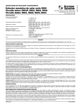
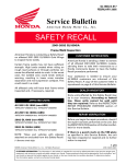
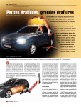
1
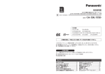
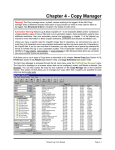
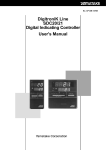
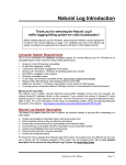
Electronic Curemaster
SERVICE MANUAL
ETS2d (S214d, S221d, S240d)
ETS3d (S310d, S321d)
ETS5d (S516d, S521d)
IF IN ANY DOUBT CONTACT:
EDWIN TRISK LIMITED.
FORM FM 339
ISSUE 09 (VALID FROM 20/10/06)
© Edwin Trisk Ltd.2006
FM 339
Page 1 of 35
IMPORTANT
PLEASE READ THESE INSTRUCTIONS THOROUGHLY
BEFORE COMMENCING ASSEMBLY OR OPERATION OF
THE UNIT. FAILURE TO DO SO COULD RESULT IN
DAMAGE OR INJURY FOR WHICH EDWIN TRISK LIMITED
WILL ACCEPT NO RESPONSIBILITY OR LIABILITY.
ISOLATE MAINS SUPPLY BEFORE REMOVING COVERS.
THE SUPPORT ARM EXTENDS FIERCELY WHEN CASSETTE ASSEMBLY
IS NOT FITTED.
THIS MANUAL (ISSUE 05) IS ONLY INTENDED FOR THE SERVICING OF
THE MODELS MENTIONED ON THE FIRST PAGE.
THIS MANUAL IS AN UNCONTROLLED DOCUMENT. TRISK RESERVE
THE RIGHT TO UPDATE UNIT SPECIFICATIONS WITHOUT PRIOR
NOTICE OR CONSULTATION.
PLEASE READ THE RELEVANT REPAIR PROCEDURE THOROUGHLY AT
LEAST ONCE BEFORE COMMENCING ANY SERVICING OPERATION.
SERVICING OPERATIONS SHOULD ONLY BE CARRIED OUT BY
QUALIFIED SERVICE PERSONNEL WHO MUST USE TRISK APPROVED
COMPONENTS.
FM339
Page 2 of 35
CONTENTS
INTRODUCTION ...........................................................................................................................4
Servicing Tools.............................................................................................................................4
TECHNICAL SPECIFICATIONS..................................................................................................5
MAJOR COMPONENTS................................................................................................................6
Base – (All Units).........................................................................................................................7
Arm & Upright Assemblies (S214d, S221d, S240d) ...................................................................8
Arm & Upright Assemblies (S310d)..........................................................................................10
Arm & Upright Assemblies (S321d)..........................................................................................11
Arm & Upright Assemblies (S321d)..........................................................................................12
Arm & Upright Assemblies (S516d)..........................................................................................14
Arm & Upright Assemblies (S521d)..........................................................................................16
Cassette Assembly (S221d, S240d, S214d) ...............................................................................18
Cassette Assembly (S310d, S321d) ...........................................................................................19
Cassette Assembly (S516d, S521d) ...........................................................................................20
I R Cassette Assembly (S214d, S221d, S240d, S516d, S521d).................................................22
I R Cassette Assembly (S310d, S321d)......................................................................................24
Distance Indicator Exploded Assembly .....................................................................................26
FAULT FINDING GUIDE ...........................................................................................................27
FAULT FINDING FLOW DIAGRAM ........................................................................................28
REPAIR PROCEDURES ..............................................................................................................32
Procedure 1- FRONT PANEL REMOVAL...............................................................................32
Procedure 2 – MAINS CABLE REPLACEMENT....................................................................32
Procedure 3 – CASSETTE CORD REPLACEMENT*.............................................................32
Procedure 4 – UPM REPLACEMENT (UNIVERSAL POWER MODULE)...........................33
Procedure 5 – MAIN CONTROL PCB REPLACEMENT........................................................33
Procedure 6 – IEC SOCKET REPLACEMENT........................................................................33
Procedure 7 – GAS STRUT REPLACEMENT .........................................................................33
Procedure 8 – I.R EMITTER REPLACEMENT .......................................................................34
FM339
Page 3 of 35
INTRODUCTION
This manual is intended to aid the servicing of the TRISK branded products listed on the cover.
Servicing operations should only be carried out by qualified service personnel, who must use
TRISK approved components. Although every effort has been made to ensure that the following
information is accurate, it is only intended to help service personnel rather than direct them in
their every step. It is vitally important that any problems encountered when servicing units are
referred to your importer or Edwin Trisk Ltd.
PLEASE NOTE THAT WHEN SERVICING THE UNIT, REFER TO SECTION 5 - FAULT
FINDING GUIDE, BEFORE COMMENCING ANY REPAIR PROCEDURE.
Servicing Tools
The following tools are the minimum required to service the range of products listed on the front
cover:
No. Required
Description
1
1
1
2
2
1
1
1
1
1
1
1
1
Round, Parallel Tipped 3mm, Screwdriver
Round, Parallel Tipped 5mm, Screwdriver
Round, Supadrive No. 1, Screwdriver
19mm Combination Spanners
17mm Combination Spanners
Hand Drill
Drill 3mm diameter
Combination Pliers
Wire Strippers / Cutters
Allen Key (6mm AF)
Crimp Tool for Crimping Red, Blue and Yellow Insulated Crimp Connections
Hand Rivet Gun with nozzle for 3mm rivets.
Heyco Hand-pliers
FM339
Page 4 of 35
TECHNICAL SPECIFICATIONS
All units use quartz, tungsten filament ruby sleeved Infra-Red Emitters.
All units can operate from a 50Hz or 60Hz mains supply.
ETS214d & ETS240d
Rated Voltage
Maximum Power Consumption (Nominal)
240V, Single Phase
3000W
ETS221d
Rated Voltage
Maximum Power Consumption (Nominal)
230V, Single Phase
3300W
ETS310d
Rated Voltage
Maximum Power Consumption (Nominal)
240V, Single Phase
4500W
ETS321d
Rated Voltage
Maximum Power Consumption (Nominal)
400V, Three Phase
4500W
ETS516d
Rated Voltage
Maximum Power Consumption (Nominal)
240V, Single Phase
6000W
ETS521d
Rated Voltage
Maximum Power Consumption (Nominal)
400V, Three Phase
6600W
FM339
Page 5 of 35
MAJOR COMPONENTS
1 BASE
2 UPRIGHT/ARM ASSEMBLY
3 IR CASSETTE/BACKBAR ASSEMBLY
4 IR CASSETTE – TOP
5 IR CASSETTE – CENTRE & BOTTOM
FM339
Page 6 of 35
Base – (All Units)
PART NUMBER
DESCRIPTION
1
E214.01
E221.01
E321.01
E521.01
BASE
2
S8031
WASHER, M10
3
S0293A
LOCKNUT, M10 – NYLOC
4
S0075D
END CAP – PLASTIC
5
S0065
BRAKED CASTOR
6
S0064
UNBRAKED CASTOR
(S214d)
(S221d, S240d, S310d)
(S321d, S516)
(S521d)
FM339
Page 7 of 35
Arm & Upright Assemblies (S214d, S221d, S240d)
1
2
3
4
5
6
7
8
9
10
11
12
13
14
15
16
17
18
19
20
21
22
D220-03-20
S0227
121.07
S0161
S0256
E221.04.05
E214.04.04
E221.04.04
E240.04.04
S0191
370.08
S0195A
350.01
S0512
351.01
S0513
E221.04.01
E214.04.01
126.10
S0173C
S0174
S0308A
S0308
S0291
E221.03.03
121.07
321.06
E221.03.25
D320.03.15
S0269
Front Panel Fascia Label
Timer Knob
No.6 x 3/8” Self Tapping Screw
15A MCB – Single Pole
M3 X 8 Taptite P021 Screw
Front Panel Fascia Metalwork
Mains Cable Input Plate Assembly
Cable 14AWG 3 Core Cable
Cable – Schuko Cord Set
Cable 1.5 mm 3 Core
Stress Relief Gland
Gland Nut
Con Clamp
Main Control PCB
M4 x 10 Pan-head Screws
Connector Block 20A
Connector Block 30A
M5 Star Washer
M5 Plain Washer
M5 Nut
Transformer PCB Assembly
No.6 x 3/8 “ Self Tapper
Single Phase 16A Filter
Top plate – (US units only)
Universal Power Module (UPM)
M5 x 16 Bolt
Note
(214)
(221)
(240)
(214)
(221)
(240)
(214)
(221,240)
(214)
(221,240)
(221,240)
(214)
(Note 1)
(221,240)
(214)
23
24
25
26
27
28
29
30
31
32
33
34
35
36
37
38
39
40
41
42
43
44
45
46
47
48
49
50
108.04
PDD003X
S8027A
T1040
S0330
PDD040Y
E221.06.02
D310.02.01
D320.06.18
372.03
S0275
PDD 040X
PDD 131
S0294A
S0076
T1011
177.01
S0112
S0117
E221.02.01
S0118
M10 x 15 Button Head Screw (x4)
Column U-Channel
Spiral Pins Ø10 x 50
Plastic Handle (Large)
Rivet Ø4.8 x 15
Top End Cap (Socket Housing)
Single Socket Housing
Single Socket Housing
Distance Indicator Arm Cable
IEC Outlet Socket (x3)
M12 x 90 Bolt
Bottom End Cap (Skt. Housing)
Pivot Bolt Assembly
Nut, M12, Nyloc
Nut Cap M12
Ratchet Lever M12 (Female)
5/16” Capped Starlock
800N Gas Strut
Gas Strut Lever
Gas strut End
Lever Grip
PDD 011
PDD033
194.01
D320.03.36
E221.02.21
Pivot Bracket Assembly
Gas Strut Pin
Spacer
Gas Strut Arm Pin
Top Cap
(221,240)
(214)
(214, 221, 240)
On S214d item 17 is to be found at top of upright.
FM 339
Page 8 of 35
FM339
Page 9 of 35
Arm & Upright Assemblies (S310d)
1
2
3
4
5
6
7
8
9
10
11
12
13
14
15
16
17
18
19
20
21
22
23
24
25
26
27
D220-03-20
S0227
121.07
S0162
S0256
E310.04.05
E310.04.04
S0191A
350.02
351.02
E221.04.01
126.10
S0174
S0308A
S0308
S0291
E221.03.03
121.07
E221.03.25
D320.03.15
S0269
108.04
PDD003X
S8027A
T1040
S0330
Front Panel Fascia Label
Timer Knob
No.6 x 3/8” Self Tapping Screw
30A MCB – Single Pole
M3 X 8 Taptite P021 Screw
Front Panel Fascia Metalwork
Mains Cable Input Plate Assembly
Cable 10 AWG 3 Core Cable
Stress Relief Gland
Gland Nut
Main Control PCB
M4 x 10 Pan-head Screws
Connector Block 30A
M5 Star Washer
M5 Plain Washer
M5 Nut
Transformer PCB Assembly
No.6 x 3/8 “ Self Tapper
Top plate
Universal Power Module (UPM)
M5 x 16 Bolt
M10 x 15 Button Head Screw (x4)
Column U-Channel
Spiral Pins Ø10 x 50
Plastic Handle (Large)
Rivet Ø4.8 x 15
Note
(Note 1)
28
29
30
31
32
33
34
35
36
37
38
39
40
41
42
43
44
45
46
47
48
49
50
51
52
53
PDD040Y
D310.02.01
D320.06.18
372.03
S0275
PDD 040X
PDD 131
S0294A
S0076
T1011
177.01
550.03
S0117
E221.02.01
S0118
Top End Cap (Socket Housing)
Single Socket Housing
Distance Indicator Arm Cable
IEC Outlet Socket (x3)
M12 x 90 Bolt
Bottom End Cap (Skt. Housing)
Pivot Bolt Assembly
Nut, M12, Nyloc
Nut Cap M12
Ratchet Lever M12 (Female)
5/16” Capped Starlock
1200N Gas Strut
Gas Strut Lever
Gas strut End
Lever Grip
PDD 011
PDD033
194.01
D320.03.36
E221.02.21
PDD220
320.01
S0180A
Pivot Bracket Assembly
Gas Strut Pin
Spacer
Gas Strut Arm Pin
Top Cap
Label ‘Fuse Rating’
Fuse Holder 30A 250Vac
Fuse, 15A time delay
On S310d item 17 is to be found at top of upright.
FM339
Page 10 of 35
FM339
Page 11 of 35
Arm & Upright Assemblies (S321d)
1
D320.03.20
Front Panel Fascia Label
27
108.04
M10 x 15 Button Head Screw
2
S0227
Timer Knob
28
T1040
Plastic Handle Large
3
121.07
No.6 x 3/8” Self Tapping Screw
29
S0330
4
S0163
10A 3 phase MCB
30
PDD040Y
Rivet Ø4.8 x 15
Top End Cap (Socket Housing)
5
E521.03.22
Breaker Bracket
31
E221.06.02
Single Socket Housing
6
E321.04.06
Front Panel Fascia Metalwork
32
D320.06.18
Distance Indicator Arm Cable
7
E214.04.04
Mains Cable Input Plate Assembly
33
S0275
M12 x 90 Bolt
8
S0173C
Terminal Block 20A
34
PDD040X
Bottom End Cap (Socket Housing)
9
T1050A
Plug – 16A 5Pin CEE17
35
PDD131
Pivot Bolt Assembly
10
300.10
Cable 1.5mm 4 – Core
36
S0294A
Nut M12, Nyloc
11
S0512
Stress Relief Gland
37
S0076
Nut Cap M12
12
S0513
Con Clamp
38
T1011
M12 Ratchet Lever (Female)
13
E321.04.01
S321d Main Control PCB
39
372.03
IEC Socket (x3)
14
126.10
M4 x 10 Pan Head Screws
40
177.01
5/16” Capped starlock
15
S0291
M5 Nut
41
550.03
1200N Gas Strut
16
S0308
M5 Plain Washer
42
S0117
Gas Strut Lever
17
S0308A
M5 Star Washer
43
E221.02.01
Gas Strut End
18
E321.03.03
Transformer Assembly
44
194.01
Spacer
19
121.07
No.6 x 3/8 “ Self Tapping Screw
45
D320.03.36
Gas Strut Arm Pin
20
321.02
3 Phase 16A Mains Filter
46
21
E221.02.21
Top Cap
47
PDD033
Pin
22
D320.03.15
Universal Power Module (UPM)
48
S0118
Lever Grip
23
S0269
M5 x 16 Bolt
49
24
S8027A
50
26
PDD 003X
Spiral Pins Ø10 x 50
Column U-Channel
51
FM339
Page 12 of 35
FM339
Page 13 of 35
Arm & Upright Assemblies (S516d)
1
2
3
4
5
6
7
8
9
10
11
12
13
14
15
16
17
18
19
20
21
22
23
24
25
E521.04.23
S0227
121.07
S0162
S0256
E516.04.05
E516.04.04
S0240B
S0191A
350.08
351.02
E221.04.01
126.10
E221.03.03
S0291
S0308A
S0308
320.01
S0180A
S0217B
E221.02.21
D320.03.15
S0269
T1040
S0330
Front Panel Fascia Label
Timer Knob
No.6 x 3/8” Self Tapping Screw
MCB 1 Phase 30A
M3 x 8 Taptite Pozi Screw
Front Panel Fascia Metalwork
Mains Cable Input Plate Assembly Inc Cable
Plug Hubble Twist Lock 30A
Cable – 10AWG 3 Core
Stress Relief Gland
Gland Nut
Main Control PCB
M4 x 10 Panhead Screws
Transformer PCB Assembly
M5 Nut
M5 Star Washer
M5 Plain Washer
Fuse Holder, 30A 250V
Fuse 15A Time Delay
Heatshrink Sleeving 6.4dia
Top Cap
Universal Power Module (UPM)
M5 x 16 Bolt
Plastic Handle (Large)
Rivet Ø4.8 x 15
26
27
28
29
30
31
32
33
34
35
36
37
38
39
40
41
42
43
44
45
46
47
48
49
PDD040Y
E516.06.03
D320.06.18
372.03
S0275
01.04.07
S0294A
S0076
177.01
S0115
S0117
E221.02.01
S0118
Top End Cap (Socket Housing)
Socket Housing Cover
Distance Indicator Arm Cable
IEC Outlet Socket (x6)
M12 x 90 Bolt
Bottom End Cap (Socket Housing)
M12 Nut, Nyloc
M12 Nut Cap
5/16” Capped Starlock
1500 N Gas Strut
Gas Strut Lever
Gas Strut End
Lever Grip
PDD033
194.01
D320.03.36
S8027A
PDD003X
108.04
S0174
Pin
Spacer
Gas Strut Arm Pin
Spirol pin
Column U-Channel
M10 x 15 Button Head Screw (x4)
Connector block 30A
FM339
Page 14 of 35
FM339
Page 15 of 35
Arm & Upright Assemblies (S521d)
Spiral Pin Ø10 x 50
Plastic Handle (Large)
1
E521.04.23
Front Panel Fascia Label
25
S8027A
2
S0227
Timer Knob
26
T1040
3
121.06
No.6 x 3/8” Self Tapping Screw
27
S0330
4
S0163
MCB 3 Phase 10A
28
PDD040Y
Rivet Ø4.8 x 15
Top End Cap (Socket Housing)
5
E521.03.22
MCB Bracket
29
E521.06.02
6 Outlet Socket Housing
6
E521.04.06
Front Panel Fascia Metalwork
30
D320.06.18
Distance Indicator Arm Cable
7
E521.04.04
Mains Cable Input Plate Assembly, Inc Cable
31
372.03
IEC Outlet Socket (x6)
8
T1050A
Plug 5 Pin CEE17
32
S0275
M12 x 90 Bolt
9
300.10
Cable 1.5mm² 3-core H05-VV-F4
33
PDD040X
Bottom End Cap (Socket Housing)
10
S0512
Stress Relief Gland
34
S0294A
M12 Nut, Nyloc
11
S0513
Con Clamp
35
S0076
M12 Nut Cap
12
E521.04.01
E521 Main Control PCB
36
177.01
5/16” Capped Starlock
13
126.10
M4 x 10 Panhead Screws
37
S0115
1500 N Gas Strut
14
E521.03.03
Transformer PCB Assembly
38
S0117
Gas Strut Lever
15
S0291
M5 Nut
39
E221.02.01
Gas Strut End
16
S0308A
M5 Star Washer
40
S0118
Lever Grip
17
S0308
M5 Plain Washer
41
18
121.06
No.6 x 3/8” Self Tapping Screw
42
19
321.08
3Phase 16A Mains Filter
43
20
E221.02.21
Top Cap
44
21
D320.03.15
Universal Power Module (UPM)(x2)
45
PDD033
Pin
22
S0269
M5 x 16 Bolt
46
194.01
Spacer
23
108.04
M10 x 15 Button Head Screw (x4)
47
D320.03.36
Gas Strut Arm Pin
24
PDD003X
Column U-Channel
48
S0173C
Terminal Block (20A)
FM339
Page 16 of 35
FM339
Page 17 of 35
Cassette Assembly (S221d, S240d, S214d)
FM339
Page 18 of 35
Cassette Assembly (S310d, S321d)
FM339
Page 19 of 35
Cassette Assembly (S516d, S521d)
FM339
Page 20 of 35
This page left blank intentionally
FM339
Page 21 of 35
I R Cassette Assembly (S214d, S221d, S240d, S516d, S521d)
1
2
3
4
5
6
7
8
9
10
11
12
13
14
PDD 072
S0251
PDD 006Y
PDD 006W
PDD 007X
CM01.05.20
350.05
S0173C
S0256
PDD 082
PDD 021
370.05
370.20
Die Cast End Cap
Screw, Pozi-pan, Self-tapping
Cassette Side Extrusion
Cassette Back
Back Reflector, long
Strain Relief Plate
Flexi-strain Relief Grommet
Terminal Block, 3-way, 20A
Screw, Pozi-taptite
Cassette Cable Tray
Side Reflector
Plug/Cordset (S221d, S240d)
Plug/Cordset (S214d, S516d, S521d)
2
8
2
1
1
1
1
1
3
1
2
1
S0321A
380.08
Washer, M8, Shakeproof (NUT FIX ONLY)
Infrared Emitter Tube, 230V, 1100W
(S221d, S521d)
Infrared Emitter Tube, 240V, 1000W
(S214d, S240d, S516d)
Grille (S221d
Grille (S214d
Socket head cap Screw, M8x50
(NUT FIX ONLY)
Rivet Ø3.2 x 8
Rivet Ø3.2 x 8 (Black)
Shakeproof Washer M3
1
1
380.07
15
16
PDD 161
PDD 005X
S 8049
17
18
19
S0332
S0328A
S0309
20
21
22
23
24
25
26
27
28
S0206
29
301.26
S0205B
1
4
6
4
301.25
S0205
30
2
S8008
S0561H
S0220A
395.02
S0220
PDD 196
S0211B
S0212
301.24
31
32
33
34
35
36
S0210
S0217
S0215
S0349
385.01
PDD 166
Cable clip
Tube packer
Snap-in Cable Tie
Cable Tie Base
Cable Tie
Label – ‘ISOLATE MAINS’
Male Insulated Coupler
Shrouded Receptacle - red
Cable 1.0mm Brown, High Temp.
(S226d, S240d, S521d)
Cable 1.0mm Brown Tri-Rated.
(S214d, S516d)
2
3
4
1
1
1
2
2
600mm
Cable 1.0mm Blue High Temp.
(S226d, S240d, S521d)
Cable 1.0mm Blue Tri-Rated
(S214d, S516d)
390mm
Cable 1.0mm Grn/Yel High Temp.
(S226d, S240d, S521d)
Cable 1.0mm Grn/Yel Tri-Rated
(S226d, S240d, S521d)
M3 Red Ring Crimp Terminal
Heatproof Sleeving
Red Blade Crimp Terminal
Terminal Block Retaining Pin
Heatproof Sleeving 3Ø
Label – ‘CAUTION, REMOVE
PACKING’
600mm
7
100mm
4
1
450mm
1
FM339
Page 22 of 35
I R Cassette Assembly (S214d,S221d,S240d,S516d,S521d)
FM339
Page 23 of 35
I R Cassette Assembly (S310d, S321d)
1
2
3
4
5
6
7
8
10
11
S330.05.20
S330.05.21
S330.05.22
S320.05 20
S330.05.23
S330.05.24
PDD 021
PDD 072
CM01.05.20
PDD 026
PDD 167
12
13
14
PDD 041
15
16
17
18
19
20
21
370.05
S0173C
S0349
350.05
S0256
S0251
S8049
380.11
Cassette back
Back Reflector
Grille (S310d)
Grille (S321d)
Cassette Cable Tray
Cassette Side Extrusion
Side Reflector
Die Cast End Cap
Strain Relief Plate
Label – ‘INSPECTED BY’
Label – ‘CAUTION, REMOVE
PACKING’
Label - “ISOLATE MAINS”
Infrared Emitter Tube, 240V
1500W
Plug/Cordset
Terminal Block, 3-way, 20A
Terminal block retaining pin
Flexi-strain Relief Grommet
Screw, Pozi-taptite M3x8
Screw, Pozi-pan, Self Tapping
Socket headcap Screw
(NUT FIX ONLY)
1
1
1
22
23
24
S0332
S0328A
S0321A
1
2
2
2
1
1
1
25
26
27
28
29
30
31
32
33
34
35
36
S0309
395.02
S0220
S8008
S0220A
Rivet Ø3.2x8
Rivet Ø 3.2 x 8 (Black)
Washer, shakeproof M8
(NUT FIX ONLY)
Washer shakeproof M3
Cable Tie Base
Cable Tie
Cable Clip
Snap-in Cable Tie
S0211B
S0212
S0210
S0215
S0206
301.24
S0205
301.25
S0205B
301.26
385.01
S0217
Red Male Coupler
Red Shrouded Receptacle
M£ Red Ring
Red Blade
Cable 1.0mm Brown Tri-Rated (S310d)
Cable 1.0mm Brown High Temp (S321d)
Cable 1.0mm Blue Tri-Rated (S310d)
Cable 1.0mm Blue High Temp (S321d)
Cable 1.0mm Grn/Yel Tri-Rated (S310d)
Cable 1.0mm Grn/Yel High Temp (S321d)
Heatproof Sleeve Ø3
Heatproof SLeeve Ø6
1
1
1
1
1
1
3
8
2
37
38
39
40
2
6
2
4
1
1
1
6
2
2
730mm
520mm
730mm
450mm
100mm
FM339
Page 24 of 35
I R Cassette Assembly (S310d,S321d)
FM339
Page 25 of 35
Distance Indicator Exploded Assembly
1
D220.05.18
Distance indicator cable assembly
2
D220.05.20
Distance indicator label
3
S8007
Cable strain relief gland
4
D320.05.12
D321.05.02
Back-plate assembly (inc. items 1,2,3,4) (S214, S221, S240, S516, S521)
Back-plate assembly (Inc items 1,2,3,4) (S310, S321)
5
D320.05.03
Distance indicator PCB
6
D320.05.25
Sensor mounting plate
7
D320.05.10
Sliding cover assembly
8
D220.05.22
Distance indicator extrusion (S214, S221, S240, S516, S521)
D320.05.22 Distance indicator extrusion (S310, S321)
FM339
Page 26 of 35
FAULT FINDING GUIDE
Fault:
INFRA RED EMITTERS WILL NOT TURN OFF or INFRA RED EMITTERS TURN ON
IMMEDIATELY THE MAIN POWER SWITCH IS TURNED ON.
The Universal Power Module (UPM) has failed. See procedure 1 - Front Panel Removal and
procedure 4 - UPM Replacement.
Fault:
ARM WILL NOT RAISE OR LOWER
Gas Strut Locknut slack, causing unit to jam. To reset, rotate Gas Strut Shaft one half turn clockwise
and check operation with release arm. Continue this operation until a position is obtained which
allows the arm to move freely up and down when the Gas Strut Lever is depressed. Tighten Locknut.
If examination of the Gas Strut reveals damage to the unit e.g. Bent Shaft, see procedure 7, Gas Strut
Replacement.
FM339
Page 27 of 35
FAULT FINDING FLOW DIAGRAM
Does main timer
display light up?
Does the unit display time
setting and stay silent when
switched on?
Go to page 30
Do all Infra Red lamps illuminate
when timer enabled?
Go to page 32
Go to page 31
Hints and Tips
When checking for connection or wiring faults, try moving and bending the wire around. An insecure connection will give an
intermittent fault.
If all the wiring seems to be good, check the circuit boards for dry or cracked solder joints.
Severe bends and kinks in cables are prone to snapping interior wiring. Melted outer shielding of the mains cable may also be a cause of
malfunction.
When checking IEC cable for continuity, the resistance across the Live and Neutral of the cable and lamp set should read ≥3.5Ω when
cold and ≤16.0Ω just after use.
The Universal Power Module (UPM) is the black component situated approximately 1/3 of the way down the interior of the upright,
marked D320.03.15 on reverse of board.
FM339
Page 28 of 35
Does main timer display light up?
Check continuity from mains plug to transformer board in
upright:
E pin on plug to E point in upright
L pin on plug to ON/OFF switch
Other side of ON/OFF switch to SP2 on transformer board
N pin on plug to SP1 on transformer board
Check continuity from SP3 &
SP4 on transformer board in
upright to main control board
fixed to fascia
Swap main
control board
Check following connections and
continuity:
>Fuse on transformer board in upright
>Transformer windings
>L IN to L OUT in filter
>N IN to N OUT in filter
Also check for short circuit between all L
and N in filter
Correct wiring and/or
connection faults
Replace faulty
components
Correct wiring and/or
connection faults
FM339
Page 29 of 35
Does the unit display time setting and stay silent when switched on?
Check distance
indicator is connected
Timer shows lines across
centre
Inspect distance indicator
cable and its plug and
socket for damage
Check continuity
between distance
indicator socket on
end of arm and CON1
on main control board
Connect distance
indicator
Correct wiring and/or
connection faults
Change distance
indictor cable set
FM339
Page 30 of 35
Do all Infra Red lamps illuminate during Flashoff?
Do any lamps
illuminate?
Check visually that
tubes are intact
Check continuity of IEC cable
of OFF lamp:
Unplug corresponding cable and
plug back in to alternative
socket on end of arm
Check continuity of IEC cable
between L and N in cable socket
Change tubes
Check continuity between:
>Input N and end of arm
>Input L and 1,2 & 3 IN
on UPM in upright
>OUT 1, 2 & 3 on UPM
in upright and L out at end
of arm
>C on UPM in upright
and SP4 on main control
board
>S1, S2 & S3 on UPM
and SP5, SP6 & SP7 on
main control board in
upright
Change UPM
Change IEC
cable
Correct wiring and/or
connection fault
FM339
Page 31 of 35
REPAIR PROCEDURES
Procedure 1- FRONT PANEL REMOVAL
Ensure unit is disconnected from mains supply.
Remove cassette assembly.
Remove upright from base to allow the plastic side strips to be removed. Undo the four screws
holding the top cap in position. Remove the four remaining screws holding the front fascia in position.
The front fascia can now pivot forward allowing access to the components inside.
Procedure 2 – MAINS CABLE REPLACEMENT
Ensure unit is disconnected from mains supply (remove mains plug from the supply).
Remove the six screws that hold the cable gland cover to the upright column. The cover can be eased
away from the column exposing the connections to the mains cable. Disconnect the mains input cable
from the terminal block.
Release the clamping screws on the cable clamps and cut the tie wrap holding the cable to the terminal
block. Disconnect the earth cable from the cover earth stud. Undo the clamping nut on the spiral
gland to release the old mains lead.
To refit the new mains cable, ensure the new cable is the same type as the original. Strip the sheath
270mm back from the end before inserting into the cable gland. Fasten the cable clamp onto the
sheath of the mains cable allowing a minimum of 5mm to extend beyond the clamp. Refit the cable tie
to tidy cables. Tighten nut of spiral gland. Connect as below:
(S221d, S240d)
Brown
- Live (Terminal marked L)
Blue
- Neutral (Terminal marked N)
Green/Yellow - Earth (Terminal marked E)
(S321d, S521d)
Brown
- Phase 1 (Terminal marked L1)
Black
- Phase 2 (Terminal marked L2)
Blue
- Phase 3 (Terminal marked L3)
Green/Yellow - Earth (Terminal marked E)
(S214d, S310d, S516d)
Black
- Live (Terminal marked L)
White
- Neutral (Terminal marked N)
Green
- Earth (Terminal marked E)
Procedure 3 – CASSETTE CORD REPLACEMENT*
*The Cassette Cord is usually supplied as part of a spares package, complete with Strain Relief Plate
and associated components. The following procedure details the steps of replacing just the Cassette
Cord itself.
Ensure unit is disconnected from the mains supply.
FM339
Page 32 of 35
Disconnect Cassette Cords from IEC Sockets. Remove the affected I.R. Cassette Assembly from the
end of the arm by removing the ratchet lever. Carefully support I.R. Cassette Assembly and slide this
unit off the pivot bolt.
Examination of the rear of the affected I.R Cassette will show the cord entering the unit via a spiral
gland mounted on a Strain Relief Plate. Drill out the four rivets which hold the Strain Relief Plate to
the Back Mesh, and the central rivet that holds the Earth Terminal to the Strain Relief Plate.
A record should be made of the connections to the Terminal Block before removing old cable.
A pair of Heyco hand pliers are usually required for removing and fitting the Spiral Gland but normal
can be used if necessary. Fit new cord. Re-attach the cassette earth terminal. Rivet the Strain Relief
Plate onto Back Mesh. The unit is now ready for re-assembly
Procedure 4 – UPM REPLACEMENT (UNIVERSAL POWER MODULE)
Ensure unit is disconnected from the mains supply.
See procedure 1 for removal of front panel.
Do not disconnect the old UPM until the new one is in place. The UPM can be swapped by first
removing the two securing screws. The new UPM can then be fixed into position, (once thermally
conductive paste has been applied). The cabling can then be swapped over, being careful to connect
correctly.
Procedure 5 – MAIN CONTROL PCB REPLACEMENT
Ensure unit is disconnected from the mains supply.
See procedure 1 for removal of front panel.
Do not disconnect the old control PCB until the new one is in place. Undo the M3 nut located near the six pin connector.
Undo the six screws fixing the control PCB to the front panel. Remove knobs on front of panel. Fix new control PCB in
position and carefully swap the interconnections from the old control PCB to the new.
Procedure 6 – IEC SOCKET REPLACEMENT
Ensure unit is disconnected from mains supply.
Remove cassette assembly / pivot bolt assembly.
To remove the plastic covers at the end of the arm undo the 8 screws fixing them.
Remove Plastic Caps, which cover bolts that attach socket housing to arm ‘U’ Channel. Slacken M10
Lock-nuts sufficiently to allow the Socket Housing to slide off and give access to the sockets. Do not
use excessive force or the wires will be damaged.
Take a note of the wiring connections to the damaged socket then remove wires and unclip socket.
Clip the new socket into housing and refit cables. Refit Socket Housing to arm.
Procedure 7 – GAS STRUT REPLACEMENT
Ensure unit is disconnected from mains supply.
Check rating of replacement Gas Strut is correct (if in doubt, check rating on old gas strut).
Remove cassette assembly, remove upright from base and remove side strips.
Remove the self – tapping screws that secure the Plastic Cap on the top of Upright. Remove the 2
plastic covers from the side of the Upright.
Carefully support the cassette assembly on a stand or bench.
FM339
Page 33 of 35
Remove the capped starlock from one side of the pin assembly that fasten the Gas Strut to the support
arm. (A new capped starlock will probably be needed)
Push out the lower Gas Strut Pivot Pin. Rotate the Gas Strut and remove from the Upright.
Replace with a TRISK pre-prepared Gas Strut. Replace the lower Gas Strut Pivot Pin.
Adjust the support arm height to suit the new Gas Strut setting. Reassemble holding collar arrangement
and fix in place with new split pin.
CAUTION: Once fitted, Gas Strut should only be tested with I.R. Cassettes in place.
Check that Gas Strut operation is satisfactory.
Procedure 8 – I.R EMITTER REPLACEMENT
Check that replacement emitter has correct voltage and wattage ratings.. Check old emitter end caps if
in doubt.
Ensure unit is disconnected from mains supply.
Remove wire Grille from front of I.R Cassette.
Remove Self Tapping Screws which hold Side Reflectors onto cassette. A small screwdriver will be
necessary to lift the side reflector from the cassette.
When the Side Reflectors are removed, take note of the cable positions before removing old emitter.
The In-Line connector can be separated by hand, but a better solution is to use two pairs of pliers. One
to hold each connector when separating the wires.
Fit new Infra-Red Emitter to sockets in cassette. To avoid touching the ruby sleeve with bare hands
use tissue paper when handling the emitter.
Reconnect Infra-Red Emitter to cassette wiring, taking care to replace the wires in the original
positions.
Fit side reflectors then clean ruby sleeve and Reflectors with IPA or Methylated Spirits.
Refit Grille.
Allow 15 minutes for the solvent to dissipate before switching on.
FM339
Page 34 of 35
FM 339
ISSUE 9
© Edwin Trisk Ltd 2006
EDWIN TRISK LTD
8 – 9 BLEZARD BUSINESS PARK
SEATON BURN
NEWCASTLE UPON TYNE
TYNE & WEAR
NE13 6DS
UNITED KINGDOM
TEL: +44 (0) 845 113 5522
FAX: +44 (0) 845 113 5511
E-mail: [email protected]
Web: www.trisk.co.uk
FM339
Page 35 of 35