1
DISASSEMBLY INSTRUCTIONS
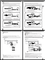
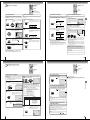
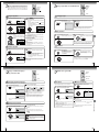
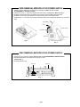
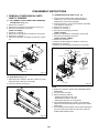
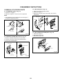
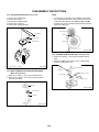
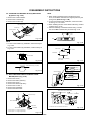
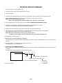
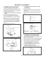
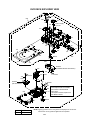
2-13: CAPSTAN DD UNIT (Refer to Fig. 2-13)
NOTE
1.
2.
3.
4.
5.
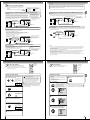
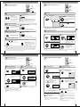
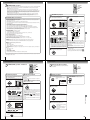
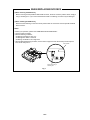
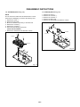
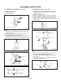
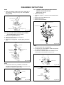
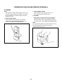
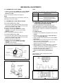
1. In case of the Pinch Roller Cam and Main Cam installation, install them as shown in the circled section of Fig. 214-B so that the markers meet. (Refer to Fig. 2-14-B)
And also can be seen the Main Chassis hole through the
Main Cam maker hole.
Remove the Capstan Belt.
Remove the screw 1.
Remove the Capstan Holder.
Remove the 3 screws 2.
Remove the Capstan DD Unit.
Pinch Roller Cam
Capstan Belt
Marker
1
Capstan Holder
Capstan DD Unit
Main Cam
Fig. 2-14-B
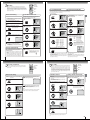
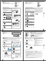
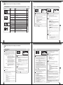
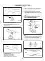
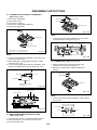
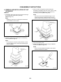
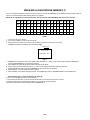
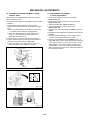
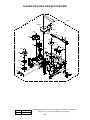
2-15: LOADING GEAR S/T UNIT (Refer to Fig. 2-15-A)
2
1. Remove the E-Ring 1 and remove the Main Loading
Gear.
2. Remove the Main Rod, Tension Lever, Loading Arm S
Unit and Loading Arm T Unit.
22
• Screw Torque: 4 ± 0.5kgf•cm
1
Fig. 2-13
Main Loading Gear
Main Rod
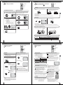
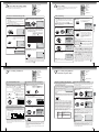
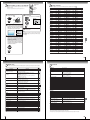
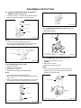
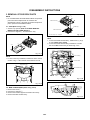
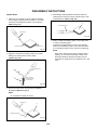
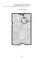
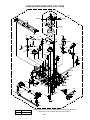
2-14: MAIN CAM/PINCH ROLLER CAM/JOINT GEAR
(Refer to Fig. 2-14-A)
Loading Arm T Unit
Tension Lever
1. Remove the E-Ring 1, then remove the Main Cam.
2. Remove the E-Ring 2, then remove the Pinch Roller
Cam and Joint Gear.
Loading Arm S Unit
1
Main Cam
Fig. 2-15-A
2
Pinch Roller Cam
Joint Gear
Fig. 2-14-A
B2-5