1
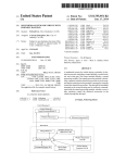
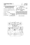
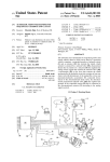
United States Patent [191
[11]
[45]
Masuda
[54] AUTOMATIC SPEED CONTROL SYSTEM
FOR MOTORCYCLES
[75] Inventor:
Iwata, Japan
[21] Appl. No.: 261,130
[22] Filed:
[56]
Oct. 24, 1988
[62]
4,796,716, which is a division of Ser. No. 645,494, Aug.
29, 1984, Pat. No. 4,587,937.
[30]
Foreign Application Priority Data
Aug. 31, 1989 [JP]
[51]
[52]
Japan ............................. .. 58-1600037
Int. Cl.5 ..................... .. B60K 31/18; B60K 31/00
US. Cl. .................................. .. 180/171; 180/170;
'
[58]
180/219; 340/441
Oct. 30, 1990
References Cited
4,133,407
l/ 1979
Schantz ............................. .. 180/ 177
OTHER PUBLICATIONS
Buick Chassis Service Manual, Buick Motor Div., GMC,
Flint, Mich., 10/1980, pp. Contents,, 8C4 and 9B1.
Primary Examiner-Albert W. Davis, Jr.
Attorney, Agent, or Firm—Ernest A. Beutler
[57]
Related US. Application Data
Division of Ser. No. 930,231, Nov. 13, 1986, Pat. No.
4,966,247
U.S. PATENT DOCUMENTS
Yutaka Masuda, Fukuroi, Japan
[73] Assignee: Yamana Hatsudoki Kabushiki Kaisha,
Patent Number:
Date of Patent:
ABSTRACT
An automatic speed control mechanism for a motorcy
cle that embodies a separately driven vacuum pump for
controlling the throttle valve of the motorcycle inde
pendently of its induction system vacuum. In addition,
an indicator system is provided that indicates when the
automatic speed control is operative and further which
indicates the preset speed and the actual speed of travel.
A manual arrangement is provided for manually over
riding the automatic speed control so as to reduce vehi
cle speed without disabling the automatic speed control
device.
Field of Search ............. .. 180/ 171, 176, 177, 170,
'
180/219; 340/54
2 Claims, 6 Drawing Sheets
US. Patent
Oct.30, 1990
Sheet 1 of6
4,966,247
US. Patent
Oct.30, 1990
Sheet 2 of 6
4,966,247
US. Patent
0ct.30, 1990
Sheet 3 of6
4,966,247
US. Patent
51
Oct.30, 1990
Sheet 4 of 6
4,966,247
US. Patent
Oct.30, 1990
Sheet 5 of 6
4,966,247
US. Patent
Oct.30,1\990
Sheet 6 0f 6
.Q/
' 97
-
93
4,966,247
1
4,966,247
AUTOMATIC SPEED CONTROL SYSTEM FOR
MOTORCYCLES
2
comprising throttle means for controlling vehicle speed,
operator control means for selectively positioning the
throttle means, and automatic speed control means for
operating the throttle means to operate the vehicle at a
This is a division of U.S. patent application Ser. No. 5 preset speed. In accordance with this feature of the
invention, power means powered independently of the
930,231, filed Nov. 13, 1986, now U.S. Pat. No.
induction system vacuum are incorporated as a part of
4,796,716 granted Jan. 10, 1989 which application was a
divisional of Ser. No. 645,494, filed Aug. 29, 1984 and
the automatic speed control means for operating the
has issued as U.S. Pat. No. 4,587,937 on May 13, 1986.
throttle valve.
Another feature of the invention is also adapted to be
BACKGROUND OF THE INVENTION
This invention relates to an automatic speed control
system for motorcycles and more particularly to an
improved power source for such automatic speed con
trols and an improved indicating system for such de
vices.
The use of automatic speed control devices, com
monly called “cruise controls”, has been widely ac
cepted with automobiles. Although such devices have
embodied in an automatic speed control for a motorcy
cle. Such an automatic speed control includes throttle
means for controlling the vehicle speed, operator con
trol means for selectively positioning the throttle means
and automatic speed control means for operating the
throttle means to operate the vehicle at a preset speed
under selective control of the operator. In accordance
with this feature of the invention, there is provided an
indicator of actual vehicle speed and an indicator of the
been applied primarily to automobiles, there are a num 20 preselected speed.
Yet another feature of the invention is also adapted to
ber of advantages to utilizing such systems in connec
be embodied in an automatic speed control for a motor
tion with motorcycles. Many of the automotive advan
cycle that includes throttle means for controlling the
tages apply equally well to motorcycles and, further
more, there are additional reasons why such devices are
vehicle speed, operator control means for selectively
particularly useful in connection with motorcycles. In
spite of their utility in motorcycle applications, there
25 positioning the throttle means and automatic speed
have been some factors which have precluded their use.
means to operate the vehicle at a preset speed. In accor
dance with this feature of the invention, indicator means
are provided for giving an indication of when the auto
For example, all of the typical automotive speed
control devices employ a vacuum motor for automati
control means for selectively operating the throttle
cally positioning the throttle valve of the engine to 30 matic speed control means is selectively operable.
maintain the vehicle speed at the preset value. Such a
BRIEF DESCRIPTION OF THE DRAWINGS
power source is not particularly adaptable for motorcy
FIG. 1 is a side elevational view of a motorcycle
cles since the motorcycle engine does not normally
having an automatic speed control mechanism con
provide sufficient induction system vacuum to operate
the throttle valve. In addition, the use of intake mani 35 structed in accordance with an embodiment of the in
'fold vacuum as the power source could adversely affect
the running of the motorcycle.
It is, therefore, a principal object of this invention to
provide an improved speed control device for a motor
cycle.
It is another object of this invention to provide a
motorcycle speed control that is independent of engine
induction system vacuum for its power.
It is a further object of this invention to provide an
improved vacuum power source for a speed control
system.
In an automotive speed control, the operator nor
mally removes his foot from the accelerator pedal dur
ing automatic speed control operation. With a motorcy
cle, on the other hand, the rider will normally keep his
hand on the accelerator handgrip even when operating
in a speed control mode. Furthermore, even when oper
ating in the speed control mode, it is desirable to permit
the rider to temporarily decelerate the motorcycle
without completing disabling the automatic speed con
trol.
It is, therefore, a further object of this invention to
provide an improved indicating device for indicating to
the rider when the speed control is operative.
vention.
FIG. 2 is a partially schematic view showing the
automatic speed control mechanism and its various
controls.
FIG. 3 is a partially schematic perspective view
showing the construction of the throttle actuating
mechanism of the embodiment.
FIG. 4 is a side elevational view, with portions shown
in section, of the power device of the automatic speed
control.
FIG. 5 is a perspective view showing the dashboard
of the motorcycle.
FIG. 6 is a schematic view showing the wiring dia
gram of the automatic speed control.
DETAILED DESCRIPTION OF THE
PREFERRED EMBODIMENT
In the drawings, the reference numeral 11 indicates
generally a motorcycle having a speed control mecha
nism constructed in accordance with the invention. The
motorcycle 11 includes an engine, indicated generally
by the reference numeral 12, which has an engine speed
control device. In the illustrated embodiment, the en
gine 12 is of the type that includes one or more carbure
It is another object of the invention to provide an 60 tors, indicated generally by the reference numeral 13,
and which includes a throttle valve 14 that is rotatably
indicator for the automatic speed control of a motorcy
journaled on a throttle valve shaft 15 for controlling the
cle that will indicate the deviation of the operator con
speed of the associated engine 12 in a known manner.
trolled speed from that for which the automatic speed
The motorcycle 11 is equipped with a handbar assem
has been set.
65 bly 16 that carries at one of its ends a rotatable accelera
SUMMARY OF THE INVENTION
tor grip 17. The accelerator grip 17 is juxtaposed to a
control box 18 that contains a speed control switch 19
A ?rst feature of this invention is adapted to be em
and a kill switch 21. The kill switch 21 is provided for
bodied in an automatic speed control for a motorcycle
3
4,966,247
4
selectively disabling or stopping the engine 12. The
throttle valve 14 so that these two elements will be
speed control switch 19, as will become apparent, is
operative to control an automatic speed control for
controlling the speed of the engine 12 in a manner to be
described.
Within the control box 18, the accelerator grip 17 is
provided with a cam member 22 that is rotatably affixed
to the accelerator grip 17. A throttle opening control
wire 23 is provided that is comprised of a wire actuator
interdependent upon each other for their positioning.
In accordance with the invention, the motorcycle 11
is also provided with an automatic speed control includ
ing an actuator device, indicated generally by the refer
ence numeral 51. The actuator device 51 is comprised of
a vacuum motor 52 that includes a diaphgram 53 that is
connected by means of a connector 54 to one end of a
control wire 55 of a automatic control wire assembly,
24 that has one of its ends af?xed to the cam 22, as by a
indicated generallyby the reference numeral 56. The
major portion of the length of the control wire 55 is
encircled by a protective sheath 57. The opposite end of
the control wire 55 extends into the coupling device 27
and is speci?cally connected to an actuating element 58
ferrule 25. The bulk of the length of the wire 24 is sur
rounded by a protective sheath 26. The opposite end of
the wire 24 passes into a coupling device, indicated
generally by the reference numeral 27, and which in
cludes a rotatable control member 28. This end of the h. 5 that is journaled within the housing 31 for rotation
wire 24 is affixed to the rotatable control member 28, as
by means of a ferrule 29. In this way, motion may be
relative to the control member 28 in an appropriate
manner. A ferrule 59 provides the connection between
transmitted from the accelerator grip 16 to the control
the actuating wire 55 and the actuating element 58. The
actuating element 58 is provided with a pair of lugs 61
member 28 in a throttle opening direction, as will be
described. The control member 28 is rotatably jour
20 that are adapted to engage, at times, lugs 62 formed on
naled in a suitable manner in a casing 31 of the coupling
the control member 28. The lugs 61 and 62 provide, in
effect, a lost motion connection between the actuating
device 27.
A throttle closing wire, indicated generally by the
element 58 and the control member 28 so that the con
trol member 28 may freely move in a throttle opening
reference numeral 32, has a wire actuator 33 which is
connected at one of its ends to the cam 22 by means of
direction without interference from the actuating ele
ment 58. However, rotation of the actuating element 58
in the throttle opening position will cause the lugs 61 to
engage the lugs 62 and to open the throttle valve 14 in
a ferrule 37. Like the throttle opening wire actuator 23,
the major portion of the length of the control wire 36 is
encircled by a protective sheath 38. The opposite end of
the throttle closing wire 36 is connected to the control
member 28 by means of a ferrule 39.
Rotation of the accelerator grip 16 in a counterclock
wise direction as viewed in FIG. 3 places a tension on
the throttle opening wire 24 which will rotate the con
trol member 28 also in a clockwise direction. This direc
tion is indicated by the solid arrow in FIG. 3. Rotation
in the opposite direction will tension the throttle closing
wire 36 and will rotate the control 28 in a throttle clos
ing direction.
a manner to be described.
30
Referring now primarily to FIGS. 2 and 4, the actuat
ing device 51 and speci?cally the diaphgram 53 forms a
chamber 63 in which a coil compression spring 64 is
contained for normally urging the diaphgram 53 in a
throttle closing direction. The chamber 63 is connected
to a conduit 65 which extends from a control valve
assembly 66. The control valve assembly 66 is adapted
to connect the conduit 65 to either an atmospheric vent
67 or a vacuum line 68. The vacuum line 68 is fed by an
An actuating lever 41 is affixed to the throttle valve
electrically operated vacuum pump 69. The vacuum
shaft 15 for rotatably positioning the throttle valve 14.
A throttle opening control wire, indicated generally by
pump 69 and control valve 66 are controlled by a con
trol box 71 that is operative so as to control the vacuum
pump 69 and valve 66 when actuated so as to maintain
the reference numeral 42, has a control wire 43 that is
affixed at one of its ends to the lever 41 by means of a
a preset vehicle speed.
ferrule 44. The opposite end of the throttle opening
The control valve assembly 66 is comprised of a main
control wire 43 is affixed to the control member 28 by 45 housing 72 in which a passageway 73 is formed that
means of a ferrule 45.
communicates with the conduit 65. The passageway 73
A throttle closing control wire assembly, indicated
generally by the reference numeral 46, has a throttle
closing control wire 47 that is affixed at one end to the
lever 41 at a point spaced on the opposite side of the
ferrule 44 by means of a ferrule 48. In addition, a throt
tle closing return spring (not shown) is provided that is
terminates at a valve seat 74 that has a radially extend
ing passage 75 formed at its base that communicates the
passageway 73 with the vacuum conduit 68 at all times.
The atmospheric vent 67 is formed in a plunger 76
that is slidably supported within a solenoid winding 77
which is, in turn, contained within the housing 72. A
operative on the lever 41 for biasing the throttle valve
coil compression spring 78 normally urges the plunger
14 to its closed or idle position. The opposite end of the
76 to the left, as viewed in FIG. 4, so as to maintain the
throttle closing control wire 47 is affixed to the control 55 atmospheric vent passage 67 spaced from the valve seat
member 28 by means of a ferrule 49.
Because of the aforedescribed connection, rotation of
74 so as to bleed atmospheric air into the passage 73 and
effectively disable the diaphragm 53.
the control member 28 in a counterclockwise direction
causes a tension to be exerted on the throttle opening
The vacuum pump 69 includes an electric driving
motor 79 which operates a vacuum pumping element 81
control wire 43 so as to rotate the lever 41 and throttle 60 that draws air from the conduit 68 through a check
valve 14 in a clockwise or opening direction. Clockwise
valve 82 and discharges it to the atmosphere through an
rotation of the control member 28 will cause the throttle
atmospheric conduit 83 and check valve 84. In this way,
closing control wire 47 to be tensioned and rotate the
operation of the pumping element 81 will effectively
lever 41 and throttle valve 14 in the closing direction.
evacuate the line 68.
As has been previously noted, this rotation is also as 65
In order to modulate the amount of vacuum gener
sisted by the return spring. It should be readily appar
ent, therefore, that a positive connection is provided
provided in a conduit 86 that tees into the vacuum line
between the accelerator grip 17 and the carburetor
68. As the valve 85 is opened, it will bleed atmospheric
ated by the pump 69, an atmospheric bleed valve 85 is
5
4,966,247
6
air into the line 68 and decrease the amount of vacuum
generated by the pump 69 so as to modulate the position
of the diaphragm 53. The valve 85 may be of the electri
a clockwise direction. This is possible since the force
exerted by the operator control is greater than the force
cally controlled type and includes a solenoid winding
86.
When the operator decides to control the motorcycle
11 in an automatic speed control mode, the set switch 19
is closed. At this time a comparator, indicated generally
by the reference numeral 87, will note the actual speed
of travel of the motorcycle 11 and provide a signal to
the vacuum motor 52. Therefore, the operator is able to
overcome the actuator 52 and effect manual throttle
exerted by the automatic speed control and speci?cally
as to actuate the vacuum motor 52 and move the dia
closing even when the automatic speed control is set.
Since it is possible for the rider to decrease the speed
of the motorcycle 11 even when the speed control de
vice is switched on, the needle 95 and indicator light 93
are useful in warning the operator that the speed control
is still operative even though he has changed the speed
of travel and the speed which will be resumed in the
event he releases his pressure on the accelerator grip 17.
phragm 53 so that the wire 55 is tensioned and rotate the
Thus, the operator is provided with a forewarning of
actuating element 58 so as to rotate the control member
the conditions that will exist and an additional factor of
28 to maintain the throttle valve 14 in the preset position
necessary to maintain the desired vehicle speed. It
safety is provided.
the control box 71 of the preset speed. The vacuum
pump 69 and control valve 66 will then be operated so
should be noted that the vacuum motor 52 exerts suffi
Referring now to the circuit schematic of FIG. 6, it
should be noted that the automatic speed control mech
anism and speci?cally the control box 71 is wired in
cient force on the control member 28 and on the throttle
valve 15 so as to overcome the force of the return 20 circuit with the kill switch 21 and the speed control
switch 19. In addition, a main ignition switch 96 is pro
spring. Thus, it is possible to maintain automatic speed
vided in this circuit. ‘Thus, the operator may deactivate
control under this mode.
the automatic speed control either by turning the speed
The motorcycle 11 is provided with a dashboard 88
control switch 19 off or by opening the kill switch 21.
(FIGS. 2 and 5) that includes among its instruments a
When the speed control switch 19 is closed so as to
speedometer 89 that has a calibrated gauge 91 so as to 25
indicate speed. A ?rst, relatively long needle 92 is
initiate the speed control, a holding relay switch 97 will
driven by the speed sensing mechanism so as to indicate
the actual speed of travel of the motorcycle 11. In addi
also be activated so as to close the circuit to the control
box 71. There are provided in the circuit for the auto
tion, when the speed control switch 19 is turned on, an
matic control of the speed control a series of disabling
indicator light 93 positioned adjacent the speedometer
switches so as to deactivate the speed control under a
89 or within its face will be illuminated so as to provide
the rider with an indication that the speed control has
been activated. The reason for this will become appar
number of additional operator controls independent of
ent.
In addition to having the speed gauge 91, the speed
ometer 89 and speci?cally its face, is banded with a
color band 94, which is preferably of the same color as
the indicator light 93, which indicates the permissible
the main speed control switch 19 or the kill switch 21.
For example, if the operator wishes to completely
deactivate the automatic speed control, he need merely
rotate the accelerator grip 17 to the idle position
wherein the cam 22 will engage a contact 98 of a disable
switch 99 of the speed control (FIG. 3). Then, the con
trol unit 71 will be automatically deactivated. This
switch 99 is contained within the control box 18 and is
range or operating range through which the automatic
speed control device is operative. Thus, the operator 40 sealed within it. Alternatively, the disable switch may
can tell by the position of the needle 92 and the band 94
be mounted on the carburetor 13 so as to be engaged by
if he is operating at a speed which setting of the speed
control by closing the switch 19 will permit the trav
elled speed to be maintained.
the lever 41 when it is moved to its idle position.
92 at such times as when the speed control is not
the rear brake control 103, which opens a switch 104 or
switched on. That is, when the switch 19 is off, the
needles 92 and 95 will rotate together. Through a suit
able mechanism, when the switch 19 is closed, the nee
the clutch control 105, which opens a switch 106. These
disabling switches are all of a known type and are oper
ated in the control circuit with the control box 71 in a
dle 95 will be locked in position so as to indicate to the
known manner.
operator the actual speed which he has preset for the
automatic speed control device. The reason for this will
also become apparent as the description proceeds.
If the operator desires to deactivate the automatic
speed control, this may be done in any of a number of
It should be readily apparent that the described ar
rangement permits a very effective speed control for a
motorcycle and further permits the operator to manu
In addition to the disabling of the automatic speed
control by moving of the manual throttle to its idle
In addition to the needle 92, there is provided a fur 45 position, it is also possible to disable it by operating the
front hand brake control 101, which opens a switch 102,
ther needle 95 which operates together with the needle
ways. In addition, the operator can override the auto
matic speed control and cause deceleration of the en
gine 12 and motorcycle 11 even when still operating in
the automatic mode. This later operation will be de
scribed ?rst.
As has been previously noted, the accelerator grip 17
is directly coupled to the throttle valve 14 through the
ally override the speed control and reduce the speed of
the vehicle without disabling the automatic speed con
trol. In addition, the automatic speed control may be
switched off in any of a plurality of manners. When this
is done, the control device 71 shuts off the vacuum
pump 69 and opens the valve 66 to the atmospheric vent
67 so as to disable the vacuum motor 52. In addition,
when the speed is manually reduced by the rider while
the speed control device is still engaged, the rider will
be given a signal that the speed control is still operative
control wire arrangement previously described. Thus, if
the operator rotates the accelerator grip 17 in a throttle 65 and furthermore the operator will be provided with an
indication as to the preset speed by the needle 95.
closing direction, even when the automatic speed con
Although an embodiment of the invention has been
trol is engaged, the throttle closing wire 36 will be
illustrated and described, various changes and modi?ca
tensioned and the control member 28 will be rotated in
7
4,966,247
8
tions may be made without departing from the spirit and
scope of the invention, as defined by the appended
claims.
We claim:
1. In an automatic speed control for a motorcycle
comprising throttle means for controlling vehicle speed,
operate the vehicle at a preset speed, the improvement
operator control means for selectively positioning said
throttle means, and selectively operable automatic
1 wherein the indicator means comprises an indicator
comprising indicator means for indicating only when
the automatic speed control means is selectively ener
gized to control engine speed.
2. In an automatic speed control as set forth in claim
light.
speed control means for operating said throttle means to
i
10
20
25
35
45
50
55
65
‘
$
#
i