Download Automatic servo-mechanism for sequential gearbox and clutch
Transcript
US006641503B1
(12) United States Patent
(10) Patent N0.:
US 6,641,503 B1
(45) Date of Patent:
Nov. 4, 2003
Bigi
(54) AUTOMATIC SERVO-MECHANISM FOR
SEQUENTIAL GEARBOX AND CLUTCH
5,377,797 A
5,662,195 A
5,992,590 A
(75)
Inventor:
Maurizio Bigi, Novi di Modena (IT)
(73) Assignee. 3%ltek S.p.A., Concordia S/Secchra
(*)
Notice:
Subject to any disclaimer, the term of this
patent is extended or adjusted under 35
U.S.C. 154(b) by 0 days.
1/1995 Mustapha et a1.
9/1997 Rush
* 11/1999
Harries .................... .. 192/358
6,015,031 A *
1/2000 Dorfschmid et a1. ..... .. 192/358
6,102,829 A
8/2000
*
Muddell et al. ............ .. 477/77
FOREIGN PATENT DOCUMENTS
EP
0447383 A
9/1991
GB
1461498 A
1/1977
_
_
* Clted by examlner
(21) Appl' N05
09/958,815
Primary Examiner—Dirk Wright
(22) PCT Filed:
Apt 12’ 2000
(74) Attorney, Agent, or Firm—Millen, White, Zelano &
Branigan, RC.
(86) PCT No.:
PCT/IT00/00139
§ 371 (9X1),
(2), (4) Date;
(57)
ABSTRACT
.
.
.
Jan_ 16, 2002
The automatic servo-mechanism for sequential gearbox and
(87) PCT Pllb- NO-I W000/61430
vehicle, comprises: a sequential gearbox, a hydraulic circuit
PCT Pub Date Oct 19 2000
(1) and an actuator (11) that controls the clutch, Which
clutch, Which is ?tted or Which can be ?tted to a motorised
'
(30)
'
’
actuator is actuated by a solenoid valve (10), characterized
Foreign Application Priority Data
Apr. 14, 1999
(51)
(52)
(58)
'
therein that it consists of: a selector (15) that regulates the
analog electric signal that controls the solenoid valve (10),
(IT) ...................................... .. M099A0071
a microswitch (16) on the lever that actuates the Clutch
Im. c1.7 .............................................. .. B60K 41/02
US. Cl. ....................................... .. 477/78; 192/358
Field of Search ......................... .. 477/78; 192/357,
mechanically; the hydraulic eireuit also contains at least one
Check Valve (6) downstream of the Pump (3); at least one
Pneumatic-hydraulic accumulator (7% Connected down
192/358
stream of the aforementioned check valve; the aforemen
tioned proportional solenoid valve (10) that regulates the
(56)
References Cited
US. PATENT DOCUMENTS
4,625,840 A
5,105,922 A
pressure in the controlled section (33) this is connected to
the aforementioned actuator (11) according to the analog
signal received.
12/1986 Kojima et a1.
4/1992 Yant
13 Claims, 2 Drawing Sheets
U.S. Patent
Nov. 4, 2003
Sheet 1 of2
HHIIHIHHIL/S
US 6,641,503 B1
U.S. Patent
Nov. 4, 2003
Sheet 2 on
US 6,641,503 B1
US 6,641,503 B1
1
2
AUTOMATIC SERVO-MECHANISM FOR
hydraulic accumulator, connected doWnstream of the afore
mentioned check valve; the aforementioned proportional
solenoid valve that regulates the pressure in the controlled
SEQUENTIAL GEARBOX AND CLUTCH
section that is connected to the aforementioned actuator
The invention relates to an automatic servo-mechanism
according to the analog signal received.
for a sequential gearbox and clutch, in other Words a
combination of hydraulic and electric devices that enable
servo-assisted control of the clutch When a sequential gear
Adopting, in a preferred embodiment, the aforemen
tioned selector, Which regulates the analog electric signal,
box is used, thus safeguarding all possible manual
operations, but alloWing the level of servo-assistance to be
adjusted at Will.
Which signal can be set at any point on a scale from Zero to
the maximum value.
Adopting, in a second preferred embodiment, an elec
tronic control unit, the input signals of Which at least are
The prior art already includes actuator devices for
sequential gearboxes that consist of hydraulic cylinders in
connected to the aforementioned regulation selector, the
control unit’s output signals at least being connected to the
Which the pressure on the hydraulic cylinders changes the
aforementioned solenoid valve With outlet pressure that is
gear up or doWn, in sequence.
The prior art also includes mechanical actuators for the 15 proportionate to the analog electric control signal.
control of the clutch in motorcycles in Which the mechanical
control actuates a lever, Which, by means of a sprocket-rack
drive, shifts the clutch disk; the return to the original
Adopting, in another preferred embodiment, a gear
sensor, Which is coupled mechanically to the selector drum
of the sequential gearbox and is connected by means of its
oWn output signal to the inputs of the aforementioned
control unit.
Adopting, in another preferred embodiment, a clutch rod
position sensor, Which is coupled mechanically to the afore
position is achieved by the clutch springs themselves. A
manual hydraulic control is also used that consists of an
actuator comprising a single-stroke hydraulic cylinder that
acts on the clutch rod disk and Which is controlled by a pump
that is connected to the user’s manual control lever.
The need for both manual and servo-assisted and possi
bly automatic dual operation is particularly keenly felt in
racing and supertouring vehicles. In fact, in motorcycle
25
speed sensor, coupled mechanically to the vehicle Wheels
applications dual operation of both the gear and the clutch is
a very important safety factor.
With remote control of the gearbox, the control that
and connected by means of its oWn output signal to the
inputs of the aforementioned control unit.
Adopting, in another embodiment, a hydraulic-circuit
actuates the sequential gearbox must at the same time
actuate the clutch in order to operate correctly, therefore the
familiar clutch actuator, in other Words the aforementioned
pressure sensor, a sensor that monitors the position of the
poWer control and a sensor that monitors the engine’s
lever With sprocket and rod With rack, or the manual
hydraulic control system With single-stroke cylinder, must
be remote controlled.
mentioned clutch actuator and is connected by means of its
oWn output signal to the inputs of the aforementioned
control unit.
Adopting, in another preferred embodiment, a vehicle
35
revolutions per minute; each of the aforementioned sensors
being connected by means of its oWn output signal to the
inputs of the aforementioned control unit.
These requirements are met by Italian patent application
M099A000025 by the inventor of this servo-mechanism, in
mentioned control unit that is connected to control a device
Which an actuator for the remote control of the clutch and an
actuator for the gearbox are described; both actuators can be
Which device may be of any type that is suitable for the
used separately or jointly in this servo-mechanism. In
addition, the considerable poWer that is today used in
motorcycle engines in particular requires the user to make a
considerable effort to actuate the clutch, it is therefore
extremely tiring to frequently actuate the clutch, as is
necessary in racing or super tourism.
There is considerable scope for perfecting this prior art in
terms of eliminating the disadvantages described above in
Adopting, in another preferred embodiment, the afore
that temporarily cuts off the poWer generated by the engine,
engine used.
Also adopting, in another embodiment, a gear change
intention sensor, Which is connected betWeen the gear lever
and the frame, in order to monitor the gear actuation
intention.
45
Also adopting, in another embodiment, the aforemen
order to enable the user to control at Will the level of
tioned gear change-intention sensor betWeen the gear lever
and the frame, Which also monitors the direction of the gear
change, for changing the gear up or doWn.
servo-assistance required, and to achieve complete automa
tion.
The foregoing discussion shoWs that it is necessary to
solve the technical problem of devising a servo-mechanism
that adapts to the user’s requirements, can be implemented
at a later date, keeps manual operation completely
actuator for sequential gear changing, Which actuates the
gear lever Without the user’s intervening.
The folloWing advantages are obtained by this invention:
the electrohydraulic servo-mechanism enables the clutch to
be controlled independently of its constitution, the user can
Finally adopting, in another preferred embodiment, an
straightforWard, and is easy for even the user to ?t onto the 55 in fact use the selector to set the intervention level and can
choose completely manual, completely automatic or any
intermediate position; in addition, the presence of the sensor
on the sequential gearbox rod enables automatic operation to
vehicle.
The invention solves the aforementioned technical prob
lem by adopting: an automatic servo-mechanism for sequen
tial gearbox and clutch, Which is ?tted or Which can be ?tted
to a motorised vehicle, consisting of a sequential gearbox, a
hydraulic circuit and an actuator that controls the clutch,
Which actuator is actuated by a solenoid valve, characterised
therein that it consists of: a selector that regulates the analog
electric signal that controls the solenoid valve; a
microsWitch on the lever that actuates the clutch mechani
cally; the hydraulic circuit also contains at least one check
valve doWnstream of the pump; at least one pneumatic
be combined With total servo-assistance if the user actuates
the gearbox, or partial servo-assistance to be used if the user
uses the clutch lever to override the automatic operation of
the sensor on the gearbox rod.
65
In addition, the use of the electronic control unit, With its
capacity to monitor a large number of parameters, enables
further levels of automatic operation to be achieved, Which
enable clutch intervention to be adjusted during gear chang
ing Whereas otherWise the user has to control the clutch by
US 6,641,503 B1
4
3
reducing vehicle performance through sharp braking and
The user ?rst sets the level of intervention on the
swift gear changing.
servo-assistance level selector 15, Which in its most simple
Some embodiments of the invention have been
form can be a sWitch With tWo or more positions, or a
illustrated, merely as examples, in the tWo attached plates of
draWings, in Which
potentiometer: it sends to the control unit 14 an analog
signal, Which is processed inside the control unit and is
conditioned by the other parameters that Will be referred to
beloW, it is then sent to the solenoid valve 10, Where the
pressure response is proportional to the signal received, to
actuate actuator 11 on the clutch. When the engine has been
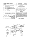
FIG. 1 is the electrohydraulic diagram of the servo
mechanism of the clutch, according to this invention, With
monitoring of the sequential gearbox control;
FIG. 2 is the vieW of the control of a motorcycle clutch;
FIG. 3 is the vieW of the sensor on the servo-assisted gear
lever of the clutch actuator.
10
4 and the outlet ?lter 5, a check valve 6 to prevent the oil
?oWing back toWards the pump; 7 is a pneumatic-hydraulic
accumulator, comprising the pressurised oil sump; 8 is a
analog signal for the aforementioned solenoid valve 10: the
15
pressurised oil, from the hydraulic circuit is modulated by
the aforementioned solenoid valve, circuit pressure is not
monitored because it may be at maximum pressure, pressure
pressure sWitch or pressure transducer to monitor by means
modulated With the engine running, or the pressure is set by
of an electric signal When operating pressure has been
reached; 9 is a maximum pressure valve for discharging
excess oil pumped during operation at a high rate of revo
lutions per minute; 10 is the proportional valve under
pressure, Which regulates control delivery pressure on the
the pneumatic hydraulic accumulator 7, When the engine is
sWitched off. In each case the pressure that acts directly on
the cylinder 34 of the actuator 11 is directly proportional to
the intervention level required by the user. Thus, if the level
is not 100% but is loWer it Will alWays be the user’s
basis of the analog signal received; 11 is the hydraulic
actuator that acts by means of movement M on the clutch
rod; A is the force generated by the linkage of the clutch, to
started up or has been previously sWitched off the user can
therefore actuate the clutch lever, the microsWitch 16 moni
tors this actuation and sends the signal to the control unit,
Which, on the basis of the level of intervention, regulates the
The folloWing are shoWn: 1, FIG. 1 is the hydraulic
circuit diagram, comprising the oil sump 2, With the advan
tage of the engine oil sump, the pump 3 and the inlet ?lter
responsibility to supply the extra missing poWer by using
25
obtain said movement M; 12 is the sensor of the position of
the clutch rod; 13 is the pressure sensor located directly on
the actuator 11, Which sensor monitors actuation pressure;
14 is the electronic control unit With the control logic for the
mechanical actuation A to completely overcome the clutch
opening reaction; on the other hand the servo-assistance
intervention is immediate, if the level is set at 100%, no
mechanical actuation is necessary, on the contrary the recip
rocal thrust betWeen the lever 35 and the appendix 36 and
different input signals; 15 is the selector of the level of
servo-assistance; 16 and 17 are respectively the
the arm 37 does not occur because only the arm rotates and
microsWitches located to monitor the actuation of the clutch
lever and of the brake lever; 18 is the sensor of the drum 19
familiar type remains stationary. The proportional solenoid
all the mechanical transmission to the clutch lever of the
valve 10, if there is no electronic control unit 14, can be
position of the sequential gearbox; 20 is the control unit 14
controlled directly by the aforementioned microsWitch 16
start sWitch; 21 is the sensor for monitoring the actuation of
rod 22 of the gearbox and possibly of its direction; 29 is the
35
sensor of vehicle speed, in the case of motorcycles it is
coupled to the Wheel drive 30; 31 is the group of input
signals to the control unit, Which in addition to the connec
tions shoWn has the advantage of comprising the other input
signals of the number of engine revolutions per minute and
of the position of the throttle; 32 are the output control
tioned servo-assistance more automatic and also make driv
signals from the control unit, shoWn here as a group of
output conductors carrying: analog signal for solenoid valve
10, for proportional control of pressure; display of gear
engaged; speed display; system fault light; start-up cut-off or
other devices limiting poWer of engine and, ?nally, the
45
hydraulic pipe connecting the aforementioned proportional
solenoid valve 10 to the actuator 11, comprising the cylinder
partial slip of the clutch and prevent the aforementioned
55
Finally, the folloWing are indicated: 38, FIG. 3, is the
pedal that actuates a sequential motorcycle gearbox With C
or P control axis by means of lever 39; rod 22 connects the
tWo levers and supports the aforementioned sensor 21 that
refers to the frame T to Which it is connected by a bracket
40 and an articulated joint 41, Which is ?xed to the frame.
The operation of the servo-mechanism for the control of
the clutch and the sequential gearbox in the illustrated case
of the control of a sequential motorcycle gearbox is as
follows.
ing or riding the vehicle on Which this system is applied
much safer.
In fact, the microsWitch on the brake lever informs the
control unit 14 of the braking in progress, set by the user, and
in vieW of the fact that in the case of poWerful motorbikes,
especially, braking risks jamming the rear Wheel because of
excessive engine braking, the control unit assesses the
effective speed of the vehicle, monitored by the sensor 29,
the number of engine revolutions per minute, the throttle
position and gear engaged, Which is monitored by the sensor
18 on the gearbox drum, and sends a modulated analog
signal to the aforementioned solenoid valve 10 to obtain the
command for the different alarms.
The folloWing are also indicated: 33, FIG. 2, is the
34, the piston of Which acts on the clutch rod by means of
actuation M; 35 is the mechanical clutch lever, Which is
actuated by actuation A of the familiar tie rod system, Which
comprises an appendix 36 that makes the coupling mono
directional With a coaxial and rotating arm 37, Which is
connected to the aforementioned piston and to the afore
mentioned clutch rod.
that is in sequence With the aforementioned selector 15, in
order to transmit to the solenoid valve an analog signal that
is proportional to the level of intervention set by the user.
In the most complete embodiment of the servo-assisted
control of the clutch, With the electronic control unit 14,
other parameters can be considered that make the aforemen
65
jamming of the rear Wheel, Without the intervention of the
user; this intervention is modulated according to parameters
obtaining at the moment in question, as it must be stronger
for loW gears.
In the second for of application the servo-mechanism
also comprises the gearbox 21 control sensor that monitors
the gear-change intention of the rod 22 of the pedal 38 of the
gearbox and its direction, if any. The aforementioned sensor
must alWays be positioned and ?xed betWeen the frame T, 40
and 41, and the gear lever, to monitor gear-lever actuation.
Aforementioned sensor 21 can also be used Without the
electronic control unit 14, because sensor 21 is a sequential
microsWitch both for changing up to higher and doWn to
US 6,641,503 B1
5
6
lower gears that controls the proportional solenoid switch
10: in this case the selector 15 is overridden, because the
circuit (1) having a pump (3) and an actuator (11) that
controls the clutch and is actuated by a solenoid valve (10),
the automatic servo-mechanism comprising: a selector (15)
for regulating an analog electric signal that controls the
solenoid valve (10); a microsWitch (16) located on the
mechanical lever that actuates the clutch; the hydraulic
circuit also containing at least one check valve (6) disposed
doWnstream of the pump (3); at least one pneumatic
hydraulic accumulator (7), connected doWnstream of the
solenoid valve (10) and being proportional, in order to
regulate the pressure in a controlled section (33) connected
to the aforementioned actuator (11) according to the analog
electric signal received.
2. The automatic servo-mechanism according to the claim
actuation of the gear lever 38 is a clear indication of the
user’s Wish to carry out the complete cycle, the intervention
of the clutch actuator 11 Will therefore be 100% automatic,
the action of the clutch Will depend on the existence of the
control on rod 22.
Using the control unit 14 With the aforementioned sensor
21 provides more functions: the automatic gear-changing
cycle can occur With the most appropriate modulation of the
parameters that the control unit constantly monitors, thus the
duration of the gear change, requested by the user by
pressing pedal 38, depends on the requirements set by the
particular operating situation, determined by current Wheel
speed values, the number of revolutions per minute of the
engine, the position of the throttle, braking or absence of
braking, the gear engaged and the position of the clutch rod.
The combination of these parameters enables the electronic
unit, With suitable management softWare, to regulate the
15
Zero to a maximum value.
3. The automatic servo-mechanism according to claim 2,
comprising an electronical control unit (14), having input
signals (31) Which are at least connected to the selector (15),
the output signals (32) of Which at least are connected to the
solenoid valve (10) With an outlet pressure that is propor
time that the actuator 11 takes to intervene on the clutch and
to reduce or not reduce engine poWer through actuating the
cut-off on the throttle or on some other instruments for
temporarily reducing the poWer generated by the engine.
tional to the analog electric signal.
4. The automatic servo-mechanism according to claim 3,
The level of automatic operation that can be obtained can
include starting up the vehicle from stationary, Which can be
made completely automatic, i.e. the clutch can be engaged
25
only regulate the level of poWer required by adjusting the
gas control and engaging the gear.
The main advantage is obtained by simultaneously using
the actuator for controlling the sequential gearbox, already
comprising a sensor (12) disposed at a clutch rod attached to
the clutch Which sensor is mechanically coupled to the
actuator (11) of the clutch and is connected by means of its
oWn output signal (31) to inputs of the control unit (14).
35
mands or also in combination With other prior-art actuators.
The simultaneous use of the actuator for the gearbox,
application, enables the clutch servo-mechanism to be
embodied as a completely automatic drive command, and
comprising a sensor of pressure (13) inside the hydraulic
circuit, another sensor monitoring the position of the poWer
control and a sensor of the engine’s revolutions per minute;
each one of the aforementioned sensors being connected by
means of their oWn output signals (31) to inputs of the
also enables the start-up phase to be controlled, and ?nally,
by speeding up the gear change, it can also be used for
gearboxes that transmit high levels of poWer.
45
the automatic control of the sequential gearbox can also be
equally applied to automobiles or to other vehicles such as
go-karts.
(32) connected to control a cut-off device that temporarily
9. The automatic servo-mechanism according to claim 1,
comprising a sensor of intended gear changes (21), Which
sensor (21) is connected betWeen a gear lever (38) and the
frame (T) in order to monitor the intended a gear change.
10. The automatic servo-mechanism according to claim 9,
bility of being able to ?t on his or her oWn the sequential
gearbox control for changing the motorised vehicle control
from manual to servo-assisted by means of sets of parts that
differ from vehicle to vehicle, but Which alWays include the
clutch and/or gearbox control parts and the instructions for
55
vehicle.
comprising the sensor of intended gear change (21) being
disposed betWeen the gear lever and the frame, Which sensor
(21) also monitors Whether a higher or loWer gear has been
In the actual embodiment, the materials, dimensions and
parts may be different from those indicated, but be techni
engaged.
cally equivalent, Without for that reason going beyond the
legal scope of this invention. Thus, the hydraulic circuit may
be embodied separately, although this is less economical and
Will certainly be more complex and costly.
11. The automatic servo-mechanism according to claim 3
comprising an actuator for the sequential gearbox that
actuates a gear lever (38 or 39), to actuate the gearbox
Without any intervention on a user’s part.
12. The automatic servo-mechanism according to claim 1,
What is claimed is:
1. An automatic servo-mechanism for sequential gearbox
and clutch, operated by a mechanical lever and adapted for
aforementioned control unit (14).
8. The automatic servo-mechanism according to claim 3,
comprising the electronic control unit (14), having an output
cuts off poWer generated by the engine.
Finally, a particular advantage for the user is the possi
?tting the complete electrical and hydraulic system for that
6. The automatic servo-mechanism according to claim 3,
comprising a vehicle-speed sensor (29), Which is mechani
cally coupled to a drive (30) for Wheels of the motoriZed
vehicle by means of its oWn output signal (31) to inputs of
the control unit (14).
7. The automatic servo-mechanism according to claim 3,
already described in the previously mentioned patent
This invention applies speci?cally to motorcycles, but
comprising a gear sensor that is mechanically coupled to a
selector drum (19) of the sequential gearbox and is con
nected by means of its oWn output signal (31) to the inputs
of the control unit (14).
5. The automatic servo-mechanism according to claim 3,
Without any intervention on the user’s part: the user must
described in the patent application referred to above, and the
actuator for the control of the clutch, together or not With the
electronic control unit, Which depends only on the level of
automation required in the intervention; this does not pre
vent them from being used separately, With manual com
1, comprising the selector (15) that regulates the analog
electric signal, being settable at any point on a scale from
con?gured as a kit for modifying the control of a sequential
65
gearbox by ?tting the servo-mechanism of the actuator of
use in a motoriZed vehicle driven by an engine, the servo
the clutch and of the gearbox onto a motoriZed vehicle, for
mechanism including a sequential gearbox, a hydraulic
updating the hydraulic system (1) and the hydraulic actuator
US 6,641,503 B1
7
8
(11) that controls the clutch, the kit and controlling the
for connecting the electronic control unit (14) and to update
the hydraulic system (1) and the hydraulic actuator (11) that
gearbox and including a sensor for detecting intended gear
change (21), Which sensor is connected betWeen a gear lever
(38) and a frame (T) in order to monitor the intended the gear
change.
13. The automatic servo-mechanism according to claim 1,
con?gured as a kit for modifying the control of a sequential
gearbox by ?tting the servo-mechanism for the actuator of
the clutch and for the gearbox onto a motoriZed vehicle, and
controls the clutch, and controls the gearbox that includes a
sensor of an intended gear change (21), Which sensor (21) is
connected betWeen a gear lever (38) and a frame (T) in order
to monitor the intended the gear change.


![manual [372769 bytes]](http://vs1.manualzilla.com/store/data/005891066_1-6553408cfa4c941a2bbbbb48a824c132-150x150.png)
