1
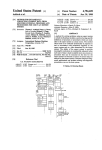
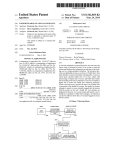
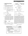
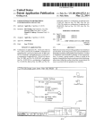
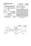
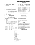
I
United States Patent I19]
[11]
4,236,379
Mueller
[45]
Dec. 2, 1980
'
[54] HEAT PUMP COMPRESSOR CRANKCASE
[56]
References Cited
LOW DIFFERENTIAL TEMPERATURE
DETECTION AND CONTROL SYSTEM
[75]
Inventor:
[73] Assignee:
U. S .
Dale A. Mueller, St. Paul, Minn.
PATEN
T DOCUMENTS
4,004,431
1/ 1977
Hildreth ............................... .. 62/472
4,136,822
1/1979
Felter ................................
236/49
Primtuy Examiner—-William E. Wayner
Attorney’ Agent’ or Firm_R°ger W' Jensen
[57]
ABSTRACI‘
A compressor crankcase low differential temperature
Honeywell Inc., Minneapolis, Minn.
[21] Appl‘ NO‘: 868
_
detection and control system for a reverse-cycle refrig
[22] Flledz
Jan. 4, 1979
eration system for detecting an abnormally low temper
‘
ature crankcase and for controlling the system in re
[51]
[52]
Int. Cl.3 ...................... .. F04B 49/10; F25B 49/00
US. Cl. ...................................... .. 62/126; 62/193;
[58]
Field of Search ............... .. 62/193, 211, 127, 126,
Sponse to such fault detection by inhibiting the opera
tion of the compressor and for providing a fault indica
62/472; 417/32
tiOn.
62/472, 228 R, 229; 417/ 32
I2
K
OUTDOOR
2/
———> /
<-——
f
8 Claims, 2 Drawing Figures
20
OUTDOOR AIR
(TOMS)
REVERSGIG
-—-—>
VALVE
T
CONTROL
cR?g?EAgE
[.43
—AT*I
COMPRESSOR
CONTROLLER
CRANKCASE
i i
TEMPERATURE
"Pr
SENSOR
/ T8’? F42 44
TI-IERRoIIiiiAsTAT
FAULT
INDICATOR I RESET
l7
45
\
63J A
65/ q
/
34
66
(a?-
4
a 4‘E
[~54
/
53
ANALOG To
Mi I.‘
f‘
55
DIGITAL
CONVERTER
'
MICRO PROCESSOR
.
/
56
52
—
Ism)
(T035)
[J40
MULTIPLEXER
i
I44
l~-TCC
COIL
lI
18)
I
35
<—r23
,\~;.->
1*’
~32
Z
INDOOR
Exg?msE
i i
/7
TODA
<—
4— 54
219
TEMSIEENRSAJFIQJRE
F
/$
‘25V
r3’
—> 52
MEANS
EXESAITIGE
con.
10
EXPANSION
L50
_
US. Patent
Dec. 2, 1980'
Sheet 1 Of 2
4,236,379
20
Klz
2/
——>/
OUTDOOR
4-"
f
22
EXPANSION
MEANS
<—-
HEAT
INDOOR
,6
EXCHANGE
COIL
<——- 54
___‘_>
REVERSING
fTl
CONTROL
25
r“ 3/
r IQV
il+
T
T/a)
‘\
r43
LSTEONOSADGF;
ll
CRANKCASE
ll
1*’
TEMPERATURE
"Iv
/7
sENsOR
(TCCS)
/7
LTCC
/ T872
I
THERMOSTAT
(STAT)
I
FAULT
INDICATOR
J ‘
45
RESET
‘ /
65 q
63
62
L-
34
r~ 42 44
ROOM
CONTROLLER
[
2
I
/~/5
COMPRESSOR
“32
COIL
l
CRSQXTCé‘RSE
TEMPERATURE
EXCHANGE
<——/23
fizz-D
VALVE
/4
HEAT
OUTDOOR AIR
TODA
Flo
———> /
66
47 46
35
\
54
4
f" 0
' )
F
MULTIPLEXER
53
—>
ANALOG TO
I
55
f‘
’
D|G|TAL
CONVERTER
MICRO PROCESSOR
‘——/—
56
52
|
V
~
f
\
L50
‘_l
US. Patent
Dec. 2, 1980
4,236,379
Sheet 2 0f 2
FIG. 2
LEGEND
C)
CONNECT TODAS
TO A/ D
I r404
OPERATION
OR
INSTRUCTION
BLOCK
MEASURE
TODA
LOGIC
INSTRUCTION
BLOCK
DIRECTION
OF FLOW
CONNECT TCCS
TO A/D
I [#06
C)
MEASURE
TCC
f- /2/
ENABLE COMPRESSOR
OPERATION
I r122
TURN OFF
FAULT INDICATOR
PAUSE
IS
COMPRESSOR
RUNNING
?
ENTRY POINT
INHIBIT COMPRESSOR
OPERATION
I
[434
TURN ON
FAULT INDICATOR
JUNCTION
1
4,236,379
HEAT PUMP COMPRESSOR CRANKCASE LOW
DIFFERENTIAL TEMPERATURE DETECTION .
AND CONTROL SYSTEM
BACKGROUND OFTHE INVENTION
Heat pumps have been used for many years in the
heating and cooling of buildings; their popularity has
2
ing in the crankcase and thus preventing the above
described damages to the compressor. Thus, a frequent
practice has been, in connection with the installation of
ya new heat pump system, to refrain from starting up the
compressor for a period of time allowing the crankcase
heating means to vaporize any accumulated refrigerant
in the crankcase. However, frequently in practice (ei
ther through carelessness or ignorance) the heat pump
substantially increased in recent times because of the
soaring costs of energy used for heating and cooling.
installer will energize or turn on the compressor imme
Heat pumps become more and more attractive for the
val, and hence cause damage to the compressor. Also, a
crankcase heater failure will cause every compressor
start with potential to dying. Also, an extended heater
power loss could cause foaming.
function of heating and cooling of buildings because of
their operating ef?ciency; ‘i.e., their cost effectiveness.
However, heat pumps do have some problems; one of
these is connected with the fact that in many systems
the refrigerant in the line may, during times that the
system is at rest, settle in the crankcase of the compres
sor. This is because, in the system “OFF” condition, the
refrigerant in the reverse cycle heat pump will tend to
condense at the location which has the lowest tempera
ture in the system. The “coldest” location typically is in
the outdoor unit (where the compressor is usually lo
cated) when a system is in the heating mode, because
the outdoors is generally much cooler than the indoors
for this case. Thus, the refrigerant may settle, i.e., con
dense in the crankcase of the compressor; the refriger
ant will continue condensing at such coldest location
until a point of equilibrium is reached, i.e., an equilib
rium of liquid and gaseous refrigerant at the vapor pres
sure corresponding to the temperature at such coldest
location. It has been recognized heretofore that it is
important not to start up the compressor when the re
frigerant has settled in the compressor crankcase as it is
known that the refrigerant in the crankcase will tend to
mix with the compressor lubricating oil therein. It is
likely that this mixture is present at equilibrium because
the mixture causes a reduction in the total volume of
diately; i.e., without waiting for the warming up inter
It is an object of our invention to provide a new and
effective system for detecting compressor crankcase
low differential temperatures and for inhibiting the
operation of the heat pump compressor until such time
as‘the crankcase temperature increases above the out
door air temperature to a safe level.
SUMMARY OF THE INVENTION
The present invention is a compressor crankcase low
differential temperature detection and control system
fora reverse cycle refrigeration system comprising the
usual refrigerant compression means, including crank
case heating means, indoor and outdoor coils, refriger
ant conduit means connecting the compression means
and the coils, and refrigerant compression control
means. In particular, the control system comprises out’
door air temperature sensing means having an output
indicative of outdoor air temperature, crankcase tem
perature sensing means having an output indicative of
the crankcase temperature, enclosure (e.g., building)
temperature sensing means having an output indicative
of a demand for either heating or cooling of the enclo
liquid as compared with a system containing separate
pools of oil and refrigerant, thus enabling more refriger‘,
sure, fault indicator means, and controller means. The
Thereafter, when the compressor is started, if there is
outputs thereof. The controller means further has a
controller means has operative connections to the three
recited temperature sensing means so as to receive the
ant to condense at the same equilibrium vapor pressure. 40
refrigerant in the crankcase oil, then such refrigerant
will tend to boil due to the low pressure on the suction
side of the compressor (where the crankcase is located)
and when this happens the refrigerant will agitate the
oil causing the oil to foam; this foam then is apt to be
carried into the intake of the compressor and thereafter
be pumped out by the compressor into the refrigerant
lines. When this happens, the oil may be pumped out of
the crankcase, thus causing the compressor to run with 50
out lubricant until the oil migrates back having trav
elled throughout the complete refrigeration system; i.e.,
back through the refrigerant tubes and into the crank
case. Such running without lubrication may cause se~
vere wear and overheating of the compressor, thus
shortening the life of the compressor and causing ex
pense, inconvenience and discomfort. Another related
problem is that the oil refrigerant foam mixture is not as
compressible as refrigerant vapor; this can cause “slug
ging” and eventual damage to the valves of the com
pressor.
.
All of the foregoing has heretofore been recognized
and various prior art techniques have been proposed for
dealing with the problem. Thus, at this time, many heat
circuit connect-disconnect means which selectively
interconnects the enclosure temperature sensing means
to the refrigerant compression control means. The con
troller functions so that it is effective to inhibit the com
pression means from operating if both the outdoor air
temperature is below a predetermined value and if the
value of the crankcase temperature minus the outdoor
air temperature is greater than a preselected amount.
BRIEF DESCRIPTION OF THE DRAWINGS
FIG. 1 is a block diagram of a compressor crankcase
low temperature detection and control system for a
reverse cycle refrigeration system embodying the pres
ent invention; and
.FIG..2 is a ?ow chart for the control of the apparatus
depicted in FIG. 1.
DESCRIPTION OF THE PREFERRED
EMBODIMENT
Referring to FIG. 1, the reverse cycle refrigeration
system comprises an indoor heat exchange coil 10, an
outdoor heat exchange coil 12, a refrigerant compres
sion means or compressor 14, and a compressor control
pump compressors have some means for heating the 65 ler 15 receiving energization from an appropriate
source 17 of electrical energy. Also associated with the
crankcase of the compressor so that the crankcase will
compressor 14 is a crankcase heater 19 receiving energi
not be the lowest temperature point in the heat pump
zation from source 17. Refrigerant conduit means are
system; thus preventing the refrigerant from condens
3
4,236,379
provided for interconnecting the coils and the compres
sor, the conduit means including the usual reversing
valve 16 having a controller 18, an expansion means 20
and appropriate interconnecting piping 21-26. The sys
tem above-described is representative of prior art sys
4
indicator 63 and a fault reset means 65, i.e., a switch,
both of which will be described in further detail below.
For convenience, elements 42, 63 and 65 as above de
scribed are shown adjacent to one another in FIG. 1, all
having the common designator T872.
tems such as that shown in US. Pat No. 3,170,304. As is
Further, Honeywell Inc. platinum ?lm resistance
well known, such systems function whenever the build
ing thermostat is calling for heating or cooling to cause
compressor 14 to operate. If heating is being demanded
then the compressed hot refrigerant from the compres
type temperature sensors models C800A and C800D
may be used for TODAS 31 and TCCS 34 respectively.
sor 14 will be routed through the reversing valve 16
toward the indoor heat exchange coil 10 where its heat
is given up to heat the indoor air. Conversely, if cooling
of the building is being demanded, then the hot refriger
ant from the compressor is routed through the reversing
Also, a‘ Carrier Corporation heat pump comprising
outdoor unit model N0. 38CQ033300 and indoor unit
model No. 40AQ036300JR may be used for the basic
heat pump unit depicted in FIG. 1; i.e., components 10,
12, 14, 15, 16 and 19.
'
As indicated above, multiplexer 40 has applied
thereto at 32 and 35 analog signals representative of
valve to the outdoor heat exchange coil 12 where the
refrigerant is cooled for subsequent use indoors to cool
TODA and TCC respectively. The function of the
the building.
input signals in analog form to the output 53 thereof,
multiplexer 40 is to supply one or the other of the two
depending upon the nature of the control signal being
The compressor crankcase low temperature detec
tion and control system as depicted in FIG. 1 comprises 20 applied to the multiplexer 40 via a lead 52 from the
microprocessor 50; i.e., the microprocessor provides a
an outdoor air temperature sensing means 31 (hereinaf
control for the multiplexer 40 to select which of the two
ter sometimes referred to as “TODAS”) having an
input signals is applied to output 53. Output 53 is applied
output 32 on which is an output signal indicative of the
as the input to a standard analog-to-digital converter 54
outdoor air temperature (hereinafter sometimes re
ferred to as “TODA”). TODA on output 32 comprises 25 (herein sometimes referred to as “A/D”) having an
output 55 connected as a second input to the micro
one of two separate inputs to a multiplexer 40 to be
processor 50 and also having an input 56 for receiving
described in more detail below. The detection and con
controlling instructions from the microprocessor 50.
trol system further comprises a crankcase temperature
The output from analog-to-digital converter 54 at out
sensing means 34 (hereinafter sometimes referred to as
put 55 is a signal in digital form indicative of the analog
“TCCS”) having an output 35 on which is available an
output signal indicative of the crankcase temperature of
the compressor, this temperature hereinafter sometimes
signal applied to input 53. The microprocessor 50 has an
output 62 connected to fault indicator 63. The apparatus
being referred to as “TCC”, such TCC signal on 35
further includes the above-mentioned fault reset means
65 having an output 66 which constitutes a third input
detection and control system further includes a room 35 to the microprocessor 50.
A suitable microprocessor that may be used in the
thermostat 42 (hereinafter sometimes referred to as
present invention as a component of the system de
“STAT”) which responds to the temperature of a room
picted in FIG. 1 is the Intel Corporation Model 8049; a
or space in a building or the like, the temperature of
comprising the second input to multiplexer 40. The
suitable representative analog-to-digital converter for
which is to be controlled by the reverse cycle refrigera
tion system. Room thermostat 42 is depicted as having 40 use to provide the function of block 54 in FIG. 1 is the
Texas Instrument Inc. Model TL505C (see TI Bulletin
a first output 43 connected to the control 18 for the
DLS 12580); and an appropriate multiplexer is the Mo
reversing valve 16. A second output 44 of STAT 42 is
torola Inc. Model MCl405lBP.
connected to a microprocessor 50 and also (through a
It will be understood by those skilled in the art that
set of contacts 46 and a connection means 45) to the
controller 15 of compressor 14. Contacts 46 are con 45 the functional interconnections depicted in FIG. 1 are
representative of one or more electrical wires or pipes,
tained within a subsection 47 of the microprocessor 50
as the case may be, as dictated by the specific equipment
and both 47 and 50 will be described in more detail
used.
below.
A Honeywell Inc. Model T872 heating-cooling ther
The detailed operation of the detection and control
mostat may be used for the room thermostat 42 depicted 50 system of FIG. 1 may be more speci?cally understood
in FIG. 1, the Model T872 being of the bimetal operated
mercury switch type including switch means for pro
viding the heating-cooling control signals and also for
controlling a plurality of auxiliary heating means. As
will be understood, whenever STAT 42 calls for either
heating or cooling of the controlled space, then a con
by reference to the flowchart depicted in FIG. 2 where
reference numeral 101 designates an entry point “sys
tem power applied” re?ecting the status of the heat
pump being powered up; i.e., power 17 being applied to
compressor controller 15 and crankcase heater 19 and
appropriate energization being applied to any other of
the depicted apparatus requiring same. The system then
?ows via junction 102 to instruction block 103 “connect
TODAS to A/D”; this being indicative of the TODA
via control 18 the reversing valve 16 to the proper
orientation for either heating or cooling of the building 60 signal on output 32 being applied via multiplexer 40 to
the analog-to-digital (A/D) converter 54. The flow
and at 44 to advise microprocessor 50 that heating or
from 103 is to operation or instruction block 104 “mea
cooling has been called for by STAT 42. The control
sure TODA” the flow from which is to instruction
signal at 44 is transmitted through the normally closed
trol signal is effectively supplied on outputs 43 and 44
thereof, the control signal at 43 functioning to position
contacts 46 and connection 45 to control the compres
block 105 “connect TCCS to A/D”, the flow from
sor 14 from a rest or “off’ condition to an operating or 65 which is to instruction block 106 “measure TCC”.
“on” condition and is also applied to microprocessor 50
Thus, instructions 103, 104, 105, and 106 collectively
to indicate a demand for compressor 14 operation. The
Honeywell Model T872 STAT further includes a fault
TCC temperatures, utilizing the aforedescribed multi
are associated with the measurement of the TODA and
5
4,236,379
6
s/operations. The ?rst is the inhibiting of the compres
sor operation; block 133 is indicative of microprocessor
50 operating to open’ contacts 46 to preventSTAT 42
plexer 40, analog-to-digital converter 54 and micro
processor 50.
The flow from block 106 is to a logic instruction 107
“TODA>TREF,?” having a yes response 108 and a no
response 109. TREF, is a reference temperature or set
commanding operationof compressor 14. The second
operation resulting'from a'no response 131 is the actua
tion of fault indicator163 (by block 134). The closing of
the loop by 135 back" to 132 permits the test’ to be re
peated; as long as the response from logic instruction
point with respect to which TODA is compared; and is
selected to be a temperature high enough so that refrig
erant would not normally condense in the crankcase or
in the outdoor coil; i.e., the refrigerant would stay in
130 continues to be a “no” response at 131,‘ then the
gaseous form in the crankcase and in the outdoor coil,
and instead the refrigerant would condense in the
compressor operation will be inhibited and the fault
indicator 63 will be actuated. Knowledgeable personnel
notingthat the fault indicator 63 is actuated may take
cooler indoor coil. A representative TREE would be 80°
F. If TODA is greater than TREE then there is not
likely to be a problem with refrigerant mixing with the
oil of the compressor crankcase; hence, the yes response
108 ?ows via a junction 120 to an instruction block 121
“enable compressor operation”, the flow from which is
to instruction block 122 “turn off fault indicator”, the
flow from which is to instruction block 123 “pause”, the
flow from which is via a junction 124 to a logic instruc
tion block 125 “is compressor running?” having a yes
corrective steps, one of which is to permit the passage
of enough time to permit the crankcase heater to func
tion. In due course the crankcase temperature should
increase to the point where the output from 130 will be
a yes response 132 to flow through 120 to block 121 et
seq so as to successively enable compressor operation
and to turn off the fault indicator 63. On the other hand,
20 a persistent fault indication at fault indicator 63 would
response 126 and a no response 127. Thus, a yes re
necessitate further investigation’ by appropriate servic
ing personnel to determine and correct the cause of the
fault.
sponse at 108 from logic block 107 is representative of
As indicated above, an Intel Model 8049 micro
an absence of any possible problem and hence is com—
patible with normal operation vis: block 121 designates 25 processor may be used to practice the subject invention;
as an assistance reference may be made to “INTELR
the enabling of compressor operation and 122 is repre
MCS-48TM Family of Single Chip Microcomputer
sentative of the fault indicator 63 being turned off. The
s—User’s Manual”, a 1978 copyrighted manual of the
block 123 “pause” is indicative of the periodic recyl
Intel Corporation, Santa Clara, California 95051. As a
cling of the system, i.e., the periodic functioning of the
further assistance, Appendix A hereto and forming a
system to determine whether or not there is a problem
part hereof, comprises a table of machine readable in
with the temperature of the crankcase of the compres
struction for controlling the aforesaid Intel Model 8049
sor, a frequency of 120 cycles per hour having been
microprocessor for use in the present invention.
found satisfactory. Flow from 123 via 124 into logic
block 125 “is compressor running?” results in either a
While we have described a preferred embodiment of
yes or a no response; a yes response 126 ?ows back to 35 our invention, it will be understood that the invention is
junction 124 and thence to 125 in a closed loop fashion;
however, a no response 127 (indicating that the com
pressor is not running) causes flow back to junction 102
so that the test at logic instruction block 107 may be
repeated.
~When TODA is not greater than TREE, then the no
limited only by the scope of the following claims:
I claim:
1. A compressor crankcase low differential tempera
ture detection and control system (hereinafter “control
system”) for a reverse cycle refrigeration system (here
inafter “system”) for heating and cooling an enclosure
response 109 from logic instruction 107 causes flow to a
wherein said system comprises refrigerant compression
logic instruction block 130 “TCC minus TODA is
means including crankcase heating means, refrigerant
greater than ATMIN?” having a no response 131 and a
compression control means, an indoor coil, an outdoor
yes response 132. Logic instruction block 130 thus pro 45 coil, and refrigerant conduit means connecting said
compression means and said coils, said control system
vides a comparison between (i) AT, i.e., the difference
comprising:
in magnitude between the compressor crankcase tem
outdoor air temperature sensing means (hereinafter
perature TCC and the outdoor air temperature TODA
“TODAS”) having an output indicative of outdoor
and (ii) ATMIN where ATMIN is a predetermined value.
air temperature (hereinafter “TODA”);
If AT is greater than ATMIN, then this is indicative of a 50
safe operating condition, i.e., the crankcase temperature
being sufficiently greater than the outdoor air tempera
ture so as to con?rm that the crankcase heating means
has been operated a suf?cient length of time so as to boil
away any refrigerant that otherwise might be comin 55
gled with the oil in the crankcase. Such “safe operating”
condition causes a yes response 132 to flow via junction
120 to 121 et seq. A value of ATMIN of 10° F. has been
found satisfactory for TODA less than 55° F. and 6° F.
for TODA greater than 55° F. However, if the crank 60
case temperature is not high enough, then the no re
sponse 131 from 130 will cause flow to an instruction
bloc 133 “inhibit compressor operation”, the flow from
which is back to junction 10 described above via a con
nection 135. Thus, if the crankcase temperature is too 65
low in comparison to the outdoor air temperature, this
is indicative of a potential severe problem as described
aforesaid; thus, the no response at 131 causes two event
compressor crankcase temperature sensing means ,
(hereinafter “TCCS”) having an output indicative
of the temperature (hereinafter “TCC”) of the
crankcase of said refrigerant compression means;
enclosure temperature sensing means (hereinafter
“STAT”) having an output indicative of a demand
for heating or cooling of the enclosure; and
controller means having operative connections to
said TODAS, TCCS, and STAT so as to receive
the outputs thereof, said controller means includ
ing circuit connect-disconnect means selectively
interconnecting said STAT output to said refriger
ant compression control means whereby, when
said STAT output is connected thereto, said com
pression means is enabled to operate in response to
a demand from said STAT for heating or cooling
and, when said STAT output is disconnected there
from, said compression means is inhibited from
7
4,236,379
8
wherein said system comprises refrigerant compression
operating, said controller means being effective to
inhibit said compression means from operating
whenever the value of TCC minus TODA is less
than a preselected amount, and said controller
means including crankcase heating means, refrigerant
compression control means, an indoor coil, an outdoor
coil, and refrigerant conduit means connecting said
compression means and said coils, said control system
means being further characterized by permitting
operation of said compression means whenever
comprising:
TODA is greater than a predetermined value.
‘ outdoor air temperature sensing means (hereinafter
2. Apparatus of claim 1 further characterized by said
“TODAS”) having an output indicative of outdoor
preselected amount being 10° Fahrenheit when TODA 1
air temperature (hereinafter “TODA”);
is less than 55° F. and 6° F. when TODA is greater than 10
55° F.
3. Apparatus of claim 1 further characterized by (i)
said control system including fault indicator means and
(ii) said fault indicator means being actuated upon, as
aforesaid, said controller means inhibiting said compres
sion means from operating.
4. Apparatus as described in claim 3 further charac
compressor crankcase temperature sensing means
(hereinafter “TCCS”) having an output indicative
of the temperature (hereinafter “TCC”) of the
crankcase of said refrigerant compression means;
enclosure temperature sensing means (hereinafter
“STAT”) having an output indicative of a demand
for heating or cooling of the enclosure; and
controller means having operative connections to
terized by said controller means permitting operation of
said compression means whenever TODA is greater
than a predetermined value.
5. Apparatus of claim 1 further characterized by said
preselected amount being in the range of 6 to 15 degress
Fahrenheit.
6. Apparatus of claim 4 further characterized by said
preselected amount being in the range of 6 to 15 degrees 25
Fahrenheit.
7. Apparatus of claim 6 further characterized by said
predetermined value being in the range of 80° F.il0°
said TODAS, TCCS, and STAT so as to receive
the outputs thereof, said controller means includ
ing circuit connect-disconnect means selectively
interconnecting said STAT output to said refriger
ant compression control means whereby, when
said STAT output is connected thereto, said com
pression means is enabled to operate and, when said
STAT output is disconnected therefrom, said com
pression means is inhibited from operating, said
controller means being effective to inhibit said
compression means from operating unless one of
the following conditions is satisfied:
(1) TODA is above a predetermined value; or
(2) the value of TCC minus TODA is greater than
F.
8. Compressor crankcase low differential temperature
detection and control system (hereinafter “control sys~
tem”) for a reverse cycle refrigeration system (hereinaf
ter “system”) for heating and cooling an enclosure
a preselected amount.
)3
35
45
55
65
*
*
*
Ill