1
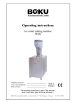
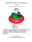
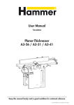
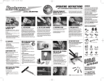
COMPONENT CHECKLIST
2. Place the blade of a slot
screwdriver under the float arm
Extra care is taken to ensure that all Racetronix kits are tested
as shown in figure 'B1'. Gently
and packaged properly. Please use the photo and checklist below
rotate the screwdriver until the
to familiarize yourself with the kit components and to ensure that
float arm pops straight up and
you are not missing any of the pieces.
out of the plastic level sender.
The F98 fuel pump assembly is comprised of:
Place the arm in a safe place until
your installation is complete so
[ ] - Fuel pump assembly
[ ] - Hex key
that it does not get bent.
[ ] - Fuel sock adapter
[ ] - Paperclip
[ ] - In-tank wiring harness
B1
[ ] - Hose clamp
A
CAUTION!
A bent float arm will give false
fuel level readings on your
dash gauge.
B2
3. Place the blade of a slot
C
screwdriver under the fuel sock
nipple as shown in figure 'C'.
1. Cover the ends of the metal tubes coming out of the sending Gently rotate the screwdriver
unit with electrical tape to protect them from getting
until the fuel sock nipple starts
scratched. If the push-lock ends become damaged they will
to slide off. Place the slot
leak when inserted back into their female mates.
screwdriver on the opposite side
Bulkhead
of the fuel sock nipple and do the same.
Vapor
Connector
Once the fuel sock nipple is about half
Pressure
way off the fuel pump's inlet, you
Sensor
Vent
may gently pull the sock off by
pulling straight down with a
Bulkhead Jack
slight rotating motion. If the
sock does not come off easily
Regulator
use the slot screwdriver to further
loosen the nipple.
PATENT
PENDING
8. Place the blade of a slot
screwdriver under the ground
terminal as shown in figure 'H' to
release its spring lock. While
holding the lock in the released
position, pull up on the terminal
to disconnect it from the spine of
the sending unit as shown in
figure 'H'.
9. Place the blade of a slot
screwdriver under the orange lock
as shown in figure 'I' to gently
pry it out. Sometimes you may
have to work both sides of the
orange lock in order for it to release
itself from the black connector.
C2
Feed
Line
Level Sender
Return Line
Pump
Module
Float Arm
Float
Filter Sock
REQUIRED TOOLS
The following hand tools are required to remove the
factory fuel pump module and replace it with the new
Racetronix unit:
[
[
[
[
] - Utility or X-Acto knife
] - 3/16" Slot screwdriver - medium size blade
] - 1/4" Nutdriver or socket with handle (optional)
] - 5/16" Nutdriver or socket with handle (optional)
4. With a firm grip separate the
fuel sock from the return line as
shown in figure 'D'. This
requires a moderate amount of
force. You may leave the sock
attached to the return line during
the installation but we have found it
easier with it out of the way.
5. Release the connector's two
adjacent locking ears by lifting
them away from the socket
body as shown in figure 'E'.
Once both ears are lifted gently
pull back on the connector to
unplug it. If you find the locking
ears too hard to grasp with your
fingers, a slot screwdriver can be
used to gently pry them back.
6. Using a utility knife, or sidecutters gently make a slit or nick
in the plastic outlet hose as
shown in figure 'F'. Do not cut
through the hose which will
score the metal tube and
prevent a proper seal with the
F
new tube. Pull the hose off the
steel line as it is no longer required and is not reusable. Sometimes
fuel trapped inside the pump will leak out once the hose is cut.
Keep a shop rag handy to absorb any remaining fuel.
7. With a firm grip separate the
G.M. fuel pump assembly from
the spine of the sending unit by
pulling in opposite directions as
shown in figure 'G'. Lift the fuel
pump assembly out and set it
G
aside. The fuel pump assembly
may contain fuel so be sure to
place it in a safe container in
order to prevent a fuel spill.
D
E
10. Gently pull back on the black
connector's body while using the
blade of a slot screwdriver to
depress its locking tab as shown
in figure 'J'. While grasping the
J
connector's body a gentle rocking
motion may be required to get it
to slide off. Do not pull by the
wires. If the connector does not
move, make sure that you are
applying enough force with the
screwdriver on the black locking
tab to keep it down. This will
allow it to pass under the lock
hole in the metal bracket. Once the lock is released the black
connector will slide easily off as shown in figure 'J'.
11. Using the supplied hex key
remove the two bottom fuel pump
module mounting dowels as shown
in figure 'K'. Make sure that the
hex key is inserted all the way so
you do not strip the cap screws.
K
12. Bending the FSU's
spine to remove the old
fuel pump module causes
excessive clearance
L
between the upper and
lower sets of rubber
bumpers. Tension is required to properly hold the fuel
pump module in place. To retension the module, gently bend the
bottom 'L' portion up as shown in figure 'L' very slightly. About 3/
8" inch in recovered distance is required for proper tension. If you
are unsure of how much to bend the spine, do so in small increments. The tension can be checked in the next few steps and if required,
you can always apply more. Do not over tension the spine!
13. Slide the Racetronix fuel pump module into the two
upper rubber bumpers as shown in figure 'M'.
H
I
14. Slide a mounting dowel
on to a lower rubber bumper.
M
Gently pull back the fuel
pump module and place its
edge onto the mounting
dowel's edge. There should
be tension on the dowel.
(Return to step 13 for retensioning procedure if required)
Align the mounting dowel over the threaded hole in the fuel
pump module. Replace the cap screw holding the mounting dowel
with the supplied hex key as shown in figure 'N'.
Make sure the hex key is fully inserted into the cap screw
before tightening so that you do not strip the head. Make
sure the screw turns freely while using the long end of the
hex key so that you do not cross-thread the cap screw. Use
the short end of the hex key to tighten the cap screw once it
is all the way in. Make sure the screw is tight as this must
not come loose once in the tank.
15. Repeat step 14 for the second bottom dowel.
16. Remove the gray terminal
lock from the black bulkhead
connector by pressing down and
up on its locking ears located on
both sides of the connector as
shown in figure 'N'.
N
17. Release the locking tang on the violet level sender terminals
inside the black bulkhead connector by inserting the supplied paper
clip into release channel 'B' and 'D' as shown in figure 'O'. Make
sure the paper clip is fully bottomed in the
channel and then remove it. Give a
O
gentle tug on each violet wire and
they should slide out from the
connector body. If they do not come
out easily re-insert the paper clip and
try again. Do not try to force the
terminals out of their cavities as
you may damage them!
18. Using a small utility blade gently
bend the locking tangs of each violet
P
wire's terminal slightly up as shown in
figure 'P'. If the terminal is positioned as shown in figure 'P' the tang
should point towards two o'clock.
This will help the terminal achieve a
positive lock when it is re-inserted.
19. Insert one violet wire's
terminal into marked channel 'B' C
B
of the new Racetronix
bulkhead connector and the other
into marked channel 'D' as
shown in figure 'Q'. The
terminal tang points towards
Q
the connector's lock. The
D
E
terminal should make a 'click'
once inserted indicating that its
tang has locked into place properly. Gently tug on the violet wires
to confirm a positive lock. If a terminal slips out of the cavity
inspect it for contamination or deformation. If all looks OK repeat
steps 18 and 19. Cavity 'E' black wire is pump - and cavity 'C'
gray wire is pump +.
DOUBLE CHECK THE 4 BULKHEAD AND 2 PUMP TERMINAL POSITIONS TO PREVENT PERMANENT PUMP AND
LEVEL SENDER DAMAGE. ALWAYS DOUBLE CHECK
FACTORY AND INSTALLER CONNECTIONS!
20. Insert the new gray terminal lock so that both ears lock into place
on either side of the black connector as shown in figure 'R1'.
23. Slide the ground terminal
with the two black wires
attached onto the grounding
point as shown in figure 'S'.
Make sure the connector is
seated and locked by gently
S
pulling it back. It should not
come off if the locking dimple has been seated in its hole as shown
in figure 'S'.
24. Place the supplied
small crimp clamp onto
the steel feed line. Slide the
flex fuel line from the
Racetronix pump
assembly onto the steel
feed line until the end
reaches the top bump as
shown in figure 'T'. This
may require a bit of force
as it is a tight fit.
T
25. Slide the crimp clamp over the flex fuel line and position it
between the two bumps on the metal fuel feed-line as shown in
figure 'T'. Using a pair of side cutters or fence pliers crimp the
clamp as shown in figure 'U1' and 'U2'. Do not use excessive
force which may cut through the crimp clamp.
U2
U1
V
FPA-002A
U3
29. Using a supplied tie secure the fuel return tube attached to the
regulator onto the left side spine of the sender as shown in figure
'V1'. Cut the excess tie flush as shown in figure 'V2'.
27. Place the small lock ring on
the end of a nut-driver or socket
with its flared end inwards
towards the socket as shown in
figure 'U1'.
30. If the tank seal o-ring was
removed to aid in the assembly
slide it back to the top of the
sending unit. Make sure the tank
seal o-ring tank has the thin
portion of its body pointing
down towards the fuel filter sock
as shown in figure 'W'.
1998 cars with metal fuel tanks only
W
31. Lock the float arm into the
X
level sender by pressing firmly
and straight in so that the arm
snaps into the plastic locks as
shown in figure 'X'. Do not
place bending force on the level
sensor arm otherwise damage will
occur. Apply direct force to the arm only in order to lock it into place.
Inspect the gas tank for contamination (i.e. sand rust). A brown / black dirty factory
filter sock indicates potential trouble / premature pump failure. Even a new F-98 LS1
metal tank can contain rust as gas station tanks contain all types of contaminants.
U1
1
998 L
S1 F
-Body
1998
LS1
F-Body
High-Performance
Fuel Pump Assembly
Installation Manual
V2
CAUTIONARY NOTES
Run through the entire installation procedure to make sure nothing has been
overlooked before installing the sender back into the tank. Double check the
electrical connections to make sure the correct wires are in the proper cavities.
22. Replace the orange connector lock as shown in figure 'R2'.
Make sure the orange lock is inserted all the way. This lock
prevents the connector from backing out due to vibration.
R2
U2
V1
26. Place the filter sock on the
bottom of the pump making sure
it is fully seated as shown in
21. Inspect the male bulkhead connector terminals for corrosion and
figure 'V'.
clean them with fine sandpaper (400+) or steel wool if required.
Plug the black bulkhead connector in until it locks into place as
shown in figure 'R1'.
R1
28. While holding the pump assembly standing up, press the small
lock ring onto the pump's bottom locating nipple to lock the filter
sock into place as shown in figure 'U2'. BE VERY CAREFUL
NOT TO DROP & LOSE THE LOCK RING.
Fill the tank with at least 10 gallons of fuel and let stand 10 minutes before
attempting to run the pump.
CAUTION
This manual is intended to be used in conjunction with the G.M.
factory service manual. Please consult the G.M. manual for
precautionary notes, torque specs and items that may be beyond
the scope of this manual.
This product is intended to be installed by a qualified automotive
service technician. Review this entire manual before starting
installation. Proper safety precautions must be implemented when
working with gasoline.
Always disconnect the negative battery cable before commencing
electrical work on a vehicle. Observe factory vehicle jacking /
lifting recommendations and safety precautions.
Improper installation, use or modification of this product voids all
warranties.
Unauthorized duplication and distribution of this manual is
prohibited by law.
Do not use gas that has been open or sitting for long periods of time. (i.e. winter storage)
as it can contain water which will damage the pump.
For support please contact your dealer or [email protected]
Rev 1.03
WWW.RA
CETR
ONIX.CO
M
.RACETR
CETRONIX.CO
ONIX.COM
Aug 2014