1
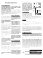
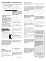
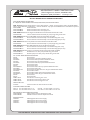
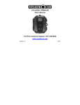
RT-3000 Series NEMA 4X TYPE 4X ENCLOSURE WATERTIGHT CORROSION RESISTANT DUCT SMOKE DETECTORS INSTALLATION AND MAINTENANCE INSTRUCTIONS RT-3000-N Ionization Type, 4-Wire Duct Smoke Detector RT-3000-P Photoelectric Type, 4-Wire Duct Smoke Detector NOTICE: The information contained in this document is the most current available at the time of shipment of accompanying product, and is subject to change without notice. Future references should always be made to the most current revision of this document. The information contained in all this document should be considered before installing or using the product. Any example applications shown are subject to the most current enforced local/national codes, standards, approvals, certifications, and/or the authority having jurisdiction. All of these resources, as well as the specific manufacturer of any shown or mentioned related equipment, should be consulted prior to any implementation. For further information or assistance concerning this product, contact Air Products and Controls Inc. Air Products and Controls Inc. reserves the right to change any and all documentation without notice. © Air Products and Controls Inc. 2009 A COPY OF THESE INSTRUCTIONS SHOULD BE LEFT WITH THE EQUIPMENT UNTIL INSTALLATION BY ALL TRADES IS FULLY COMPLETE. FOLLOWING FINAL INSPECTION, A COPY SHOULD BE LEFT WITH THE OWNER/USER. for technical support call toll free 888-332-2241 or 248-332-3900 AIR PRODUCTS AND CONTROLS INSTALLATION & MAINTENANCE INSTRUCTIONS FOR RT-3000 SERIES DUCT SMOKE DETECTORS RT-3000 Duct Smoke Detectors AT-A-GLANCE MOdel Number: NEMA 4X Type 4X Enclosure - Watertight, Corrosion Resistant RT-3000-N RT-3000-P You in Control RT-3000-N Ionization Type, 4-Wire DSD RT-3000-P Photoelectric Type, 4-Wire DSD Product overview PRODUCT APPLICATION This detector is equipped with a cover RT-3000 Series duct smoke detectors provide early detection of smoke and products of combustion present in air moving through an HVAC duct supply, return, or both in commercial, industrial, and residential applications. These devices are designed to prevent the recirculation of smoke in areas by the air handling system’s fans and blowers. Complete systems may be shut down in the event of smoke detection NOTE: For the correct installation of a duct smoke unit, please refer to the NFPA 72 (National Fire Alarm Code), NFPA 90A (Standard for Installation of Air Conditioning and Ventilation Systems), NFPA 92A (Recommended Practice for Smoke Control Systems.), NFPA 5000 (Building Construction and Safety Code), IMC (International Mechanical Code), IFC (International Fire Code) and NEC (National Electric Code). Inst aPD0344 A090630 122.6mA 125.2mA 251.0mA 401.5mA 45.0mA 48.2mA 100.0mA 304.4mA 115VAC 31.0mA 47.2mA 50.0mA 91.2mA 230VAC 17.0mA 29.2mA 29.0mA 50.6mA Audible and visual alarm indicators, remote status indicators, and remote reset/test switches can be accommodated by the RT-3000 Series duct units by connecting to the proper terminals as described on page 10. These terminals are not supervised. The remote pilot (green) LED will be permanently illuminated when connected to the proper terminals as long as the following conditions are met: • input power is present • detector head is present • unit cover is in place with latch in closed position With Accessories 24VAC REMOTE ACCESSORIES The operating principle of a duct detector is based on the Venturi effect. Two tubes extend into the HVAC duct. Air flowing through the duct is forced into the air intake (inlet) tube via the air intake holes, (facing the airflow) and passes over the detector head. The air will be drawn out via the exhaust tube back into the HVAC duct. (A 7" exhaust tube is provided in the installation kit.) When the concentration of smoke particles suspended in the air stream reach the alarm threshold of the detector head, the unit will go into alarm. The duct smoke detector units are designed to operate in duct widths from 6" to 10' wide with 1 alarm current 24VDC an air velocity between 100 to 4,000 feet per minute. To verify correct installation, the pressure differential between the sampling (high pressure side) and exhaust (low pressure side) tubes should be measured using a Magnehelic pressure gauge or equivalent. An acceptable reading is between 0.01 and 1.8 inches of water. To minimize the impact of air turbulence and stratification on performance, a duct smoke detector should be located as far as possible downstream from any obstruction (i.e. deflector plates, elbows, dampers, etc.). In all situations, confirmation of velocity and pressure differential within specifications is required. SAMPLING TUBES The RT-3000 Series duct smoke detector is fitted with a mounting base that will accept an ionization smoke detector head model 55000-225 or photoelectric smoke detector head model 55000-328. The duct unit provides two sets of form “C” alarm contacts, one form “A” alarm contact, one form “B” trouble contact and one form “C” trouble contact. The trouble contacts supervise the presence of the input power, removal of the detector cover and the removal of the smoke detector head. STANDBY current with Accessories The RT-3000 cover seats firmly against a high-performance rubber gasket. To avoid accidental damage to the gasket: When removing the cover pull/lift uniformly on the corner tabs. When replacing the cover, be sure the stainless steel cover latch is in its upright position before properly seating the cover straight onto the base. Then fully depress the cover latch. PRODUCT DESCRIPTION Power This detector is not intended for open area protection nor should it be used for early warning detection or replace a regular fire detection system. 55000-225 55000-328 power requirements: removal switch (COVER REMOVAL on PCB) that instantly provides a trouble condition upon lifting lever while not in Maintenance Mode. For all testing and inspection with the cover removed, the maintenance switch (designated as MAINT on PCB) may be momentarily depressed to simulate standard “pilot” operation for a predetermined time of 3 minutes. ALL TROUBLE CONTACTS ARE SHOWN / labeled IN THE ENERGIZED CONDITION. The trouble contacts will not operate in the event of a smoke alarm. The RT-3000 Series duct smoke detector will operate from various input voltage sources; namely 24VAC, 24VDC, 115VAC and 230VAC. detector HEAD Model number: 4-Wire Ionization Type 4X Enclosure Ionization Detector Head: Watertight, Corrosion Resistant Photoelectric Detector Head: 4-Wire Photoelectric Type 4X Enclosure Watertight, Corrosion Resistant relay contact ratings: Alarm contacts: 2 sets form “C” rated at 10A@125VAC resistive 1 form “A” rated at 1A@30VDC Trouble contacts: 1 form “B” rated at 7A@30VDC resistive 1 set form “C” rated at 10A@125VAC resistive Air velocity: 100 to 4,000 ft/min. Ambient temperature: RT-3000-N: -4°F to 158°F (-20°C to 70°C) RT-3000-P: -4°F to 140°F (-20°C to 60°C) Sampled Air Humidity: 10% to 93% RH Non-Condensing/Non-Freezing Firmware code: SFT3000 rev080415 construction: Material: Gray plastic back box with white plastic cover (Makrolon 94V-0), NEMA 4X Type 4X Enclosure Watertight, Corrosion Resistant Dimensions: 13½” L X 5½” W X 2¼” D Max. net wt.: 3½ lbs. Radioactive element: RT-3000-N (Ionization) - Americium 241, 0.9 micro curie. for technical support Call toll free 888-332-2241 or 248-332-3900 2 Inst aPD0344 A090630 “lock” the tube in the desired orientation. For front side installation, simply rotate the tube retainer so that the tube may be inserted and oriented properly. Once the tube is installed, rotate the retainer back into place to lock down the tube. Ensure air intake sampling tube is positioned so that the inlet holes are directly facing the airflow (the air sampling holes are aligned with the notch in the tube). Mechanical Installation LOCATION PREREQUISITES This guideline contains general information on duct smoke detector installation, but does not preclude the NFPA and/or ICC documents listed on page 1. Air Products and Controls assumes no responsibility for improperly installed duct detectors. To determine the correct installation position for an RT-3000 Series duct smoke detector, the following factors must be considered: 6) Where possible, install duct detectors upstream of air humidifiers and downstream of dehumidifiers. 7) To prevent false alarms, the duct detector should not be mounted in areas of extreme high or low temperatures, in areas where high humidity exists, or in areas where the duct may contain gases or excessive dust. The RT-3000 Series duct smoke detectors employ a specially notched sampling tube, which must be ordered separately in one of four standard lengths. 2) To minimize the impact of air turbulence and stratification on performance, a duct smoke detector should be located as far as possible downstream from any obstruction (i.e. deflector plates, elbows, dampers, etc.). In all situations, confirmation of velocity and pressure differential within specifications is required. STN-1.0 STN-2.5 STN-5.0 STN-10.0 To ensure correct operation of the duct unit use a Magnehelic differential pressure gauge, Dwyer 2000 or 4000 Series (or equivalent) to determine the differential pressure between the inlet (high side) and exhaust (low side) tubes. The differential pressure between the two tubes should be greater than 0.01 inches of water and less than 1.8 inches of water. This duct smoke detector is shipped with a velocity adapter insert, either factory installed (RT-3000-P), or found in the installation kit (RT-3000-N). When installed, this adapter will allow the duct detector to operate at extremely low air velocities. To install the adapter, simply insert it into the slots provided inside the detector housing so that the adapter fits snugly over the smoke detector head. Unless your system is consistently operating in the slower velocity range (where the adapter is specifically required, RT-3000-N), we recommend that the adapter not be inserted. If you experience false alarms at higher velocities with the adapter in place, the adapter should be removed. Please use the following chart for guidance on when the velocity adapter should be used. For reference, the speeds indicated are intended to represent the velocity of air within the duct under normal operational conditions. Once the airflow direction has been determined, insert the inlet and exhaust tubes into the duct smoke detector. If the cover is in place, the tubes may be inserted into the back of the detector via the key-slots provided. Simply push the tube into place against the spring loaded retainer, and turn to the correct position, allowing the key to 3 Inst aPD0344 A090630 NOTE: Mountings shown are typical. Detectors can be installed side, bottom or top of duct as long as proper tube operation and flow/pressure performance is maintained AIR SAMPLING VERIFICATION The RT-3000 Series duct smoke detector provides a unique, patented mechanism for installation and/or removal of the sampling and exhaust tubes from either the front or rear of the detector housing. 5) When installing duct smoke units downstream of filters, fires occurring in the filters will be detected, but if the filters become blocked, insufficient air flow through the duct unit will prevent the correct operation of the duct detector. Duct units installed in the supply air side may monitor upstream equipment and/ or filters. EXHAUST TUBE INSTALLED DOWNSTREAM OF AIRFLOW DO NOT INSERT RED STOPPER After securing the sampling and exhaust tubes to the duct smoke unit, (or initially placing the tubes through the 1¼" holes drilled or punched in the HVAC duct to accept the inlet sampling and exhaust tubes and then attaching them to the duct unit), hold the duct unit assembly in position and use (2) # 12 X ½" sheet metal screws (packaged in the installation kit) to secure the duct smoke detector to the HVAC duct sheet metal. NO-TOOLS TUBE INSTALLATION 4) When installing on the return side, install duct units prior to the air being exhausted from the building or diluted with outside “fresh” air. INLET TUBE HOLES FACE AIR FLOW To maintain the Type 4X watertight, corrosion resistant properties of this duct smoke detector, and in accordance with NFPA 70 / the National Electric Code, Listed watertight (outdoor) conduit and fittings must be used. Preferably, mount the product with the conduit holes facing downwards. If vertical mounting is required based on the application, simply orient the sampling tube so it is on the upstream side of the exhaust tube. For duct widths of 6" to 1.0' For duct widths of 1.0' to 3.0' For duct widths of 3.0' to 5.0' For duct widths of 5.0' to 10.0' To ensure the correct operation of the exhaust tube, the red end cap (red stopper in installation kit) must be inserted in the end of the air intake sampling tube. 3) Identify a code compliant location (supply or return side, or both) for the installation of the duct unit that will permit easy access for viewing and serviceability. INSERT RED STOPPER THIS END OF INLET TUBE MOUNTING Standard sampling tubes are steel tubes with air intake holes punched the entire length of the tube. These tubes can be cut to length and must span at least 80% the width of the duct. Sampling tubes over 3.0’ must be supported on the opposite side of the duct. For custom duct widths, always use the next longest standard size and cut down to the exact requirement. The pressure differential between the input sampling (high pressure) tube and exhaust (low pressure) tube for the RT-3000 Series smoke duct detector should be greater than 0.01 inches of water and less than 1.8 inches of water. See page 4 for detailed information on pressure differential gauges. AIR FLOW DIRECTION DUCT WIDTH Remove mounting template from the installation kit. Remove paper backing from the mounting template and affix it to the duct at the desired location. Using the template as a guide, drill (2) mounting holes, 3/32" (2.5mm) for the #12 X ½" sheet metal screws packaged in the installation kit. Drill or punch (2) 1¼" (32mm) holes for inlet sampling and exhaust tubes, using the template as a guide. Clean all holes. SAMPLING TUBE ASSEMBLY 1) A uniform non-turbulent (laminar) airflow between 100 ft/min. to 4,000 ft/min. must be present in the HVAC duct. To determine duct velocities, examine the engineering specifications that define the expected velocities or use an Alnor model 6000AP velocity meter (or equivalent). DUCT PREPARATION Tube Support Hole only for Ducts Greater than 3 Feet Wide 100 ft/min RT-3000-N 300 ft/min 500 ft/min 1,000 ft/min 2,000 ft/min 3.000 ft/min 4,000 ft/min UL Listed without insert installed (500-4,000 ft/min) UL Listed with insert installed (100-4,000 ft/min) RT-3000-P UL Listed without insert installed (500-4,000 ft/min) UL Listed with insert installed (100-4,000 ft/min) 4 Inst aPD0344 A090630 electrical Installation alarm 1 terminal block features and wire prep Each terminal features two holes: one (larger) hole for wire plus one (smaller) hole for convenient test meter probe access (patent pending). Wires should be stripped a minimum of ¼", maximum 3⁄8" for proper connection. terminal block TEST METER PROBE ACCESS ¼" hvac Use alarm 2 trouble nc com no nc com no nc com no NC C NO NC C NO NC C NO ⁄8" 3 FOR WIRING (14 - 24 AWG) Wiring Conduit Knockouts: Determine knockout size required based upon installation wiring. FORM “C” ALARM TIP: ¾" knockout is typically used for power Select knockout. To remove, eliminate the node with a pair of sidecutters or similar, place a screwdriver at the opposite edge of the knockout from the node and tap with a hammer until the knockout breaks out. Clean all holes before installing the proper conduit fitting. FORM “C” ALARM FORM “C” TROUBLE* 125vac @ 10a ¼HP @ 125VAC (nc) 1 ∕3HP @ 125vac (NO) TERMINAL AND POWEr CONNECTIONS Prior to connecting input power to the duct unit, determine the correct input voltage/current availability and ensure it is connected to the correct terminals. In the event of a fire alarm, certain equipment may be required to be shut down. For example, shut down may be achieved by interrupting the fan supply source to that particular piece of equipment when wired as indicated (shown below). With detector head removed, connect one of the appropriate dedicated power sources to the applicable terminals (see below). Replace detector head and press and hold the cover removal switch (COVER REMOVAL) and the unit will be energized. The green pilot LED will be illuminated, and when pressing the test/reset button (TEST RESET), the red alarm LED will be illuminated. This test confirms the correct basic operation of the duct smoke unit, excluding the detector head (see functional testing). input power Choose only one source of input pOwer 24VAC operation 24 ac/dc n/– 24VDC operation 24 ac/dc 115VAC operation n/– N 115H 230H Shut down WIRING Example 230VAC operation N *Trouble contacts are shown in energized condition. Under normal operation contacts will be held as shown. FAN SUPPLY SOURCE 115H 230H NC COM NO In alarm NC and COM will open, interrupting voltage supply to fan. ALARM 1 OR ALARM 2 RELAY AC AC 24vac 50/60hz 0.251a max. (+) (–) N H 115vac 50/60hz 0.05a max. 24vDc 0.100a max. H2 H1 230vac 50/60hz 0.029a max. Note: Currents shown are duct smoke detector less any remote accessories 5 Inst aPD0344 A090630 6 Inst aPD0344 A090630 FEATURES REVIEW Patented Maintenance Mode offers 3-minute interval for test and maintenance functions with no extra trouble reports to the system – automatically shuts off when cover latch engages Interconnect up to 30 Air Products units for common functions: rt Series • sl series • sm series • hs series duct detectors Either location can be used for air sample tube. Patented locking mechanism allows tubes to be inserted and/or removed from front or rear of detector Patented terminals offer convenient test meter probe access Photo or Ionization detector – twist in and out to clean and/or test Patented tether holds cover to unit and allows hands-free reference to wiring diagram mounted inside the front cover Dedicated terminal blocks provide easier wiring for all trades Patented cover latch is industry’s only no-tools single point cover assembly – when the unit cover is on and the latch is in closed position the RT-3000 is secure and weathertight Gaskets provide weathertight seal for industry’s first and only NEMA 4X* rated self-enclosed duct smoke detector *Type 4X Enclosure - Watertight, Corrosion Resistant 7 Inst aPD0344 A090630 8 Inst aPD0344 A090630 FIRE ALARM CONTROL UNIT WIRING NO C form “A” Alarm 30vdc @ 1.0a nc p+ al+ c- tb+ (+) TROUBLE OUT com t/r+ (–) POWER OUT NO c+ (+) ALARM OUT trouble (+) test/reset in alarm (+) POWER OUT facu (+) PILOT OUT annunciation Use remote accessory com NC C form “b” trouble* 30vdc @ 7.0a *Trouble contacts are shown in energized condition. Under normal operation contacts will be held as shown. 30VDC @ 1.0A SAMPLE CONTROL unit WIRING - STYLE “d” / CLASS “A” IDC (Supervised - A fault condition will not inhibit an alarm response) FACU Trouble FACU Trouble COM UL Listed Conventional Fire Alarm Control Unit (IDC) NC COM FACU Alarm COM COM msr remote accessory wiring NC MSR-50 Series 4 terminal block FACU Alarm NO NO COM COM RT-3000 Detector #1 NO NO RT-3000 Detector #X 6 terminal block style MSR-100 5 terminal block style MSR-100 C+ C+ C+ C+ T/R+ T/R+ T/R+ T/R+ T/R+ T/R+ P+ P+ P+ P+ P+ P+ AL+ AL+ AL+ AL+ AL+ AL+ C– C– C– C– C– C– TB+ TB+ SAMPLE CONTROL unit WIRING - STYLE “B” / CLASS “B” IDC (Supervised - A fault condition will not inhibit an alarm response) FACU Trouble FACU Trouble COM UL Listed Conventional Fire Alarm Control Unit (IDC) COM NC FACU Alarm COM COM NO FACU Alarm COM COM NO RT-3000 Detector #1 ms remote accessory wiring NC AL+ EOL End of Line TR+ C– C+ TB+ Buzzer NO NO C– RT-3000 Detector #X 9 P+ Inst aPD0344 A090630 10 C– Inst aPD0344 A090630 interconnection wiring for common functions interconnection wiring for common functions The following diagrams show interconnection of the RT-3000 Series to other duct smoke detectors manufactured by Air Products and Controls, specifically the SL-2000 Series, the HS-100 Special Application Series and the SM-501 Series. Up to 30 Air Products units as described here can be part of your interconnected system. detector interconnect note: al1 al2 t/r s/h — A common power supply must be used for all interconnected detectors. note: A common power supply must be used for all interconnected detectors. Detector #1 (–) alarm out (+) alarm out common (+) test/reset in common (+) alarm link common (+) link reference COMMON SHUTDOWN All alarm relays operate with single alarm. 30 detectors max. common alarm horn/strobe options Detector #1 Detector #2 Detector #X Detector #1 – AL2 S/H – – AL2 – AL2 S/H – – – AL2 AL2 INDIVIDUAL HORN/STROBE UNITS All alarm relays operate with single alarm. Individual horn/strobe units operate on alarmed detector only. 30 detectors max. + S/H S/H – – AL2 – AL2 AL1 HS-100 SM-501 16 16 SM-501 16 16 SM-501 7 HS-100 SM-501 18 18 SM-501 18 18 SM-501 COMMON TEST/RESET 30 detectors max. (Use normally open test/reset switch) Detector #1 S/H S/H – + AL2 Inst aPD0344 A090630 Detector #2 Detector #X RT-3000 T/R T/R RT-3000 T/R T/R RT-3000 SL-2000 1 1 SL-2000 1 1 SL-2000 HS-100 15 15 HS-100 15 15 HS-100 SM-501 20 20 SM-501 20 20 SM-501 RT-3000 AL2 AL2 RT-3000 AL2 AL2 RT-3000 SL-2000 20 20 SL-2000 20 20 SL-2000 HS-100 7 7 HS-100 7 7 HS-100 SM-501 21 21 SM-501 21 21 SM-501 – COMMON HORN/STROBE UNITS All alarm relays operate with single alarm. All horn/strobe units operate on any single alarm. 10 detectors max. 11 AL1 7 AL1 + HS-100 HS-100 Detector #X S/H AL1 7 + S/H AL1 7 Common test/reset 30 detectors max. (Use normally open test/reset switch) S/H HS-100 HS-100 AL2 S/H SL-2000 SL-2000 AL2 + 12 20 AL2 + 12 20 AL2 AL2 AL1 SL-2000 SL-2000 AL2 AL1 12 20 AL2 AL1 12 20 AL2 AL1 SL-2000 SL-2000 AL2 AL2 AL1 RT-3000 RT-3000 T/R AL1 AL1 AL2 T/R AL1 AL1 AL2 T/R Detector #2 RT-3000 RT-3000 T/R Detector #1 AL1 AL2 AL1 Detector #X AL1 AL2 AL1 Detector #2 RT-3000 RT-3000 AL1 Detector #1 Detector #X Detector #X AL1 COMMON SHUTDOWN All alarm relays operate with single alarm. 30 detectors max. Detector #2 Detector #2 12 Inst aPD0344 A090630 maintenance mode & operational testing 55 55 55 55 55 With detector in Maintenance Mode and cover removed/hanging from tether: Mount/install RT-3000 appropriately to ductwork/check differential pressure (see page 4). Connect input power and test (see page 5). Connect RT-3000 to FACU / AHU / Remote Accessories (see pages 6-10). Replace cover on the RT-3000 and flip the cover latch into locked (down) position. Ensure RT-3000 is in normal (stand-by) mode and the green PILOT LED is illuminated. caution: DO NOT SPRAY GAS FOR MORE THAN ½ SECOND. OVERUSE OF TEST GAS FACILITY MAY RESULT IN DETECTOR CONTAMINATION. Determine Correct Operation of the Head 6. The green PILOT and yellow TROUBLE LEDs will flash alternately, indicating the unit is in Maintenance Mode while the cover is not in place. 1. Place the square (short-sided) end of the magnet provided with the installation kit on the grey section of the housing, inline with the area designated “Test Magnet”. Allow at least five seconds for alarm initiation. either of these ends 1. Remove the detector head by twisting it counter-clockwise. The trouble contacts will change state, the yellow TROUBLE LED will change to steady illumination, the green PILOT LED will remain flashing. 1. Press the black MAINTENANCE button on the front cover to initiate the RT-3000’s 3-minute Maintenance Mode. - Pressing the MAINTENANCE button a second time within 30 seconds will return the detector to stand-by. - Other than above, pressing the MAINTENANCE button a second time while in Maintenance Mode will reset the 3 minute timer. The MAINTENANCE button can be accessed directly from the unit’s control board if the cover is not in place. 2. The green PILOT LED will flash while in Maintenance Mode and the cover latched. 3. You are safe to perform test/maintenance functions without extra reports to the system. Magnet Test 2. Twist the detector head back into place, the trouble contacts will change back, the yellow and green LEDs will resume flashing alternately. Replace the unit’s front cover and fully depress the latch lever to verify proper unit and system stand-by (or normal) mode. After 15 - 20 seconds the detector head will go into alarm, illuminating both the detector head LED and red ALARM LED on the control board. Duct unit functions will operate, alarm relays will change state, and the alarm related remote accessories, if attached, will function. Upon proper replacement of the unit’s front cover, the Maintenance Mode will automatically be cancelled and the RT-3000 will revert to normal operational (stand-by) status where failure to have the cover properly in place and latched will immediately cause a trouble condition. 3. Lift the cover latch and remove the cover. 4. Clear the smoke from the chamber 5. Press the TEST / RESET button on the control board Should additional testing also be required for simulated fire conditions, smoke bombs placed in the duct may not be suited for the particular detector head (photoelectric or ionization) selected and installed. Consult the smoke bomb data for proper use and compatibility with detector type. Alternately, if no test gas is available to conduct functional testing: The S65A ionization detector head (55000225) utilizes a radioactive source as its means of detection and will detect smoke particles of between .1 and 1 micron in size. With detector in Maintenance Mode: 1. Lift the cover latch and remove the cover. The green PILOT and yellow TROUBLE LEDs will flash alternately. 2. Upon alarm initiation, both the detector head LED and red ALARM LEDs will illuminate. Alarm relays will change state and the alarm related remote accessories, if attached, will function.The green PILOT LED will continue to flash. 3. Remove magnet and reset the detector by pressing the red TEST / RESET button on the front cover. Smoke Test 1. Using smoke canister with testing nozzle (available from Air Products, part number TG-2000), insert the test gas nozzle into the patented test port on the unit cover. 2. Press can against cover to release gas into the chamber. Test the Trouble Contacts: 13 The S65A photoelectric detector head (55000328) operates on the principle of light scatter and will detect smoke particles of between 1 and 10 microns in size. 2. Blow smoke from a cotton wick or punk directly at the head to cause an alarm. 3. The alarm indicators described above should illuminate within one minute. Duct unit functions will operate, alarm relays will change state, and the alarm related remote accessories, if attached, will function. When purchasing smoke bombs for additional required functional testing, ensure smoke particle sizes comply with the criteria as described above. 4. Clear the smoke from the chamber NOTE: In situations that require a duct smoke detector to be held in an alarm condition for an extended period of time, the magnet test or smoke test methods should be used to ensure the detector is locked into alarm. 5. Press the TEST / RESET button on the control board 6. The green PILOT and yellow TROUBLE LEDs will flash alternately, indicating the unit is in Maintenance Mode while the cover is not in place. Inst aPD0344 A090630 14 Each installation location must be assessed on its own merits. If the protected area is of a very dirty nature then the RT-3000 duct unit(s) will have to be checked and cleaned on a quarterly basis or when cleaning is required. As a guideline the smoke detector head should be cleaned every six months or as required. The best methods of cleaning are to vacuum the detector head thoroughly or to blow the detector head out using clean, dry compressed air. Do not use chemicals or non-conforming air to clean the detector head housing as this could contaminate the detector head and damage the casing. Sampling tubes must be inspected and cleaned in accordance with the schedule as determined above, to allow the free flow of air through both inlet and exhaust tubes. Consult your local code and AHJ requirements for required maintenance schedules. important note! Cover Removal and Replacement The RT-3000 cover seats firmly against a high-performance rubber gasket. This gasket is durable, requires no maintenance and will provide the weathertight endurance that outdoor enviornments will require over the life of the unit. To avoid accidental damage to the gasket: When removing the cover from the unit, lift the stainless steel cover latch to its upright position and pull/lift uniformly on the corner tabs for best leverage. When replacing the cover, be sure the stainless steel cover latch is in its upright position before properly seating the cover straight onto the base. Then fully depress the cover latch. for technical support Call toll free 888-332-2241 or 248-332-3900 Inst aPD0344 A090630 Air Products and Controls Inc. 1749 E. Highwood • Pontiac, MI 48340 USA Telephone: (248) 332-3900 • www.ap-c.com AVAILABLE ACCESSORIES FOR USE WITH RT-3000 SERIES DUCT SMOKE DETECTORS MSR- SERIES REMOTE ACCESSORIES X* = Replace X* with W for White Cover Plate; R for Red Plate; S for Stainless Steel Plate MSR-100 Series Features Visual Indicators: Alarm, Pilot, Trouble • Buzzer: Programmable for Alarm and Trouble Buzzer Silence: Visual Notification and Ringback • Detector Test/Reset: Key Operated • LED/Buzzer Test: Push-Button Operated MSR-100R/X* White Face Plate MSR-100RS/X*/C White Face Plate; Strobe with Clear Lens MSR-100RS/X*/O White Face Plate; Strobe with Opaque Lens MSR-50RM Series Features Magnet Test, Pushbutton Reset,Visual Pilot, Trouble, Alarm LED MSR-50RM/X* Remote Indicator/Control Assembly w/ (color) Single Gang Cover Plate MSR-50RMS Series Features MSR-50RM with Strobe and Double Gang Plate MSR-50RMS/X*/C Remote Indicator/Control Assembly w/ Strobe Assembly (Clear Lens) MSR-50RMS/X*/O Remote Indicator/Control Assembly w/ Strobe Assembly (Opaque Lens) MSR-50RK Series Feature Key Test & Reset with Visual Pilot, Trouble, Alarm LED MSR-50RK/X* Remote Indicator/Control Assembly w/ (color) Single Gang Cover Plate MSR-50RKS Series Features MSR-50RK with Strobe and Double Gang Plate MSR-50RKS/X*/C Remote Indicator/Control Assembly w/ Strobe Assembly (Clear Lens) MSR-50RKS/X*/O Remote Indicator/Control Assembly w/ Strobe Assembly (Opaque Lens); MSR-50SA Series Features plug-in combination Strobe (Visual) and Sounder (Audible) MSR-50SA/X*/C Module, Clear Lens with (color) Double Gang Cover Plate MSR-50SA/X*/O Module, Opaque Lens with (color) Double Gang Cover Plate MS- and SHP- SERIES REMOTE ACCESSORIES MS-RA Remote Alarm MS-RA/R Remote Alarm, push button Test/Reset Switch MS-RA/P/R Remote Alarm, Pilot, push-button Test/Reset Switch MS-KA/R Remote Alarm, key-operated Test/Switch MS-KA/P/R Remote Alarm, Pilot, key-operated Test/Reset Switch MS-RA/P Remote Alarm, Pilot MS-RH Remote Alarm Horn MS-RH/KA/P/R Remote Alarm, Pilot, Horn, key-operated Test/Reset Switch MS-RH/P/A Remote Alarm, Pilot, Horn MS-RH/KA/P/A/T Remote Alarm, Trouble, Pilot, Horn, key-operated Test/Reset Switch MS-RA/P/T Remote Pilot, Trouble MS-RA/FT/P Remote Pilot, Trouble, push-button Test/Reset Switch MS-KA/P/R/T Remote Pilot, Trouble, key-operated Test/Reset Switch MS-RD Remote Alarm MS-F/T Remote Trouble SHP24-1575R Horn/Strobe, red housing, clear cover SHP24-1575O Horn/Strobe, white housing, opaque cover SHP24-1575W Horn/Strobe, white housing, clear cover SMOKE TEST GAS TG-2000 Solo Aerosol Test Gas with Nozzle for Test Port Notched sampling tubes STN-1.0 For duct widths of 6" to 1.0' STN-5.0 For duct widths of 3.0' to 5.0' STN-2.5 For duct widths of 1.0' to 3.0' STN-10.0 For duct widths of 5.0' to 10.0' REPLACEMENT SMOKE DETECTOR HEADS 55000-225APO S65A Ionization Detector Replacement Head 55000-328APO S65A Photoelectric Detector Replacement Head POWER SUPPLIES T-PB 202-1 T-PB 202-0 T-PB 303-1 T-PB 303-0 24VAC @ 4.0A Class I Power Supply 24VAC @ 4.0A Class I Power Supply 24VAC @ 3.0A Class II Power Supply 24VAC @ 3.0A Class II Power Supply for technical support call toll free 888-332-2241 or 248-332-3900 15 Inst aPD0344 A090630