1
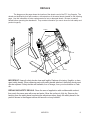
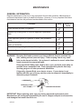
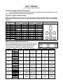
OPERATOR’S AND PARTS MANUAL LOG GRAPPLE SERIAL NUMBER: ___________________ MODEL NUMBER: ___________________ 800-456-7100 I www.paladinattachments.com Manual Number: MR15533 Part Number: LAF1142 Rev. 3 503 Gay Street, Delhi, IA 52223, United States of America Copyright © 11/5/13 4 MR15533 11/5/13 TABLE OF CONTENTS PREFACE .............................................................................................................................. 3 SAFETY PRECAUTIONS SAFETY STATEMENTS .............................................................................................. 4 GENERAL SAFETY PRECAUTIONS ..................................................................... 4-6 EQUIPMENT SAFETY PRECAUTIONS....................................................................7-8 DECALS DECAL PLACEMENT...................................................................................................9 DECALS......................................................................................................................10 INSTALLATION...................................................................................................................... 11 OPERATION..........................................................................................................................12 MAINTENANCE.....................................................................................................................13 SPECIFICATIONS ................................................................................................................14 BOLT TORQUE SPECIFICATIONS.......................................................................................15 WARRANTY...........................................................................................................................17 PARTS LOG GRAPPLE......................................................................................................18-19 11/5/13 MR15533 1 2 MR15533 11/5/13 PREFACE GENERAL COMMENTS Congratulations on the purchase of your new attachment! This product was carefully designed and manufactured to give you many years of dependable service. Only minor maintenance (such as cleaning and lubricating) is required to keep it in top working condition. Be sure to observe all maintenance procedures and safety precautions in this manual and on any safety decals located on the product and on any equipment on which the attachment is mounted. This manual has been designed to help you do a better, safer job. Read this manual carefully and become familiar with its contents. WARNING! Never let anyone operate this unit without reading the "Safety Precautions" and "Operating Instructions" sections of this manual. Always choose hard, level ground to park the vehicle on and set the brake so the unit cannot roll. Unless noted otherwise, right and left sides are determined from the operator’s control position when facing the attachment. NOTE: The illustrations and data used in this manual were current (according to the information available to us) at the time of printing, however, we reserve the right to redesign and change the attachment as may be necessary without notification. BEFORE OPERATION The primary responsibility for safety with this equipment falls to the operator. Make sure the equipment is operated only by trained individuals that have read and understand this manual. If there is any portion of this manual or function you do not understand, contact your local authorized dealer or the manufacturer to obtain further assistance. Keep this manual available for reference. Provide the manual to any new owners and/or operators. SAFETY ALERT SYMBOL This is the “Safety Alert Symbol” used by this industry. This symbol is used to warn of possible injury. Be sure to read all warnings carefully. They are included for your safety and for the safety of others working with you. SERVICE Use only manufacturer replacement parts. Substitute parts may not meet the required standards. Record the model and serial number of your unit on the cover of this manual. The parts department needs this information to insure that you receive the correct parts. SOUND AND VIBRATION Sound pressure levels and vibration data for this attachment are influenced by many different parameters: some items are listed below (not inclusive): • prime mover type, age, condition, with or without cab enclosure and configuration • operator training, behavior, stress level • job site organization, working material condition, environment Based on the uncertainty of the prime mover, operator, and job site, it is not possible to get precise machine and operator sound pressure levels or vibration levels for this attachment. NOTE: A list of all Paladin Patents can be found at http://www.paladinattachments.com/patents.asp. 11/5/13 MR15533 3 SAFETY STATEMENTS THIS SYMBOL BY ITSELF OR WITH A WARNING WORD THROUGHOUT THIS MANUAL IS USED TO CALL YOUR ATTENTION TO INSTRUCTIONS INVOLVING YOUR PERSONAL SAFETY OR THE SAFETY OF OTHERS. FAILURE TO FOLLOW THESE INSTRUCTIONS CAN RESULT IN INJURY OR DEATH. DANGER THIS SIGNAL WORD IS USED WHERE SERIOUS INJURY OR DEATH WILL RESULT IF THE INSTRUCTIONS ARE NOT FOLLOWED PROPERLY. WARNING THIS SIGNAL WORD IS USED WHERE SERIOUS INJURY OR DEATH COULD RESULT IF THE INSTRUCTIONS ARE NOT FOLLOWED PROPERLY. CAUTION NOTICE THIS SIGNAL WORD IS USED WHERE MINOR INJURY COULD RESULT IF THE INSTRUCTIONS ARE NOT FOLLOWED PROPERLY. NOTICE INDICATES A PROPERTY DAMAGE MESSAGE. GENERAL SAFETY PRECAUTIONS WARNING! READ MANUAL PRIOR TO INSTALLATION Improper installation, operation, or maintenance of this equipment could result in serious injury or death. Operators and maintenance personnel should read this manual, as well as all manuals related to this equipment and the prime mover thoroughly before beginning installation, operation, or maintenance. FOLLOW ALL SAFETY INSTRUCTIONS IN THIS MANUAL AND THE PRIME MOVER'S MANUAL(S). READ AND UNDERSTAND ALL SAFETY STATEMENTS Read all safety decals and safety statements in all manuals prior to operating or working on this equipment. Know and obey all OSHA regulations, local laws, and other professional guidelines for your operation. Know and follow good work practices when assembling, maintaining, repairing, mounting, removing, or operating this equipment. KNOW YOUR EQUIPMENT Know your equipment’s capabilities, dimensions and operations before operating. Visually inspect your equipment before you start, and never operate equipment that is not in proper working order with all safety devices intact. Check all hardware to ensure it is tight. Make certain that all locking pins, latches, and connection devices are properly installed and secured. Remove and replace any damaged, fatigued, or excessively worn parts. Make certain all safety decals are in place and are legible. Keep decals clean, and replace them if they become worn and hard to read. 4 MR15533 11/5/13 WARNING! GENERAL SAfETy PRECAUTIONS GENERAL SAFETY PRECAUTIONS PROTECT AGAINST fLyING DEbRIS always wear proper safety glasses, goggles, or a face shield when driving pins in or WARNING! PROTECT AGAINST FLYING DEBRIS out, or when any operation causes dust, flying debris, or any other hazardous mateAlways wear proper safety glasses, goggles or a face shield when driving pins in or rial. out, or when any operation causes dust, flying debris, or any other hazardous material. WARNING! OR SUPPORT RAISED EQUIPMENT WARNING! LOWERLOWER OR SUPPORT RAISED EQUIPMENT Do not work under raised booms without supporting Do support not use support mateDo not work under raised booms without supporting them. Dothem. not use rial made of concrete blocks, buckets, barrels, or other any other material material made of concrete blocks, logs,logs, buckets, barrels or any material that that could suddenly collapse or shift positions. Make sure support material is solid, could suddenly collapse or shift positions. Make sure support material is solid, notnot decayed, warped, twisted, or tapered. lower booms to ground level or on blocks. decayed, warped, twisted, or tapered. Lower booms to ground level or onto blocks. lower booms and attachments ground before leaving cab operator’s Lower booms and attachments to to thethe ground before leaving thethe cab or or operator’s station. station. WARNING! USE CARE WITH HyDRAULIC fLUID PRESSURE WARNING! USE CARE WITHfluid HYDRAULIC FLUID Hydraulic under pressure can PRESSURE penetrate the skin and cause serious injury or Hydraulicdeath. fluid under pressure can penetrate themay skinnot andbecause serious injury or hydraulic leaks under pressure visible. before connecting or dis- death. Hydraulic leaks under pressure mayyour not prime be visible. Before connecting or for detailed connecting hydraulic hoses, read mover’s operator’s manual disconnecting hydraulic readand yourdisconnecting prime movershydraulic operator’s manual for detailed instructions on hoses, connecting hoses or fittings. instructions on connecting and disconnecting hydraulic hoses or fittings. • Keep unprotected body parts, such as face, eyes, and arms as far away as • Keep unprotected bodyaparts, such as face, eyes, and arms far away asmay develop possible from suspected leak. Flesh injected with as hydraulic fluid possible from a suspected leak. Flesh injected with hydraulic fluid may develop gangrene or other permanent disabilities. gangrene or other permanent disabilities. • If injured by injected fluid, see a doctor at once. If your doctor is not familiar with • If injured by injected fluid, see a doctor at once. If your doctor is not familiar with this type of injury, ask him to research it immediately to determine proper treat this type of injury, ask him to research immediately to determine proper treatment. ment. • Wear safety glasses, protective clothing, and use a sound piece of cardboard or • Wear safety glasses, protective clothing, and use a piece of cardboard or wood wood when searching for hydraulic leaks. DO NOT USE YOUR HANDS! when searching for hydraulic leaks. DO NOT USE yOUR HANDS! SEE ILLUSTRATION. SEE ILLUSTRATION. CARDbOARD HyDRAULIC HOSE OR fITTING MAGNIfyING GLASS 4 11/5/13 76288 MR15533 5 GENERAL SAFETY PRECAUTIONS WARNING! DO NOT MODIFY MACHINE OR ATTACHMENTS Modifications may weaken the integrity of the attachment and may impair the function, safety, life, and performance of the attachment. When making repairs, use only the manufacturer’s genuine parts, following authorized instructions. Other parts may be substandard in fit and quality. Never modify any ROPS (Roll Over Protection Structure) or FOPS (Falling Object Protective Structure) equipment or device. Any modifications must be authorized in writing by the manufacturer. WARNING! SAFELY MAINTAIN AND REPAIR EQUIPMENT • Do not wear loose clothing, or any accessories that can catch in moving parts. • • • • If you have long hair, cover or secure it so that it does not become entangled in the equipment. Work on a level surface in a well-lit area. Use properly grounded electrical outlets and tools. Use the correct tool for the job at hand. Make sure they are in good condition for the task required. Wear the protective equipment specified by the tool manufacturer. WARNING! SAFELY OPERATE EQUIPMENT Do not operate equipment until you are completely trained by a qualified operator in how to use the controls, know its capabilities, dimensions, and all safety requirements. See your machine's manual for these instructions. • Keep all step plates, grab bars, pedals, and controls free of dirt, grease, debris, and oil. • Never allow anyone to be around the equipment when it is operating. • Do not allow riders on the attachment or the prime mover. • Do not operate the equipment from anywhere other than the correct operators position. • Never leave equipment unattended with the engine running or with this attachment in a raised position. • Do not alter or remove any safety feature from the prime mover or this attachment. • Know your work site safety rules as well as traffic rules and flow. When in doubt on any safety issue, contact your supervisor or safety coordinator for an explanation. WARNING! KNOW WHERE UTILITIES ARE Observe overhead electrical and other utility lines. Be sure equipment will clear them. 6 When digging, call your local utilities for location of buried utility lines, gas, water, and sewer, as well as any other hazard you may encounter. MR15533 11/5/13 EQUIPMENT SAFETY PRECAUTIONS WARNING! EXPOSURE TO RESPIRABLE CRYSTALLINE SILICA DUST ALONG WITH OTHER HAZARDOUS DUSTS MAY CAUSE SERIOUS OR FATAL RESPIRATORY DISEASE. It is recommended to use dust suppression, dust collection and if necessary personal protective equipment during the operation of any attachment that may cause high levels of dust. WARNING! REMOVE PAINT BEFORE WELDING OR HEATING Hazardous fumes/dust can be generated when paint is heated by welding, soldering or using a torch. Do all work outside or in a well ventilated area and dispose of paint and solvent properly. Remove paint before welding or heating. When sanding or grinding paint, avoid breathing the dust. Wear an approved respirator. If you use solvent or paint stripper, remove stripper with soap and water before welding. Remove solvent or paint stripper containers and other flammable material from area. Allow fumes to disperse at least 15 minutes before welding or heating. WARNING! END OF LIFE DISPOSAL At the completion of the useful life of the unit, drain all fluids and dismantle by separating the different materials (rubber, steel, plastic, etc.). Follow all federal, state and local regulations for recycling and disposal of the fluid and components. OPERATING THE ATTACHMENT • • • • • • • • • • • • 11/5/13 Do not exceed the lifting capacity of your prime mover. Operate only from the operator’s station. Do not use the log grapple to lift round bales. Grapples move quickly. Do not stand near or place extremities near or between grapple and implement. When operating on slopes, drive up and down, not across. Avoid steep hillside operation, which could cause the prime mover to overturn. Reduce speed when driving over rough terrain, on a slope, or turning, to avoid overturning the vehicle. An operator must not use drugs or alcohol, which can change his or her alertness or coordination. An operator taking prescription or over-the-counter drugs should seek medical advice on whether or not he or she can safely operate equipment. Never heap load heavy material where the combined weight of the attachment and material could exceed the rated lifting capacity of the prime mover. Be sure the load does not stick out too far in front of the attachment. A light load sticking out too far can have the same tipping effect as a heavy load carried in close. Never lift, move or swing loads over anyone. Lift the load slightly and make sure that the load is secure. If the load appears to be unstable, lower the load, open the grapple and reposition the load to attain full stability. Before exiting the prime mover, lower the attachment to the ground, turn off the prime mover’s engine, remove the key and apply the brakes. 7 MR15533 EQUIPMENT SAFETY PRECAUTIONS TRANSPORTING THE ATTACHMENT • • • • Travel only with the attachment in a safe transport position to prevent uncontrolled movement. Drive slowly over rough ground and on slopes. When driving on public roads use safety lights, reflectors, Slow Moving Vehicle signs etc., to prevent accidents. Check local government regulations that may affect you. Do not drive close to ditches, excavations, etc., cave in could result. Do not smoke when refueling the prime mover. Allow room in the fuel tank for expansion. Wipe up any spilled fuel. Secure cap tightly when done. MAINTAINING THE ATTACHMENT • • • • • 8 Before performing maintenance, lower the attachment to the ground, turn off the engine, remove the key and apply the brakes. Never perform any work on the attachment unless you are authorized and qualified to do so. Always read the operator service manual’s before any repair is made. After completing maintenance or repair, check for correct functioning of the attachment. If not functioning properly, always tag “DO NOT OPERATE” until all problems are corrected. Worn, damaged, or illegible safety decals must be replaced. New safety decals can be ordered from FFC free of charge. Never make hydraulic repairs while the system is under pressure. Serious personal injury or death could result. Never work under a raised attachment. MR15533 11/5/13 DECALS The diagram on this page shows the location of the decals used of the FFC Log Grapple. The decals are identified by their part numbers, with reductions of the actual decals located on the following page. Use this information to order replacements for lost or damaged decals. Be sure to read all decals before operating the attachment. They contain information you nee to know for both safety and product longevity. 50-0737 RDL3139 RDL3103 40150 50-0724 Serial # Tag RDL3139 IMPORTANT: Keep all safety decals clean and legible. Replace all missing, illegible, or damaged safety decals. When replacing parts with safety decals attached, the safety decals must also be replaced. Safety decals are available, free of charge, from your local dealer or Paladin. REPLACING SAFETY DECALS: Clean the area of application with nonflammable solvent, then wash the same area with soap and water. Allow the surface to fully dry. Remove the backing from the safety decal, exposing the adhesive surface. Apply the safety decal to the position shown in the diagram above and smooth out any bubbles. 11/5/13 MR15533 9 DECALS PART # 40150 WARNING! READ MANUAL PART # 50-0724 WARNING! HIGH PRESSURE FLUID PART # 50-0737 WARNING! PINCH POINT PART # RDL3103 WARNING! FALLING LOAD PART # RDL3125 WARNING! CRUSH HAZARD 10 PART # RDL3139 SAFETY INSTRUCTIONS MR15533 11/5/13 INSTALLATION INSTALLATION Your Log Grapple was shipped complete with the appropriate mounting for your specific unit. The hydraulic hoses and couplers are included for skid steer loader applications only. HYDRAULIC CONNECTIONS On all applications other than skid steer loaders, two hydraulic hoses are required to go from the auxiliary hydraulics on your prime mover to the "T" fitting on the Log Grapple. These hoses require a #6 Female JIC fitting on one end while the other end will need to fit up to the auxiliary hydraulics on your prime mover. (Make certain these hoses are long enough to extend, without stretching, from the auxiliary hydraulics to the cylinder, while loader arms are at maximum height and at full dump position.) Install the attachment by following your prime mover operator's manual for installing an attachment. WARNING! To Avoid Serious Personal Injury, make sure the attachment is securely latched to the attachment mechanism of your unit. Failure to do so could result in separation of the attachment from the unit. Connect the hydraulic quick couplers to the auxiliary hydraulics, and route the hoses in such a fashion as to prevent chafing and pinching. Start engine and slowly cycle the cylinders several times to purge system of air and check for proper hydraulic connection, hose routing, and hose length. Check the attachment for proper assembly, installation and hydraulic leaks. DETACHING On firm level ground, close the grapple and lower the attachment until it is level and approximately 2" off the ground. Turn off the engine. Move the control levers back and forth to relieve pressure in line. Disconnect couplers. NOTE: Connect couplers together or install caps to prevent contaminants from entering the hydraulic system. Follow your power unit operator's manual for detaching (removing) an attachment. NOTE: Frequent lubrication of grease fittings at the pivot pins locations with a multipurpose grease will greatly increase life of the product. 11/5/13 MR15533 11 OPERATION POSITIONING Be aware of how the load’s weight is distributed. For well balanced loads: Position forks so that the load is centered on the forks. Close grapple. For unbalanced loads: Position forks so that the heavy side of the load is toward the Log Grapple’s main frame, (closest to the machine). Close grapple. For wide loads: Position forks under area which will balance the load. Close grapple. LIFTING WARNING! Falling debris may result in death or serious injury. Do not lift any load that cannot be safely secured by the grapple. WARNING! Do not lift any load while bystanders are near, keep other people away while operating equipment. • • Be sure you are on solid ground. Always lift load slightly to be sure load is secure. If the load appears to be unstable, lower forks, open grapple and reposition forks to achieve best stability. TRANSPORTING • • • • • • • 12 Always make sure that the load is well balanced and secure before transporting. Be aware of, and avoid, any obstacles, bumps or holes in your intended path. Keep load close to the ground. Do not make sharp turns. Slow down before making any turn. Accelerate and brake gradually. Check the load frequently to be sure it remains stable and balanced. MR15533 11/5/13 MAINTENANCE GENERAL INFORMATION Regular maintenance is the key to long equipment life and safe operation. Maintenance requirements have been kept to an absolute minimum. However, it is very important that these maintenance functions be performed as described in this section. Procedure Daily Check all bolts and nuts for tightness. Replace any missing bolts or nuts with approved replacement parts. Check hydraulic system for hydraulic oil leaks. See procedure below. Visually inspect the machine for worn parts or cracked welds, and repair as necessary. Check for missing or illegible Safety / Warning Decals. Lubricate all grease fittings. Every 10 Hours WARNING! Escaping fluid under pressure can have sufficient force to penetrate the skin, causing serious personal injury. Fluid escaping from a very small hole can be almost invisible. Use a piece of cardboard or wood, rather than hands to search for suspected leaks. Keep unprotected body parts, such as face, eyes, and arms as far away as possible from a suspected leak. Flesh injected with hydraulic fluid may develop gangrene or other permanent disabilities. If injured by injected fluid, see a doctor at once. If your doctor is not familiar with this type of injury, ask him or her to research it immediately to determine proper treatment. CARDBOARD HYDRAULIC HOSE OR FITTING MAGNIFYING GLASS IMPORTANT: When replacing parts, use only factory-approved replacement parts. Manufacturer will not accept responsibility for use of unapproved parts or accessories, and damages that result from their use. 11/5/13 MR15533 13 PRIME MOVER/LOADER SPECIFICATIONS IMPORTANT Exceeding any of the maximum recommended prime mover/loader specifications CAN result in damage to this product and WILL void all FFC warranties. DESCRIPTION SPECIFICATIONS Lift Capacity of Prime Mover's Loader Hydraulic Pressure Output Rear Ballast Model Number Overall Height LAF1142 48.6" 6,400 lbs. maximum 4,000 psi. maximum As required to maintain full prime mover stability. (Note the shipping weight of your model, then see the operator’s manual(s) for your prime mover and loader, and quick attach for ballasting needs.) ATTACHMENT SPECIFICATIONS Grapple Open Overall Depth Tine Length Usable Tooth Shipping Weight 49.3" 37.85" 29" 28.4" 790 lbs. All replacement hydraulic hoses and fittings must have a minimum rated working pressure of 4,000 psi. 14 MR15533 11/5/13 BOLT TORQUE BOLT TORQUE SPECIFICATIONS GENERAL TORQUE SPECIFICATION TABLES 8VHWKHIROORZLQJFKDUWVZKHQGHWHUPLQLQJEROWWRUTXHVSHFL¿FDWLRQVZKHQVSHFLDOWRUTXHVDUHQRW given. Always use grade 5 or better when replacing bolts. SAE BOLT TORQUE SPECIFICATIONS NOTE: The following torque values are for use with extreme pressure lubricants, plating or hard washer applications Increase torque 15% when using hardware that is unplated and either dry or lubricated with engine oil. SAE GRADE 5 TORQUE Bolt Size Inches Millimeters 1/4 6.35 5/16 7.94 3/8 9.53 7/16 11.11 1/2 12.70 9/16 14.29 5/8 15.88 3/4 19.05 7/8 22.23 1 25.40 1-1/8 25.58 1-1/4 31.75 1-3/8 34.93 1-1/2 38.10 Pounds Feet UNC UNF 8 9 14 19 30 36 46 54 68 82 94 112 128 153 230 275 340 408 493 592 680 748 952 1054 1241 1428 1649 1870 Newton-Meters UNC UNF 11 12 19 23 41 49 62 73 92 111 127 152 174 207 312 373 461 553 668 803 922 1014 1291 1429 1683 1936 2236 2535 SAE GRADE 8 TORQUE Pounds Feet UNC UNF 10 13 20 25 38 46 60 71 94 112 136 163 187 224 323 395 510 612 765 918 1088 1224 1547 1700 2023 2312 2686 3026 Newton-Meters UNC UNF 14 18 27 34 52 62 81 96 127 152 184 221 254 304 438 536 691 830 1037 1245 1475 1660 2097 2305 2743 3135 3642 4103 METRIC BOLT TORQUE SPECIFICATIONS %ROWKHDGLGHQWL¿FDWLRQPDUNVDVSHUJUDGH NOTE: Manufacturing Marks Will Vary %ROWKHDGLGHQWL¿FDWLRQPDUNVDVSHUJUDGH NOTE: The following torque values are for use with metric hardware that is unplated and either dry or lubricated with engine oil. Reduce torque 15% when using hardware that has extreme pressure lubricants, plating or hard washer applications. Size of Bolt Grade No. 5.6 Pitch (mm) Pounds Feet 3.6-5.8 Newton-Meters 4.9-7.9 Pitch (mm) Pounds Feet - Newton-Meters - M6 8.8 10.9 1.0 5.8-.4 7.2-10 7.9-12.7 9.8-13.6 - - - M8 8.8 10.9 M10 8.8 10.9 M12 8.8 10.9 M14 8.8 10.9 M16 8.8 10.9 M18 8.8 10.9 7.2-14 9.8-19 1.25 17-22 20-26 23-29.8 27.1-35.2 20-25 27.1-33.9 1.5 34-40 38-46 46.1-54.2 51.5-62.3 28-34 37.9-46.1 1.75 51-59 57-66 69.1-79.9 77.2-89.4 49-56 66.4-75.9 2.0 81-93 96-109 109.8-126 130.1-147.7 67-77 90.8-104.3 2.0 116-130 129-145 157.2-176.2 174.8-196.5 88-100 119.2-136 2.0 150-168 175-194 203.3-227.6 237.1-262.9 108-130 146.3-176.2 2.5 186-205 213-249 252-277.8 288.6-337.4 5.6 5.6 5.6 5.6 5.6 5.6 5.6 M20 11/5/13 76312 8.8 10.9 MR15533 12-17 16.3-23 1.0 19-27 22-31 25.7-36.6 29.8-42 20-29 27.1-39.3 1.25 35-47 40-52 47.4-63.7 54.2-70.5 31-41 42-55.6 1.25 56-68 62-75 75.9-92.1 84-101.6 52-64 70.5-86.7 1.5 90-106 107-124 122-143.6 145-168 69-83 93.5-112.5 1.5 120-138 140-158 162.6-187 189.7-214.1 100-117 136-158.5 1.5 177-199 202-231 239.8-269.6 273.7-313 132-150 178.9-203.3 1.5 206-242 246-289 279.1-327.9 333.3-391.6 15 29 THIS PAGE IS INTENTIONALLY BLANK 16 MR15533 11/5/13 Limited Warranty Except for the Excluded Products as described below, all new products are warranted to be free from defects in material and/or workmanship during the Warranty Period, in accordance with and subject to the terms and conditions of this Limited Warranty. 1. Excluded Products. The following products are excluded from this Limited Warranty: (a) Any cable, part that engages with the ground (i.e. sprockets), digging chain, bearing, teeth, tamping and/or demolition head, blade cutting edge, pilot bit, auger teeth and broom brush that either constitutes or is part of a product. (b) Any product, merchandise or component that, in the opinion of Paladin Light Construction1, has been (i) misused; (ii) modified in any unauthorized manner; (iii) altered; (iv) damaged; (v) involved in an accident; or (vi) repaired using parts not obtained through Paladin Light Construction. 2. Warranty Period. The Limited Warranty is provided only to those defects that occur during the Warranty Period, which is the period that begins on the first to occur of: (i) the date of initial purchase by an end-user, (ii) the date the product is first leased or rented, or (iii) the date that is six (6) months after the date of shipment by Paladin Light Construction as evidenced by the invoiced shipment date (the “Commencement Date”) and ends on the date that is twelve (12) months after the Commencement Date. 3. Terms and Conditions of Limited Warranty. The following terms and conditions apply to the Limited Warranty hereby provided: (a) the product. Option to Repair or Replace. Paladin Light Construction shall have the option to repair or replace (b) Timely Repair and Notice. In order to obtain the Limited Warranty, (i) the product must be repaired within thirty (30) days from the date of failure, and (ii) a claim under the warranty must be submitted to Paladin Light Construction in writing within thirty (30) days from the date of repair. (c) Return of Defective Part or Product. If requested by Paladin Light Construction, the alleged defective part or product shall be shipped to Paladin Light Construction at its manufacturing facility or other location specified by Paladin Light Construction, with freight PRE-PAID by the claimant, to allow Paladin Light Construction to inspect the part or product. Claims that fail to comply with any of the above terms and conditions shall be denied. LIMITATIONS AND EXCLUSIONS. THIS LIMITED WARRANTY IS IN LIEU OF ALL OTHER WARRANTIES, EXPRESS OR IMPLIED, INCLUDING WITHOUT LIMITATION THE WARRANTIES OF MERCHANTABILITY, FITNESS FOR A PARTICULAR PURPOSE AND ANY WARRANTY BASED ON A COURSE OF DEALING OR USAGE OF TRADE. IN NO EVENT SHALL PALADIN LIGHT CONSTRUCTION BE LIABLE FOR CONSEQUENTIAL OR SPECIAL DAMAGES. IN NO EVENT SHALL PALADIN LIGHT CONSTRUCTION BE LIABLE FOR ANY LOSS OR CLAIM IN AN AMOUNT IN EXCESS OF THE PURCHASE PRICE, OR, AT THE OPTION OF PALADIN LIGHT CONSTRUCTION, THE REPAIR OR REPLACEMENT, OF THE PARTICULAR PRODUCT ON WHICH ANY CLAIM OF LOSS OR DAMAGE IS BASED. THIS LIMITATION OF LIABILITY APPLIES IRRESPECTIVE OF WHETHER THE CLAIM IS BASED ON BREACH OF CONTRACT, BREACH OF WARRANTY, NEGLIGENCE OR OTHER CAUSE AND WHETHER THE ALLEGED DEFECT IS DISCOVERABLE OR LATENT. Attachment Technologies Inc., a subsidiary of Paladin Brands Holding, Inc. (PBHI) is referred to herein as Paladin Light Construction. February 10, 2010 1 LOG GRAPPLE PARTS ILLUSTRATION 9 11 10 3 17 10 10 12 2 15 6 16 4 8 7 14 13 5 8 1 18 MR15533 11/5/13 LOG GRAPPLE PARTS LIST ITEM QTY. LAF1142 1 2 3 4 5 6 7 8 9 10 11 12 13 14 15 16 17 DESCRIPTION 1 LAF1160 Main Frame Weldment 1 LAF1161 Grapple Weldment 2 LAF3100 Upper Cylinder Pin 2 LAF3098 Grapple Pivot Pin 2 LAF3099 Lower Cylinder Pin 2 1049 Grade 5 Hex Head Cap Screw .38" x 2.5" 2 1048 Grade 5 Hex Head Cap Screw .38" x 2.25" 4 1837 Grade 5 Lock Torque Nut .38" 2 RHW1041 Grade 8 Hex Head Cap Screw .25" x 2" 8 6616 Grease Zerk .25"-28 tpi Self-tap 2 1629 Grade 5 Lock Nylon Nut .25" 4 3434 Elbow 90° 6MBO-6MJ 2 3217 #6 Bulkhead Jam Nut .56"-18 2 3498 Tee Bulkhead Branch 6MJ-6MJ-6MJ 2 37973 Hose .38" x 32" 6FJX-6FJX 2 38264 Hose .38" x 22" 6FJX-6FJX 2 LAF4606 Hydraulic Cylinder 2" x 1.25" x 8" 4000-psi (Cylinder Seal Kit = LAF4617) 11/5/13 MR15533 19 MR15533