1
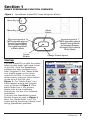
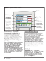
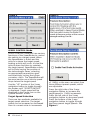
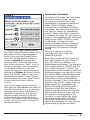
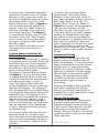
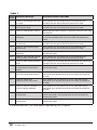
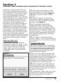
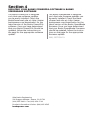
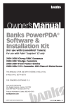
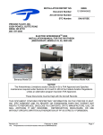
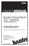
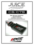
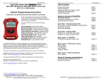
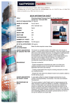
Advanced User Manual
Banks SpeedBrake
For use with Palm® Tungsten™ E2
2006-2008 Chevy/GMC 6.6L (LBZ/LMM)
Turbo-Diesel Pickup
THIS MANUAL IS FOR USE WITH KITS 55423, 55424, 55429 & 55430
Gale Banks Engineering
546 Duggan Avenue • Azusa, ca 91702
(626) 969-9600 • Fax (626) 334-1743
Product Information & Sales: (888) 635-4565
bankspower.com
©2009 Gale Banks Engineering
09/04/09 PN 97233 v.3.0
Table of Contents
Section 1 . . . . . . . . . . . . . . . . . . . . . . 3
Banks SpeedBrake Function Overview
Section 2 . . . . . . . . . . . . . . . . . . . . . . 9
Self Diagnostics
Section 3 . . . . . . . . . . . . . . . . . . . . . 11
Checking and Clearing OBD II Diagnostic
Codes
Section 4 . . . . . . . . . . . . . . . . . . . . . 12
Updating Your Banks PowerPDA
Software & Banks SpeedBrake Firmware
2
97233 v.3.0
Section 1
Banks Speedbrake Function overview
Figure 1 SpeedBrake PowerPDA 5-way Navigation Button
Home Key
Menu Key
Mode
Select
Decrease speed in 1
MPH intervals when in
Speed Control Mode
or decrease Braking
Strength level when
in Brake Mode
Center
Button
Startup
Turn the PowerPDA on with the power
button on the upper right hand corner
of the PDA. Once the SpeedBrake
software has been installed on the
Palm Tungsten E2, the “Banks Brake”
icon should appear on the Home
screen of the PDA. To access the
Home screen, press the Home button
on the face of the PDA (see
Figure 1). The “Banks Brake” icon
should appear among the program
icons as shown in Figure 2. If the
Banks Brake icon is not present,
please refer to the installation
instructions, Section 4 for Software
Installation.
Increase speed in 1
MPH intervals when in
Speed Control Mode
or Increase Braking
Strength level when in
Brake Mode
Change Preset Speed
Figure 2 BanksBrake icon Shown
with Tuner program installed.
To access the SpeedBrake System
Monitor Screen as seen in Figure 3,
press the “Banks Brake” icon. This
screen will be the primary display used
during SpeedBrake operation.
97233 v.3.0
3
Figure 3 System Monitor Screen
Power
Vehicle Speed
Operating
Gear
SpeedBrake
braking effort
Engine
Temperature
Transmission
Temperature
Speed Brake
System Status
SpeedBrake
Mode
On Screen
Alert Display
Brake Level/
Braking Speed
PowerPDA LCD Properties
SpeedBrake Modes
The screen of the PowerPDA can
be adjusted for brightness to
accommodate the ambient light
conditions as well as individual
preference. From the System Menu,
press the LCD Properties button (see
Figure 4). Read the instructions
provided and adjust the settings to
your liking.
The SpeedBrake has three operating
modes; ON, SPEED CONTROL and
OFF. In the ON mode, the SpeedBrake
will activate and will downshift
the transmission and close the
turbocharger vanes to achieve braking
and decelerate your vehicle down to
15 MPH. In SPEED CONTROL mode,
the SpeedBrake varies the position of
the turbocharger vanes and selects an
appropriate gear in order to maintain a
pre-selected target speed. In the OFF
mode, the vehicle will behave as if the
SpeedBrake is not present.
Note: The PowerPDA has an automatic
shut down feature. Once the key is
turned off, the PowerPDA will detect
that a signal is no longer present
from the SpeedBrake and it will
automatically power down after a few
seconds. This is to prevent excessive
usage of the PDA battery. With the Key
in the “Run” position, the SpeedBrake
will be activated and all features will
be accessible.
4
97233 v.3.0
ON Mode
Mode selection is achieved by
pressing the “UP” portion of the 5-way
navigation button (see Figure 1).
Toggle through the modes until the
SpeedBrake Mode display indicates
“ON” (see Figure 3).
Strength Settings
Foot Brake Activation
While in the ON mode, there are three
strength selections available; HIGH,
medium (MED) and LOW. The purpose
of these settings is to allow for
variations in vehicle weight as well as
user preference. The strength setting
is displayed in the center box on the
System Monitor Screen.
Since the SpeedBrake is an auxiliary
braking device, the user may select
options that provide the best interface
method for individual driving style or
vehicle load conditions. The use of the
foot brake will have varied influence
on overall braking depending on the
SpeedBrake mode that is selected. A
selection checkbox allows the user
to either ENABLE or DISABLE the Foot
Brake Activation feature.
The HIGH strength setting achieves
the highest level of braking activity
by aggressively downshifting
the transmission and closing the
turbocharger vanes. This setting is
recommended for heavily loaded
vehicles or whenever aggressive
braking is desired. The medium (MED)
strength setting achieves a moderate
level of braking activity by slightly
delaying transmission downshifts.
This setting is recommended for
moderately loaded vehicles. The
LOW strength setting achieves a
lower level of braking activity and is
recommended for lightly loaded or
unloaded vehicles. The LOW setting
may also be appropriate for daily
driving.
Caution: Using the HIGH setting
with a lightly loaded vehicle will
result in VERY aggressive braking
activity. Become familiar with the
characteristics of the Strength
settings before encountering
slippery road conditions (i.e.
snow or rain).
To change the Strength setting while in
the ON mode, press the left side of the
5-way navigation button to decrease
the strength and the right side of the
5-way navigation button to increase
strength (see Figure 1).
When ON mode is selected and Foot
Brake Activation is disabled, braking
will occur any time that the driver
releases the accelerator pedal and
vehicle speed is greater 15 MPH,
regardless of whether or not the
foot brakes are used. When Foot
Brake Activation is enabled, the
SpeedBrake will only become active
if the foot brake is applied. Once
the driver releases the foot brake,
the SpeedBrake will deactivate. In
this condition, the foot brake pedal
effectively becomes an “On” switch
for the SpeedBrake. Only slight pedal
pressure is required to activate the
SpeedBrake. Some drivers will find
that this method of brake activation is
preferable to constant brake activity.
To access the Foot Brake Activation
selection checkbox, from the System
Monitor Screen, press the center of
the 5-way navigation button to access
the System Menu. Press the “Foot
Brake” button as shown in Figure 4.
The on screen text will explain the
feature. Press the “Next” button to
read the remainder of the text and
access the checkbox. See Figure 5.
To activate the feature, press on the
checkbox. Press the “Back” button
once to return to the System Menu
and again to return to the System
Monitor screen.
Note: the default condition for the Foot
Brake Activation feature is disabled.
97233 v.3.0
5
Figure 4
Figure 5
SPEED CONTROL Mode
SPEED CONTROL mode will use various
functions of the SpeedBrake to control
the vehicle to a target speed. When
the SpeedBrake is active and the
vehicle is above the target speed,
braking activity will occur to slow the
vehicle down and then to maintain
the target speed. SpeedBrake activity
will include varying the position of
the turbocharger vanes, selecting
an appropriate transmission gear
and selectively locking the torque
converter clutch. The SpeedBrake will
become inactive once vehicle speed
drops below the target speed.
Use the “UP” portion of the 5-way
navigation button to toggle through
the modes until “SPEED CONTROL”
is displayed. Target speed will be
displayed in the center box on the
System Monitor screen.
Target Speed Selection
There are two methods available for
target speed selection. The target
speed can be increased or decreased
from its current value in increments
6
97233 v.3.0
of 1 MPH, or the user can select from
three different preset speeds, which
are adjustable.
Press the right side of the 5-way
navigation button to increase the
target speed in 1 MPH increments.
Press the left side of the 5-way
navigation button to decrease speed.
Press the bottom of the 5-way
navigation button to toggle through
the three preset target speeds. See
Figure 1.
Figure 6
To change the target speed presets,
from the System Monitor screen, press
the center of the 5-way navigation
button to access the System Menu.
Press the “Speed Select” button as
shown in Figure 4 to access the
dialog screens. Read the text in the
first screen and press “Next” to go to
the second screen. Use the increase
or decrease buttons to alter the
values for the three speed presets as
desired (See Figure 6). When finished,
press the “Done” button to save the
selections and return to the System
Menu screen. Press the “Back” button
to return to the System Monitor
screen.
Note: If the target speed cannot be
met after the SpeedBrake has taken all
possible actions to do so, an advisory
message to the driver will display in
the Status Indicator on the System
Monitor screen instructing the use
of the foot brake to help slow the
vehicle. This feature may be disabled
in the “On Screen Alerts” section of
the System Menu.
Foot Brake Activation
As with the ON mode, the Foot Brake
Activation feature allows the user
to customize the function of the
SpeedBrake to individual preference.
When SPEED CONTROL mode is
selected and Foot Brake Activation
is disabled, any use of the foot brake
will have no impact on SpeedBrake
activity. When Foot Brake Activation
is enabled, whenever the foot brake is
applied, the SpeedBrake will effectively
switch from SPEED CONTROL mode
to ON mode, closing the turbo
vanes to provide maximum braking
and downshifting the transmission
according to the selected Strength
setting.
Note: This change in braking
conditions will not change the
PowerPDA display.
Depending on the vehicle speed and
the target speed, the driver may or
may not notice any difference in
SpeedBrake functionality. For example,
if the target speed is 50 MPH and the
actual vehicle speed is 60 MPH, the
SpeedBrake will be selecting maximum
braking strategy in an attempt to slow
the vehicle down, therefore when the
foot brake is applied, there will be no
noticeable increase in SpeedBrake
activity. However, if the actual vehicle
speed is only 45 MPH, lower than the
target speed, the SpeedBrake will
not be providing any braking effect.
Therefore, when the foot brake is
applied, braking activity will become
much greater and the driver will feel
an increase in braking effect. This
condition is useful when the driver
has selected the SPEED CONTROL
mode and conditions require the
vehicle to slow down or stop, such as
approaching a highway off-ramp.
97233 v.3.0
7
To access the Foot Brake Activation
selection checkbox, from the System
Monitor Screen, press the center of
the 5-way navigation button to access
the System Menu. Press the “Foot
Brake” button as shown in Figure 4.
The on screen text will explain the
feature. Press the “Next” button to
read the remainder of the text and
access the checkbox. See Figure 5.
To activate the feature, press on the
checkbox. Press the “Back” button
once to return to the System Menu
and again to return to the System
Monitor screen.
Note: The default condition for the
Foot Brake Activation feature is
disabled.
System Status Indicator/On
Screen Alerts
The System Status Indicator is used in
conjunction with On Screen Alerts and
will inform the user of any important
messages. Under normal conditions,
the indicator status will be highlighted
green and will have a green
checkmark in the window as shown
in Figure 3. The user has the option
of setting warning alerts if either the
coolant or transmission temperatures
exceed preset values. In such a
case, the System Status Indicator
will be highlighted red and a warning
message will appear. This warning is
also accompanied by an audible alarm.
The threshold temperature values are
adjustable from 180 degrees to 250
degrees and the audible alert volume
may be set to low, medium, high or
silent. The System Status Indicator
will also communicate any faults that
may be detected in the SpeedBrake
circuitry, allowing for quick and easy
troubleshooting.
The System Status Indicator will also
alert the driver to a condition that
even with maximum braking effort the
vehicle is still accelerating. Using the
manual Foot Brake is required in this
situation.
8
97233 v.3.0
To access the On Screen Alerts
feature setup, from the System
Monitor screen, press the center of
the 5-way navigation button to access
the System Menu. Press the “On
Screen Alerts” button as shown in
Figure 4 to access the temperature
selection and the alert volume
selection. Use the “Decrease” and
“Increase” buttons to select suitable
settings for temperature and select
the desired volume by pressing the
volume buttons. A sample of the alert
will sound for reference. When you
have completed your selections, press
the “Back” button to return to the
System Menu. Press the “Back” button
again to return to the System Monitor
screen.
Operation/Driving
Now that you are familiar with the
features that are available with the
Banks SpeedBrake, it is recommended
that you experiment with the various
settings prior to using the braking
features in a towing situation. Under
light load conditions on local streets,
the ON mode in the medium (MED)
setting is an appropriate starting
condition to provide a reasonable
demonstration that the brake is
functioning.
Anytime the brake is active and the
foot brake is applied, the vehicle
will not up shift until the throttle is
pressed. This is also true even if cruise
control is resumed.
Wheel Slip Detection
The Banks SpeedBrake continuously
monitors wheel speeds to detect
possible slippage caused by braking.
If this occurs, the brake will shut off
until traction is regained and then
remain off for 30 seconds. This will be
communicated as fault via the System
Status Indicator.
-END, SECTION 1-
Section 2
SELF DIAGNOSTICS
The SpeedBrake stores a running log of
all events that affect its performance.
This log may be used to identify
any diagnostic concerns with the
SpeedBrake.
1. Press the center button on the
5-way navigator to take you to the
System Menu screen.
Figure 7
2. Touch the button labeled ‘Next>’
to move to the second screen of the
System Menu.
3. Next, touch the ‘Self Diagnostics’
button. See Figure 7.
4. The ‘Self Diagnostics’ screen
displays a log of diagnostic events
related to the Banks SpeedBrake. See
Figure 8. The ‘Logged Events’ list
takes a moment to update each time
this screen is opened (as indicated
by a slight flickering of the list). Once
the list is updated, the most current
event will appear at the top of the
list. Each event has an associated
timestamp and description, which will
be displayed below the list when that
event is highlighted. Each key cycle
of the vehicle produces a minimum
of two logged events. Table 1 lists
the possible diagnostic codes and
corrective action.
5. Touch the button labeled ‘Down’
to scroll down through the recorded
events.
Figure 8
6. Touch the button labeled ‘Up’ to
scroll up through the recorded events.
To view a recorded event touch the
event item and it will display right
below the log window. See Figure 8.
7. Touch the ‘<Back’ button to return
to the System Monitor screen.
8. A pop-up “Log-file” screen, will
appear asking you if you want to erase
the contents of the log. Press ‘No’ to
keep contents on Log-file or ‘Yes’, to
erase Log-file.
-END, SECTION 2-
97233 v.3.0
9
Table 1
Flash
Code
PDA Error Message
Corrective Action- LBZ/ LMM
1.1
Code 11: VGT control input out
of range
Turn ignition OFF and check the 24-Pin connector. Turn
ignition back ON and re-check for presence of code.
1.2
Code 12: Vane Position Sensor
input out of range.
Turn ignition OFF and check the 24-Pin connector. Turn
ignition back ON and re-check for presence of code.
1.3
Code 13: Rear wheels slipping
None required. When traction is regained, error will clear after
30 seconds.
1.4
Code 14: Low power voltage
detected.
Turn ignition OFF and check the Fuse Tap and the Ground
O-ring. Turn ignition back ON and re-check for presence of
code.
2.1
Code 21: VGT control output
malfunction.
Turn ignition OFF and check the 24-Pin connector. Turn
ignition back ON and re-check for presence of code.
2.2
Code 22: VGT control output
overcurrent.
Turn ignition OFF and check the 24-Pin connector. Turn
ignition back ON and re-check for presence of code.
2.3
Code 23: Low relay voltage
detected.
Turn ignition OFF. Turn ignition back ON and re-check for
presence of code.
2.4
Code 24: Vane Position Sensor
voltage output malfunction.
Turn ignition OFF and check the 24-Pin connector. Turn
ignition back ON and re-check for presence of code.
3.1
Code 31: OBD communication
error.
Turn ignition off and check the OBD connector and cable. Turn
ignition back ON and re-check for presence of code.
3.2
Code 32: Internal module
malfunction or intermittent
power.
Turn ignition OFF. Turn ignition back ON and re-check for
presence of code.
3.3
Code 33: OBDII CAN
communication output error.
Turn ignition OFF and check the 16-Pin C100 Intercepting
connector. Turn ignition back ON and re-check for presence
of code.
3.4
Code 34: OBDII CAN
communication input error.
Turn ignition OFF and check the 16-Pin C100 Intercepting
connector. Turn ignition back ON and re-check for presence
of code.
4.2
Code 42: Torque Converter
Clutch slippage detected.
Turn ignition OFF and check the 16-Pin C100 Intercepting
connector. Turn ignition back ON and re-check for presence
of code.
4.3
Code 43: Shift control
malfunction.
Turn ignition OFF and check the 16-Pin C100 Intercepting and
20-Pin connectors. Turn ignition back ON and re-check for
presence of code.
4.4
Code 44: Internal memory
malfunction.
Turn ignition OFF. Turn ignition back ON and re-check for
presence of code.
If problem persists, call Gale Banks Engineering Tech Support.
10
97233 v.3.0
Section 3
CHECKING AND CLEARING OBD II DIAGNOSTIC Trouble CODES
Diagnostic Trouble Codes (DTC) are
error codes that appear when there
is a problem with your vehicle. If your
vehicle displays a check engine light,
DTC’s will be available to assist in
diagnosing the problem. You can use
the PowerPDA to run a vehicle system
check and display these DTC(s). A
code will be given along with a brief
description of the problem, a full
description of the code will display in
a pop up window when the code is
highlighted. You may reference your
vehicle service manual for description
and possible corrective action to fix
the problem. Once the problem has
been repaired you can clear the code
to turn the check engine light off.
Note: Keep a written record of the DTC
code(s) that display on your PowerPDA
for future reference before clearing
them.
Check for OBD II DTC
If any vehicle DTC(s) are present,
troubleshoot/repair the cause. Once
the cause is properly remedied, touch
‘Clear Codes’ and then ‘Check for
Codes’ again to verify the problem
is fixed (the ODB ll code should not
re-appear).
Figure 9
1. Press the center button on the
5-way navigator to take you to the
System Menu screen. See Figure 4.
2. Next, touch the ‘OBD II Codes’
button.
3. With the ignition in the on/run
position or with the engine running,
touch the button labeled ‘Check For
Codes’. See Figure 9.
Note: The Banks SpeedBrake
PowerPDA will check for vehicle
diagnostic codes and display either
the p-code with a brief description of
the code or the message “Done! – No
Codes Present”. For a full description
of the code, highlight the code and a
window will pop up with a detailed
explanation.
4. To return to the System Menu
touch ‘<Back’. If DTC were found and
you would like to clear them, proceed
to step 5.
Clearing OBD II DTC
5. After checking for and reviewing
any DTC problem, touch ‘Clear Codes’
to erase them from the vehicle ECU.
If multiple codes are present and the
underlying problem has been fixed,
they will all be cleared.
Note: To clear codes the ignition key
must be in the On/Run position, but
the engine must NOT be running. If the
engine is running, Banks SpeedBrake
PowerPDA will display a pop-up
message instructing you to check the
ignition key is in the ON position.
6. Press ’Check For Codes’ again to
verify the OBD II codes were erased.
Some status monitor codes require a
certain amount of engine “run time” in
order to be cleared.
7. If diagnostic codes reoccur on your
vehicle, you should investigate the
underlying problem to correct it.
-END, SECTION 397233 v.3.0
11
Section 4
Updating Your Banks PowerPDA Software & Banks
SpeedBrake Software
The Banks PowerPDA is designed
such that new software updates
can be easily installed. Check the
BanksPower web site at <http://www.
bankspower.com/downloads> for the
latest version of the Banks PowerPDA
software. Once you have determined
that your Banks PowerPDA Should be
updated, follow the instructions on
the page for the appropriate software
update.
The Banks SpeedBrake is designed
such that new firmware updates can
be easily installed. Check the BanksPower web site at <http://www.
bankspower.com/downloads> for the
latest version of the Banks SpeedBrake
firmware. Once you have determined
that your Banks SpeedBrake Firmware
should be updated, follow the instructions on the page for the appropriate
firmware update.
END, SECTION 10-
Gale Banks Engineering
546 Duggan Avenue • Azusa, ca 91702
(626) 969-9600 • Fax (626) 334-1743
Product Information & Sales: (888) 635-4565
bankspower.com