1
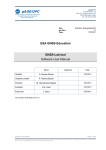
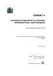
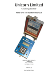
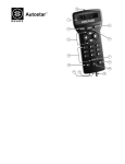
Banks PowerPDA®
Software &
Installation Kit
(For use with EconoMind® Tuners)
For use with Palm® Tungsten™ E2 only
2001-2008
2003-2007
2003-2009
2003-2006
Chevy/GMC Duramax
Dodge Cummins
Ford Power Stroke
5.9L Cummins ISB Class-A Motorhome
THIS MANUAL IS FOR USE WITH Systems 61100, 61104,
61108, 61112, 63771-63776
FOR POWERPDA SOFTWARE V1.8
Gale Banks Engineering
546 Duggan Avenue • Azusa, ca 91702
(626) 969-9600 • Fax (626) 334-1743
Product Information & Sales: (800) 438-7693
bankspower.com
©2009 Gale Banks Engineering
4/20/09 PN 96803 v.7.0
Warning: The PDA may be
susceptible to damage as a
result of extended exposure
to sunlight, heat or extreme
cold. It is highly recommended
that the PDA be removed from
its mounting location if the
vehicle will be subjected to high
concentrations of sunlight, heat
or cold for an extended period
of time. Gale Banks Engineering
is not responsible for damage to
PDAs resulting from exposure
conditions.
Table of Contents
Introduction . . . . . . . . . . . . . . . . . . . 3
Section 1 . . . . . . . . . . . . . . . . . . . . . . 4
Charging the PDA
Section 2 . . . . . . . . . . . . . . . . . . . . . . 5
Installing the Banks PowerPDA Software
Section 3 . . . . . . . . . . . . . . . . . . . . . . 7
Mounting the Docking Station and
Connecting the Banks PowerPDA
Section 4 . . . . . . . . . . . . . . . . . . . . . 17
Software Introduction
Section 5 . . . . . . . . . . . . . . . . . . . . . 18
Changing Power Levels
Section 6 . . . . . . . . . . . . . . . . . . . . . 18
System Menu
Section 7 . . . . . . . . . . . . . . . . . . . . . 19
Power Save Setting
Section 8 . . . . . . . . . . . . . . . . . . . . . 21
System Monitors
Section 9 . . . . . . . . . . . . . . . . . . . . . 23
Gauge Set-Up
Section 10 . . . . . . . . . . . . . . . . . . . . 24
On Screen Alerts
Section 11 . . . . . . . . . . . . . . . . . . . . 26
Checking and Clearing Engine Diagnostic
Codes
Section 12 . . . . . . . . . . . . . . . . . . . . 27
Performance Testing
Section 13 . . . . . . . . . . . . . . . . . . . . 29
Self Diagnostics
Section 14 . . . . . . . . . . . . . . . . . . . . 30
Recalibration for Non-Stock Tire Sizes
(and Non-Stock Gear Ratios)
Section 15 . . . . . . . . . . . . . . . . . . . . 32
Exiting the Banks PowerPDA Application
Section 16 . . . . . . . . . . . . . . . . . . . . 32
Troubleshooting
2
96803 v.7.0
Introduction
boost and EGT values. Performance
runs are automatically stored for later
retrieval with a time-and-date stamp.
With The Banks PowerPDA, you can
also scan and clear engine diagnostic
codes. It gives you the endless
functionality of a Palm® Tungsten™
E2 PDA, and fits in a custom docking
station using infrared wireless
connectivity.
The Banks PowerPDA is a versatile
touch-screen interface to the
EconoMind Tuner and your vehicle.
With the push of a button, you can
change power levels on-the-fly. It
displays four engine functions at a
time, two of which are user-selectable
(over a dozen to choose from). It will
clock your 0-60 mph, 1⁄ 8 mile, and 1⁄ 4
mile performance runs (not available
on motorhomes), and record peak
Figure 1 Front view
HOME KEY
5-WAY
NAVIGATOR
MENU KEY
CENTER BUTTON
(UP)
(DOWN)
96803 v.7.0
3
Section 1
Charging the PDA
The Palm Tungsten E2 will need to be
charged for a minimum of one hour
before the unit will function. The Palm
Tungsten E2 can be charged either by
the supplied AC-outlet wall charger
or by the integrated charging cable
in the docking station. The unit will
be fully charged in one to two hours.
After a minimum charge of one hour,
press the power button to turn on
the PDA (Figures 1 and 2). Follow the
on-screen instructions to set-up the
Palm Tungsten E2. You will be asked
for the time, date, time zone and
that you perform an on-screen stylus
accuracy test. See Figures 3 and 4.
Once initial setup is complete the
Palm Tungsten E2 will be ready for the
Banks PowerPDA software installation.
-END SECTION 1-
Figure 2 Top view
EXPANSION SLOT
Figure 3
4
96803 v.7.0
POWER BUTTON
Figure 4
Section 2
Installing the Banks PowerPDA Software
The Banks PowerPDA software is
supplied on a Secure Digital (SD)
media card. The software should be
installed on the Palm Tungsten E2
and run from main memory. You can
use the additional space on the SD
card to store music, photos and other
data. Refer to your device instruction
manual for using SD cards to store
data. You should leave a copy of the
Banks PowerPDA software on the SD
card as a backup for future reference.
1. Insert the SD card into the slot on
Figure 5
Figure 7
Figure 6
Figure 8
the top of the Palm Tungsten E2.
Note: the contents of the SD card
should appear on the screen. (The
“Banks” name). See Figure 7.
2. Press the ‘Menu’ key on the bottom
of the Palm Tungsten E2 (beneath
the ‘Home’ key). Then select ‘Copy’
(Figure 5).
96803 v.7.0
5
3. In the ‘Copy From’ drop down
menu select “Card”. See Figure 6. The
‘Copy To’ selection will automatically
change to “Device” (Figure 7). Select
on the “Banks” name, if it is not
already selected or there is more than
one item in the list. Touch the “Copy”
button (Figure 8). A dialog box will
appear, indicating the Palm Tungsten
E2 is copying the software from the
SD card. Once completed, press the
“Done” button.
4. Select the drop-down menu in the
upper right hand corner of the screen.
Touch the button labeled ‘All’. The
Banks PowerPDA software is now
installed. You may now remove the SD
Card from its slot.
5. To start the Banks PowerPDA
software, touch the icon called
“Banks”. See Figure 9.
-END SECTION 2-
6
96803 v.7.0
Figure 9
Section 3
Mounting the Docking Station and Connecting the Banks
PowerPDA
This system has been designed for use
with the Palm Tungsten E2 PDA.
Warning: The PDA may be
susceptible to damage as a result
of extended exposure to sunlight,
heat or extreme cold. It is highly
recommended that the PDA
be removed from its mounting
location if the vehicle will be
subjected to high concentrations
of sunlight, heat or cold for
an extended period of time.
Gale Banks Engineering is not
responsible for damage to PDAs
resulting from exposure conditions.
Locate the docking station in your kit.
The mounting location of the docking
station is vehicle specific except for
certain models that use the universal
mounts. Make sure to do a dry prefit before permanently mounting. For
mounting locations, refer to the following
figures:
Ford (’03-’04) – Figure 17
Ford (’05-’07) – Figure 20
Dodge (‘03-’05) – Figure 10
1. Clean mounting area with isopropyl
alcohol or similar residue-free cleaning
agent to prepare the surface for the
adhesive tape.
2. The docking station has adhesive
tape applied to it at the factory. Prior
to removing the protective liner from
the tape, test fit the unit on the dash
as indicated in the appropriate photo.
Refer to the figure list above for
vehicle-specific mounting locations.
The docking station will fit the dash
contours only where shown in the
photos.
Note: In cold climates, best results will
be obtained if the vehicle’s heater is
run to bring the inside temperature up
to “room temperature” (at least 68°F).
3. After test fitting, remove the liner
from the adhesive tape on the back of
the docking station.
4. Carefully align and secure the
docking station to the dash in the
same location as it was test fit. Press
the docking station firmly against the
dash for one minute to ensure good
adhesion.
Vehicle specific instructions follow.
For Dodge (‘03-’05), proceed to step 5.
For Ford (’03-’04) proceed to step 15.
For Ford (’05-’07), proceed to step 24.
For Chevy/GMC (‘01-’08) LMM,
-Ford (‘08-’09)
-Dodge (‘06-’07),
-Cummins Motor Home (‘03-’06),
proceed to step 31.
Proceed to Section 4 after Mounting
and connecting PowerPDA
Dodge: (‘03-’05)
Note: The docking station must
be connected to the previously
installed Banks PowerPDA-compatible
EconoMind Tuner via a RJ12 cable
(similar to telephone connector). If
your EconoMind Tuner is not installed,
refer to the EconoMind Tuner owner’s
manual to install the Tuner before
proceeding.
5. To route the RJ12 cable connecting
the docking station to the EconoMind
(see EconoMind owners manual for
details), you will need to unclip the
knee panel (Figure 11). Pry and unclip
as needed to gain enough clearance to
route the cable behind the panel.
6. Locate the RJ12 cable on your
EconoMind wiring harness and pull
enough cable through to reach the
bottom of the docking station.
7. Locate and remove the screw in
the dash panel above the hook as
shown in Figure 12.
8. Remove the dash panel by gently
pulling and unclipping it as needed
(Figure 13).
96803 v.7.0
7
9. Guide the RJ12 cable through the
clearance between the removed panel
and the dash as shown in Figure 14.
10. Looking at the back of the dash
panel, locate the screw for the dash
plate as shown in Figure 15. This
panel may be blank, or contain the
airbag deactivation switch. Remove
the screw and the plate.
11. Route the RJ12 cable through
the opening and connect it to the left
most receptacle on the bottom of
the docking station. Replace the dash
plate and screw (Figure 16).
Warning: The charging cable on
the docking station is designed
to supply a constant low-voltage
power source (+5VDC) to the Banks
PowerPDA and is “live” as long
as the system’s OBD II interface
cable is completely installed and
the RJ12 connector is plugged into
the docking station. Although this
charging cable is short and its
circuitry is fuse-protected, the user
is expected to take appropriate
measures to prevent small children
and/or pets from contact with any
part of this system.
Figure 10 Dodge (‘03-’05)
8
96803 v.7.0
12. Refit the dash panel and knee
panel by carefully snapping them back
into place. Tuck any excess cable
behind it for a clean appearance.
13. Your docking station is now
installed and is ready for the
Banks PowerPDA. Install the Banks
PowerPDA into the docking station.
Be sure the Banks PowerPDA is
completely seated in the docking
station against the lower support
bracket.
Note: There may be a snug fit when
installing the Banks PowerPDA into the
docking station. Take care not to force
this process.
14. Plug the docking station’s
charging cable into the charging
receptacle on the lower edge of the
Banks PowerPDA.
-(Dodge 03-05) Skip to Section 4
Ford (’03-04):
15. Locate the self-drilling screw
supplied in your kit.
16. Install the screw through the
large access hole in the bottom of the
docking station. Doing this will put a
Figure 11 Dodge (‘03-’05)
Figure 12 Dodge (‘03-’05)
96803 v.7.0
9
permanent hole in the dashboard
panel. Be certain of the location
of the docking station before
installing the screw.
17. Remove the fuse access panel
Note: The docking station must be
connected to the previously installed
Banks PowerPDA-compatible EconoMind
Tuner via a RJ12 cable (simular to
telephone connector). If your EconoMind
Tuner is not installed, refer to the
EconoMind Tuner owner’s manual to
install the Tuner before proceeding.
immediately to the right as shown in
Figures 18 and 19. Unclip it by pulling
in the area shown in the picture.
Figure 13 Dodge (‘03-’05)
Figure 14 Dodge (‘03-’05)
10
96803 v.7.0
below the steering column. It is
secured by four 1⁄ 4-turn plastic screws.
18. Remove the smaller dash panel
19. Locate the RJ12 cable from
your EconoMind Wiring harness and
route it to the bottom of the docking
station behind the panels you’ve just
removed.
Figure 15 Dodge (‘03-’05)
Figure 16 Dodge (‘03-’05)
96803 v.7.0
11
Figure 17 Ford (’03-’04)
Figure 18 Ford (’03-’04)
Figure 19 Ford (’03-’04)
12
96803 v.7.0
20. Connect the RJ12 cable to the
left-most receptacle on the bottom of
the docking station.
Figure 20 Ford (’05-’07)
Warning: The charging cable on
the docking station is designed
to supply a constant low-voltage
power source (+5VDC) to the Banks
PowerPDA and is “live” as long
as the system’s OBD II interface
cable is completely installed and
the RJ12 connector is plugged into
the docking station. Although this
charging cable is short and its
circuitry is fuse-protected, the user
is expected to take appropriate
measures to prevent small children
and/or pets from contact with any
part of this system.
21. Refit the dash panel by carefully
snapping it back into place. Refit
the fuse access panel using the four
fasteners removed earlier. Tuck any
excess cable behind the panels for a
clean appearance.
Figure 21 Ford (’05-’07)
96803 v.7.0
13
22. Your docking station is now
installed and is ready for the
Banks PowerPDA. Install the Banks
PowerPDA into the docking station.
Be sure the Banks PowerPDA is
completely seated in the docking
station against the lower support
bracket.
Note: There may be a snug fit when
installing the Banks PowerPDA into
the docking station. Take care not to
force this process.
23. Plug the docking station’s
refer to the EconoMind Tuner owner’s
manual to install the Tuner before
proceeding.
24. Remove the fuse access panel
below the steering column by pulling
on it with the handles as shown in
Figure 21.
25. Remove the smaller dash panel
immediately to the right as shown in
Figure 22. Unclip it by pulling in the
area shown in the picture.
26. Locate the RJ12 cable from
charging cable into the charging
receptacle on the lower edge of the
Banks PowerPDA.
your EconoMind wiring harness and
route it to the bottom of the docking
station behind the panels you’ve just
removed.
-(Ford 03-04) Skip to Section 4
27. Connect the RJ12 cable to the
Ford (’05-’07):
left- most receptacle on the bottom of
the docking station.
Note: The docking station must
be connected to the previously
installed Banks PowerPDA-compatible
EconoMind Tuner via a RJ12 cable. If
your EconoMind Tuner is not installed,
Warning: The charging cable on
the docking station is designed
to supply a constant low-voltage
power source (+5VDC) to the Banks
PowerPDA and is “live” as long
Figure 22 Ford (’05-’07)
14
96803 v.7.0
as the system’s OBD II interface
cable is completely installed and
the RJ12 connector is plugged into
the docking station. Although this
charging cable is short and its
circuitry is fuse-protected, the user
is expected to take appropriate
measures to prevent small children
and/or pets from contact with any
part of this system.
28. Refit the dash panel by carefully
snapping it back into place. Refit the
fuse access panel and tuck any excess
cable behind the panels for a clean
appearance.
29. Your docking station is now
installed and is ready for the
Banks PowerPDA. Install the Banks
PowerPDA into the docking station.
Be sure the Banks PowerPDA is
completely seated in the docking
station against the lower support
bracket.
Note: There may be a snug fit when
installing the Banks PowerPDA into the
docking station. Take care not to force
this process.
30. Plug the docking station’s
charging cable into the charging
receptacle on the lower edge of the
Banks PowerPDA.
-(Ford 05-07) Skip to Section 4
Universal Mount
-Chevy/GMC (‘01-’08) LB7-LMM
-Ford (‘08-’09) Power Stroke
-Dodge (‘06-’07), Cummins
-Cummins Motor Home
(‘03-’06)
31. Locate the universal mount and
docking station in your kit. Interlock
the docking station to the universal
mount by inserting and sliding the
universal mount tabs into the docking
station grooves. See Figure 23.
32. Find a smooth, flat surface
Figure 23
96803 v.7.0
15
suitable for ease of access and viewing
of the PowerPDA. Loosen both knobs
and move the swivel suction plate and
docking station to achieve desired
viewing angle of the PowerPDA
screen. Do a test fit and note the
angle necessary to achieve the correct
viewing angle.
Note: There may be a snug fit when
installing the PowerPDA into the
docking station. Take care not to force
this process.
33. Tighten both knobs to lock in the
position (Figure 23).
Note: If the universal mount swivel
does not move or is tight after
loosening the hold down knob, then
remove the previously inserted
docking station and slightly loosen the
tension screw. See Figure 24.
34. Locate the alcohol swab in the
kit. Clean the suction cup and the
mounting area and let dry. With the
suction lever in the up position ensure
the suction cup is flat against the
windshield or smooth, flat surface.
Then, push the suction lever down to
secure in place.
Figure 24
16
96803 v.7.0
35. Connect the Cab Harness
connector to the PDA Cable. Plug the
RJ12 connector (phone like connector
at one end of the PDA Cable) into one
of the receptacles in the base of the
PDA docking station.
36. Install the Banks PowerPDA
into the docking station. Be sure the
PowerPDA is completely seated in
the docking station against the lower
support bracket.
Note: There may be a snug fit when
installing the PowerPDA into the
docking station. Take care not to force
this process.
37. Plug the docking station’s
charging cable (seen in Figure 23)
into the charging receptacle on the
lower edge of the PowerPDA. Attach
the PDA hub to a smooth, flat surface
suitable for ease of access and
viewing.
WARNING: The charging cable on
the docking station is designed
to supply a constant low-voltage
power source (+5vdc) to the
Banks PowerPDA and is “live” as
long as the system’s Diagnostic
Port Cable is completely installed
and the RJ12 connector is
plugged into the docking station.
Although this charging cable is
short and its circuitry is fuse
protected, the user is expected
to take appropriate measures
to prevent small children and/or
pets from contact with any part
of this system.
38. Route all wiring away from any
pedals or other moving components.
Using the cable ties supplied, secure
the wiring under the dash.
39. Double check everything to make
sure it is securely fastened and it
is not near any hot or moving parts
before starting engine.
40. Set up the Banks PowerPDA
according to it’s instructions.
WARNING: The PDA may be
susceptible to damage as a
result of extended exposure
to sunlight, heat or extreme
cold. It is highly recommended
that the PDA be removed from
its mounting location if the
vehicle will be subjected to high
concentrations of sunlight, heat
or cold for an extended period
of time. Gale Banks Engineering
is not responsible for damage to
PDA’s resulting from exposure
conditions.
-END SECTION 3-
Section 4
Software Introduction
With the key in the ‘ON’ position,
turn the Banks PowerPDA on and
click on the “Banks” icon (Figure
25). The Banks PowerPDA software
will initialize and the System Monitor
screen will appear (Figure 26). The
default System Monitor screen shows
Figure 25
the following: four Gauges, Power
Level, EconoMind Tuner Status,
Hist-O-Graph and a status window.
The System Monitor is the Banks
PowerPDA’s main screen.
-END SECTION 4Figure 26
96803 v.7.0
17
Section 5
Changing Power Levels
To change between power levels use
the 5-way navigator button (Figure
1).
1. Press the navigator button up to
increase the displayed power level.
2. Press the navigator button down
to decrease the displayed power
level.
Note: The selectable power levels
are 1 thru 6. Level 1 produces stock
power and level 6 produces the
maximum power. The selection of
a power level can be done with
the vehicle on, off (when the Banks
PowerPDA is on), or while driving.
-END SECTION 5-
Section 6
System Menu
1. Press the center button on the
5-way navigator to move to the
System Menu. The two System
Menu screens have ten labeled
touch screen buttons. See Figures
27 and 28.
Figure 27
18
96803 v.7.0
2. To navigate between screens,
touch the ‘More>’ or ‘<Back’
buttons.
Further discussion of each field will
be covered later in the manual.
-END SECTION 6Figure 28
Section 7
Power Save Setting
Figure 30
The Banks PowerPDA is designed,
when in the System Monitor screen,
to turn off when the vehicle is turned
off or when communication is lost
with the EconoMind Tuner. After
communication is lost or the ignition is
switched off the Banks PowerPDA will
turn off in a few moments. If you want
to use the PowerPDA again, it will
have to be turned on again by pressing
the power button to view the gauges.
The Tungsten E2 also has a user
selectable ‘power save‘ feature that
can be programmed by the user. This
will not effect the OFF feature when
connected to the EconoMind Tuner.
1. From the Tungsten E2 Home Screen
(‘Home’ key), scroll down and locate
the ‘Prefs’ icon.
2. Touch the ‘Prefs’ icon (Figure 29).
3. Touch the button labeled ‘Power’ to
enter the edit page (Figure 30).
5. Select from the following: 30
seconds, 1 minute, 2 minutes, and 3
minutes. This setting sets the Auto-off
time limit (Figure 32).
6. Touch the button labeled ‘On while
Charging:’, then select either ‘ON’, or
‘OFF’.
4. Touch the button labeled ‘Auto-off
after’. See Figure 31.
Figure 29
Figure 31
96803 v.7.0
19
Figure 32
If you select the ‘ON’ setting the Banks
PowerPDA will remain ‘ON’ indefinitely
when in the docking station (with it’s
charging cable plugged-in) and NOT in
the System Monitor screen.
Note: The Banks PowerPDA will stay
ON regardless if communication is lost
or the ignition is switched off, if not in
the System Monitor screen.
If the ‘OFF’ setting is selected the
Banks PowerPDA will auto shut-off at
the previously selected time interval
when NOT in the System Monitor
screen.
Note: The Banks PowerPDA will not
auto shut-off if in the System Monitor
screen unless the vehicle is turned off
or if communication is lost for more
than 10 seconds.
-END SECTION 7-
20
96803 v.7.0
Section 8
System Monitors
The default System Monitor screen
displays the following: Gauges G1,
G2, G3, G4, Power level, Status
Indicator, Hist-O-Graph and a Status
Window. See Figure 33. The top
two gauge displays (G1 and G2) are
EGT and BOOST, which cannot be
changed. The bottom two gauges (G3
and G4) can be changed to display
the available ‘Parameters’. Refer to
Section 9 for instructions on changing
the G3 and G4 gauge displays. The
selectable power levels are 1 thru
6. (Refer to Section 5-Changing
Power Levels). Below the Power
Level Indicator is the Status Indicator.
When communications are established
between the Banks PowerPDA ,
EconoMind Tuner and vehicle PCM
(Power Control Module) then an ’OK’
will be displayed. In the event that
an on-screen alert or EconoMind
malfunction is triggered, the indicator
will show an icon relative to the alert.
The lower half of the screen displays
a Hist-O-Graph, which displays a
continuous graph of EGT and boost
readings. ‘Hist-O-Graph’ is the name of
the default System Monitor screen.
Figure 33
GAUGE G1
GAUGE G2
GAUGE G3
POWER LEVEL
INDICATOR
STATUS INDICATOR
GAUGE G4
HIST-O-GRAPH
EGT(˚F)
BOOST(PSI)
STATUS WINDOW
96803 v.7.0
21
1. To change the ‘System Monitor’
screen press the center button on the
5-way navigator. This will take you to
the System Menu screen.
2. Touch the ‘System Monitor’ button.
3. On the ‘Choose System Monitor’
screen, there will be three choices
for display (Figure 34). Choose
between the Hist-O-Graph (default)
(Figure 35), Vertical Bar Graph (Figure
36) and the Horizontal Bar Graph
(Figure 37). The bottom of the page
displays the Current Monitor ‘Status’
and the ‘<Back’ button. The ‘<Back’
button takes you to the previously
viewed screen. Select the button
corresponding to the System Monitor
screen that you choose to be the
active screen. Check the ‘Status’ line
to verify the correct screen is selected.
4. Touch the ‘<Back’ button twice
or the center button on the 5-way
navigator to return to the System
Monitor screen.
-END SECTION 8-
Figure 34
Figure 36 Vertical Bar
Figure 35 Hist-O-Graph
Figure 37 Horizontal Graph
22
96803 v.7.0
Section 9
Gauge Set-Up
Note: There are multiple selectable
parameters to choose from. Specific
parameters vary with vehicle
application.
1. Press the center button on the
5-way navigator to take you to the
System Menu screen.
6. Press the ‘Back’ button twice or the
center button on the 5-way navigator
to return to the System Monitor screen.
The System Monitor screen will now
display your new G3 and G4 parameters.
Figure 38
2. Next, touch the ‘Gauge Setup’
button. See Figure 27.
3. The current gauge display will be
shown in G3 and G4 (Figure 38). To
change the displayed parameter, scroll
through and select from the available
parameters.
4. Use the buttons labeled ‘Up’ and
‘Down’ to scroll through the list.
5. To select the desired parameter,
highlight it by touching on the
parameter then touch on either the
G3 or G4 gauge button. The respective
gauge display will change accordingly.
-END SECTION 9-
96803 v.7.0
23
Section 10
On Screen Alerts
The ‘On Screen Alert’ menu allows
you to configure the volume control
for alarms and the corresponding
parameter to be monitored. The
available alerts icons can be seen in
Figure 39.
Figure 40
Note: In the event an alert set point is
reached an audible alarm will sound
off and the Status Indicator will display
an icon relative to the associated
alert (Figure 40). The alarm will turn
off once the associated parameter is
below its alert set-point. The Status
Indicator will then return to ‘OK’.
1. Press the center button on the
5-way navigator to take you to the
System Menu screen.
2. Next, touch the ‘On Screen Alerts’
button.
3. On the ‘Set Volume for Alerts’
screen, touch the desired sound level
to set the alarm level. See Figure 41.
4. Touch the ‘Next’ button to move to
the ‘On Screen Alerts’ screen (Figure
42).
This selection allows you to set the
value at which the alert will occur
based on exhaust gas temperature.
The selection range is 1100˚ to 1700˚.
The default value is 1450˚.
Note: This is an alert only. The
EconoMind is calibrated to begin
de-fueling when 1350˚ is reached,
regardless of the Alert Setting.
Screen 1 of the ‘On Screen Alerts’
menu edits the ‘Exhaust Gas
Temperature Alert Set Point’.
Figure 39
EXHAUST GAS temp
engine COOLANt
TEMP
ENGINE oil temp
TRANSMISSION temp
EconoMind Tuner
FAULT
24
96803 v.7.0
Figure 41
Figure 42
5. Touch the ‘Increase’ button to
increase the temperature set point.
6. Touch the ‘Decrease’ button to
decrease the temperature set point.
The increments are set at 25 degrees.
7. Touch the ‘Save’ button to save the
setting.
8. Touch the ‘Next’ button to edit
the next parameter. Follow the
same procedure listed above for the
remaining alerts.
9. Touch the ‘Done’ button to return
to the System Menu.
10. Touch the ‘Back’ button to return
to the ‘System Monitor’ screen.
-END SECTION 10-
96803 v.7.0
25
Section 11
Checking and Clearing Engine Diagnostic Codes
Checking for Engine Diagnostic
Codes:
1. Press the center button on the
5-way navigator to take you the
System Menu screen.
2. Next, touch the ‘OBD II’ button.
3. With the ignition in the on/run
position or with the engine running,
touch the button labeled ‘Check For
Codes’. See Figure 43.
Note: On Dodge vehicles and
motorhomes, the ignition key must be
in the On/Run position, but the engine
must NOT be running. If the engine is
running, Banks PowerPDA will display
a pop-up message instructing you to
check the ignition key is in the ON
position.
The Banks PowerPDA will check
for vehicle diagnostic codes and
display either the error code with a
brief description of the code or the
message “Done! – No Codes Present”.
For a full description of the code,
highlight the code and a window will
pop up with a detailed explanation.
4. To return to the System Menu
touch ‘<Back’. If diagnostics were
found and you would like to clear
them, proceed to step 5.
26
96803 v.7.0
Clearing Engine Diagnostic Codes:
5. After checking for and reviewing
any diagnostic codes, touch ‘Clear
Codes’ to erase them from the vehicle
PCM. If multiple codes are present,
they will all be cleared.
Note: On Dodge vehicles and
motorhomes, the ignition key must be
in the On/Run position, but the engine
must NOT be running. If the engine is
running, Banks PowerPDA will display
a pop-up message instructing you to
check the ignition key is in the ON
position.
6. Press ’Check For Codes’ again to
verify the engine codes were erased.
Some status monitor codes require a
certain amount of engine “run time”
in order to be cleared (i.e. P1000 on
Ford).
7. If diagnostic codes re-occur on
your vehicle, you should investigate
the underlying problem to correct it.
-END SECTION 11-
Figure 43
Section 12
Performance Testing
Not available for motorhomes.
Note: For the Banks PowerPDA to do
performance testing, Gauge G3 or G4
must be set to monitor MPH. Refer to
section 10 to change Gauge G3 or G4
to read MPH. If a performance test is
selected without either gauge G3 or
G4 displaying MPH, a pop-up window
will appear.
For any of the performance tests to
be accurate, the vehicle must not be
moving at the start of the test. The
recommended method of setting up a
‘Performance Test’ is as follows:
a. Engine on, Banks PowerPDA on,
transmission gear in park.
2. Next, touch the ‘Perf. Tests’ button.
3. Select the desired performance test
by touching the appropriate button.
The three tests to choose from are: 1⁄ 8
mile ET, 1⁄ 4 mile ET, and 0-60 MPH Test
(Figure 44).
Note: After selecting the desired test,
the Banks PowerPDA will immediately
arm itself and wait for vehicle motion
to begin recording. To ensure accuracy,
the vehicle should be completely
stopped when selecting the test.
Figure 45
b. Foot firmly on brake, select drive
gear.
c. Select the desired ‘Performance
Test’.
d. Banks PowerPDA is armed and
ready for testing .
e. Test begins once vehicle motion is
detected.
Setting up for Performance Testing
1. Press the center button on the
5-way navigator to take you the
System Menu screen.
Figure 44
Figure 46
96803 v.7.0
27
After choosing the desired
Performance Test the Banks
PowerPDA will acknowledge by
displaying “Performance Test Armed”
in the Status Window on the System
Monitor screen (Figure 45).
Banks PowerPDA will begin the
Performance Test once it detects
motion of the vehicle. The Banks
PowerPDA will monitor the elapsed
event until the pre-selected distance
or speed is reached. Upon completion
of the selected Performance Test, the
Figure 47
Banks PowerPDA will automatically
display a “results” screen, which
includes elapsed time/distance
parameters along with a graph of
EGT/Boost/MPH for the run. Each
completed Performance Test will be
saved for future analysis.
Viewing Saved Performance Tests
4. To view a previously completed
Performance Test touch the button
labeled ‘Recall Saved’. See Figure 44.
5. Use the Up and Down buttons to
select the Performance Test you want
to review (Figure 46).
6. Touch the button labeled ‘Open’, to
view in detail the results of the saved
Performance Test.
Use the’ <PREV’ and ‘NEXT>’ buttons
to move the curser one frame at a
time in the displayed graph area.
Moving between the frames will
automatically update the displayed
parameter values (Figure 47).
7. Press ‘Done’ when finished.
8. For further information touch
the button labeled ‘Help’ on the
Performance Tests screen.
9. Touch the button labeled ‘Back’ to
Figure 48
return to the System Monitor screen.
Deleting Saved Performance Tests
10. To delete a previously saved
Performance Test, highlight the saved
test you wish to delete and touch the
button labeled ‘Delete’.
11. A pop up window labeled
‘Confirm Delete’ will ask you to
confirm the deletion of the test
(Figure 48).
12. Touch the button labeled ‘Yes’ to
confirm or ‘No’ to decline.
-END SECTION 12-
28
96803 v.7.0
Section 13
Self Diagnostics
1. Press the center button on the
5-way navigator to take you the
System Menu screen.
2. Touch the button labeled ‘More>’
to move to the second screen of the
System Menu.
3. Next, touch the ‘Self Diagnostics’
button (Figure 49).
4. The ‘Self Diagnostics’ screen
displays a log of diagnostic events
related to the EconoMind Tuner
(Figure 50).
the list is updated, the most current
event will appear at the top of the list.
Each event has on associated time
stamp and description, which will be
displayed below the list when that
event is highlighted. Each key cycle
of the vehicle produces a minimum of
two logged events.
5. Touch the button labeled ‘Down’
to scroll down through the recorded
events.
6. Touch the button labeled ‘Up’ to
scroll up through the recorded events.
The ‘Logged Events’ list takes a
moment to update each time this
screen is opened (as indicated by
a slight flickering of the list). Once
7. Touch the ‘Back’ button to return to
Figure 49
Figure 50
the System Monitor screen.
-END SECTION 13-
96803 v.7.0
29
Section 14
Recalibration for Non-Stock Tire Sizes
(and Non-Stock Gear Ratios)
Not available for motor homes.
Note: The Banks PowerPDA is capable
of displaying a corrected speed on
the System Monitor. This will improve
the accuracy of performance tests if
you have non-stock tires sizes or gear
ratios. The Banks PowerPDA does
not reprogram your vehicle’s PCM to
correct the speedometer.
1. Press the center button on the
5-way navigator to take you the
System Menu screen.
2. Touch the button labeled ‘More>’
to move to the second screen of the
System Menu.
3. Next, touch the ‘Recal. Tire Size’
button (Figure 49).
Note: In order for the Banks PowerPDA
to perform the recalibration procedure,
Gauge G3 or G4 must be set to
monitor MPH. Refer to section 10 to
change Gauge G3 or G4 to read MPH.
4. The Banks PowerPDA can display
a corrected vehicle speed for vehicles
that have non-stock tires or gear
ratios. This procedure only needs to be
performed once unless you delete and
reinstall the Banks PowerPDA software
or change tire size or gear ratios after
calibration.
Note: To reset the scaling to its
original setting, perform this procedure
with the vehicle stopped. (MPH=0)
Touch the button labeled ‘Next>’
(Figure 51).
Note: To calibrate your speedometer
using a pace vehicle, proceed to step
5. To use a GPS device, proceed to
step 10.
Pace Vehicle Method
5. This procedure requires the
assistance of another vehicle that
will drive next to your vehicle at a
specific speed. You will drive the same
30
96803 v.7.0
speed as the ‘pace’ vehicle. Once your
speeds match exactly, you will press
the ‘CENTER’ button on the 5-way
navigator. The Banks PowerPDA will
then calculate the proper tire scaling
factor.
Touch the button labeled ‘Next>’
(Figure 52).
6. What speed will the ‘pace’ vehicle
drive during recalibration?
Touch the button labeled 45 MPH, 55
MPH, or 65MPH. The selected button
will display parenthesis around its text
to denote active status (Figure 53).
Note: The pace vehicle should drive
the speed you choose. Ignore what
your speedometer or what the Banks
PowerPDA displays for MPH during this
process.
7. Touch ‘Start Recal’. The Banks
PowerPDA will return to the System
Monitor and wait for your input to
calculate the scaling factor.
8. Accelerate the vehicle until your
speed matches the pace vehicle’s
speed as closely as possible. Ignore
the speed indicated by the Banks
PowerPDA and your speedometer.
Figure 51
9. Once your speeds match, press the
center button on the 5-way navigator.
The Banks PowerPDA will instantly
calculate the scaling factor for your
vehicle speed signal (Figure 54).
GPS Method
10. Use of a GPS device to calibrate
your speedometer will give the most
accurate results and does not require
the use of an additional vehicle.
11. Set your GPS receiver to display
speed in MPH (see your device
owner’s manual).
12. To select the speed you want
to drive when calibrating your
speedometer, touch the button
labeled 45 MPH, 55 MPH, or 65 MPH.
The selected button will display
parenthesis around its text to denote
active status. The speed chosen will
not affect the accuracy of the results.
13. Touch ‘Start Recal’. The Banks
Figure 52
PowerPDA will return to the System
Monitor and wait for your input to
calculate the scaling factor.
14. Accelerate the vehicle until the
GPS indicates that you are traveling
at the speed chosen in the previous
step. Ignore the speed indicated
by the Banks PowerPDA and your
speedometer.
15. Once you have reached the
predetermined speed, press the
center button on the 5-way navigator.
The Banks PowerPDA will instantly
calculate the scaling factor for your
vehicle speed signal (Figure 54).
-END SECTION 14-
Figure 53
Figure 54
96803 v.7.0
31
Section 15
Exiting the Banks PowerPDA Application
1. To exit the Banks PowerPDA
Figure 55
application touch the ‘Home’ key
located on the silk screen portion of
the Banks PowerPDA. See Figure 1.
2. Touching the ’Home’ key will exit
the Banks Application and take you to
the Tungsten E2 main screen (Figure
55).
3. On the main screen you will see
icons of installed programs. Touching
the ‘Banks’ icon will re-open the Banks
PowerPDA application.
-END SECTION 15-
Section 16
Troubleshooting
1. Loss of communication (Banks
PowerPDA Status Window displays
“SEARCHING… For Banks EconoMind”)
a. Make sure the vehicle ignition key
is ON.
b. Make sure the Banks PowerPDA is
fully-seated in the docking station.
c. Make sure the infrared emitter/
detector lenses on the docking
station are not obstructed (by
excessive dust, dirt, etc…) or
damaged. These lenses are visible
from the front of the docking
station, immediately above and
behind the top edge of Banks
PowerPDA).
d.Check the OBD II Interface Cable.
i.Check the RJ12 cable
connection at the docking
station. Remove the RJ12 cable
connector from the docking
station and inspect the 6
contacts inside the docking
station’s left-most RJ12 cable
32
96803 v.7.0
receptacle. If these contacts
are damaged or bent, either
of the other two RJ12 cable
receptacles can be used
instead AS LONG AS NONE OF
THE CONTACTS INSIDE ANY OF
THE RJ12 CABLE RECEPTACLES
ARE SHORTED TOGETHER. DO
NOT INSERT ANY METALLIC
OBJECT (SCREWDRIVER, ETC…)
INTO ANY OF THE UN-USED
RJ12 CABLE RECEPTACLES
WHILE THE RJ12 cable IS
INSTALLED – DAMAGE TO
THE DOCKING STATION CAN
RESULT.
ii.Check the 6-pin or 8-pin
connection to the EconoMind
Tuner’s in-cab harness. Check
for any damaged, loose or
broken terminals in both the
male or female connector
halves.
iii.Check the connection at the
OBD II diagnostic port (under
the driver’s side dash area).
Check for any damage to the
OBD II diagnostic connector
“hood”, such as if it has
become dislodged from the red
connector housing.
iv. Motorhomes: Check the
connection at the diagnostic
port located near the engine
compartment. Make sure it
securely connected and locked.
e.Check the EconoMind Tuner’s
power connection and fuse (refer
to the EconoMind Tuner user’s
manual for troubleshooting details).
2. Loss of Tuner-added power (fueling)
a.Check to make sure the Banks
PowerPDA’s Status Window
is displaying “Connected to
Banks EconoMind”, indicating
the Tuner is powered-up and
communicating properly to the
Banks PowerPDA/docking station.
If the Status Window is displaying
“SEARCHING… For Banks
EconoMind”, the Tuner may not
have power. Check the EconoMind
Tuner’s power connection and
fuse (refer to the EconoMind Tuner
user’s manual for troubleshooting
details).
b. Check the Banks PowerPDA’s
Power Level Indicator for the
proper setting (Power Level “1” is
stock vehicle power).
Figure 56
Economind Tuner
ICON
c.Check the Banks PowerPDA’s
Status Indicator for the “OK” icon.
Any EconoMind Tuner fault will be
indicated by the “Banks Engine”
icon (Figure 61) and its cause
can be investigated by going to
the ‘Self Diagnostics’ screen and
scrolling through the list of logged
Tuner events.
d. Check for vehicle engine diagnostic
codes by going to the Banks
PowerPDA’s ‘OBDII Codes’ screen
and touching ‘Check for Codes’.
If any diagnostic codes are
present, troubleshoot/repair the
cause. Once the cause is properly
remedied, touch ‘Clear Codes’
and then ‘Check for Codes’ again
to verify the problem is fixed (the
engine code should not re-appear).
e. Re-verify the ‘EconoMind Tuning’
parameters to make sure the loss
of added fueling is not caused
by improper settings of these
parameters. Pressing ‘Restore All’
will set the EconoMind Tuner back
to factory defaults.
f. Refer to the EconoMind Tuner
user’s manual for further
troubleshooting details.
-END SECTION 16-
96803 v.7.0
33
Gale Banks Engineering
546 Duggan Avenue • Azusa, ca 91702
(626) 969-9600 • Fax (626) 334-1743
Product Information & Sales: (800) 438-7693
bankspower.com