1
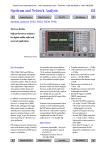
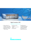
Specifications
FSEA30
FSEB30
FSEM30
FSEK30
Specifications are guaranteed under the following conditions:
30 minutes warmup time at ambient temperature, specified environmental conditions met, calibration cycle adhered to, and total calibration performed.
Data without tolerances: typical values only. Data designated "nominal" apply to design parameters and are not tested.
Frequency
Frequency range
Frequency resolution
Internal reference frequency, nominal
Aging per day1)
Aging per year1)
Temperature drift (0°C to +50°C)
Total error limit (per year)
External reference frequency
Frequency display
Resolution
Error limit (sweep time >3 × auto sweep time)
Frequency counter
Resolution
Count accuracy (S/N >25 dB)
Display range for frequency axis
Resolution/error limit of display range
Spectral purity (dBc (Hz))
SSB phase noise, f ≤500 MHz
Carrier offset
100 Hz
1 kHz
10 kHz
100 kHz2)
1 MHz 2)
Sweep time
Span = 0 Hz
Span ≥10 Hz
Error limit
Picture refresh rate (span ≤7 GHz)
Sampling rate
Number of pixels
Time measurement
Resolution
Sweep trigger
Zero span
Resolution bandwidths
3 dB bandwidths (in 1/2/3/5 steps)
FFT filter (in 1/2/3/5 steps) (see also page 16)
20 Hz to 3.5 GHz
20 Hz to 7 GHz
20 Hz to 26.5 GHz
0.01 Hz
20 Hz to 40 GHz
1x10⁻⁹
2 x10⁻⁷
5 x10⁻⁸
2.5 x10⁻⁷
10 MHz or n × 1 MHz, n = 1 to 16
with marker
0.1 Hz to 10 kHz (as a function of span)
±(marker frequency × reference error + 0.5 % × span + 10 % × resolution bandwidth + 1/2 (last digit))
measures the marker frequency
0.1 Hz to 10 kHz (selectable)
±(frequency × reference error + 1/2 (last digit))
0 Hz, 10 Hz to full span
0.1 Hz/1%
for f >500 MHz see diagram below
<–87
<–107
<–120
<–119
<–138
<–81
<–100
<–114
<–113
<–132
1 µs to 2500 s in 5% steps
5 ms to 16 000 s in steps ≤10%
<1%
>20 updates/s with 1 trace, >15 updates/s with 2 traces
50 ns (20 MHz A/D converter)
500
with marker and cursor lines
50 ns
free run, single, line, video, gated, delayed, external
additionally pretrigger, posttrigger, trigger delay
1 Hz to 10 MHz
1 Hz to 1 kHz
–60
dBc (Hz)
–70
FSEA 500 MHz
FSEA 3.5 GHz
FSEB/M/K 500 MHz
FSEB/M/K 3.5 GHz
FSEM/K 26 GHz
FSEK 40 GHz
–80
SSB phase noise
–90
–100
–110
–120
–130
–140
–150
–155
100 Hz
SSB phase noise (typical values)
12
Spectrum Analyzers FSEx
1 kHz
10 kHz
100 kHz
1 MHz
Carrier offset
10 MHz
Specifications
FSEA30
FSEB30
≤3 MHz
5 MHz
10 MHz
Shape factor 60:3 dB <1 kHz
1 kHz to 2 MHz
>2 MHz
Video bandwidths
Bandwidth error
FSEM30
<10%
<15%
+25%, –10%
<6
<12
<7
1 Hz to 10 MHz, 1/2/3/5 steps
FSEK30
Level
Display range
Maximum input level
RF attenuation 0 dB
DC voltage
CW RF power
Pulse spectral density
RF attenuation ≥10 dB
DC voltage
CW RF power
Max. pulse voltage
Max. pulse energy (10 µs)
1 dB compression of input mixer
(0 dB RF attenuation)
Displayed average noise floor
Frequency
20 Hz
1 kHz
10 kHz
100 kHz
1 MHz
10 MHz to 3.5/6 GHz
6 GHz to 7 GHz
7 GHz to 18 GHz
18 GHz to 26.5 GHz
26.5 GHz to 30 GHz
30 GHz to 40 GHz
Max. dynamic range, bandwidth 1 Hz
Displayed noise floor to 1 dB compression
Max. harmonics suppression, f >50 MHz
Max. intermodulation-free range
50 MHz to 3.5 GHz (nominal)
150 MHz to 7/26.5 GHz (nominal)
Intermodulation
TOI, intermodulation-free dynamic range,
level 2 × −30 dBm, ∆f >5 × RBW or >10 kHz
Intermodulation-free range at –40 dBm mixer level
Intercept point k2 (dBm)
noise floor displayed to 30 dBm
0V
20 dBm (=0.1 W)
97 dBµV (MHz)
0V
30 dBm (=1W)
150 V
1mWs
+10 dBm nominal
in dBm (0 dB RF attenuation, RBW 10 Hz, VBW 1 Hz, 20 averages, trace average, span 0 Hz, termination 50 Ω)
<–80
<–74
<–110
<–104
<–125
<–119
<–135
<–129
<–145, –150 typ.
<–142, typ. –145
<–145, –150 typ.
<–142, –147 typ.
<–138, –140 typ.
–
<–139
<–135, –138 typ.
–
–
<–138, –140 typ.
<–134, –139 typ.
–
–
<–135, –138 typ.
<–131, –136 typ.
–
–
–
<–120, –125 typ.
–
–
–
<–116, –122 typ.
165 dB
162 dB
160 dB
>90 dB
115 dB
–
–
115 dB
>84 dBc for f >50 MHz
(TOI >12 dBm,
18 dBm typ. )
>90 dBc for f >150 MHz
(TOI >15 dBm,
20 dBm typ. )
>25, >40 typ. for
f <50 MHz, >45,
>50 typ. for f >50 MHz
Immunity to interference
Image frequency (dB)
Intermediate frequency (dB)
Spurious response (f >1 MHz, without input signal,
0 dB attenuation)
Span <30 MHz
Span ≥30 MHz
fin = 25.06 MHz, 25.175 MHz, 5.7172 GHz
fin = 60 MHz
fin = 14.1894 GHz, 15.6722 GHz
Span >10 MHz
Other interfering signals (mixer level <–10 dBm)
50 V
0.5 mWs
–
112 dB
>94 dBc for f >100 MHz
>80 dBc for f >7 GHz,
(TOI >17 dBm, 22 dBm typ.;
>10 dBm for f >7 GHz)
105 dB
>25 for f <150 MHz, >35 typ.,
>40 for f >150 MHz, >45 typ.
>80, >90 typ.
>80, >90 typ. for f <22 GHz
>75, >80 typ. for f >22 GHz
>75 dB
>100 dB
<–110 dBm
<–100 dBm
<–100 dBm
<–110 dBm
<–100 dBm
−90 dBm
<–80 dB3)
<–75 dB 3)
Spectrum Analyzers FSEx
13
Specifications
FSEA30
Level display
Measurement display
Logarithmic level range
Linear level range
Traces
Trace detector
Trace functions
Setting range of reference level
Logarithmic level display
Linear level range
Units of level axis
Level measurement uncertainty (–40 dBm, RF attenuation 20 dB, reference level –15 dB, RBW 5 kHz)
Absolute error limit at 120 MHz
Frequency response (10 dB RF attenuation)
<1 GHz
1 GHz to 3.5/7 GHz
7 GHz to 18 GHz
18 GHz to 26.5 GHz
26.5 GHz to 40 GHz
Attenuator error limit
IF gain error
Display nonlinearity
Logarithmic level display
(RBW ≥1 kHz, analog)
0 dB to –50 dB
–50 dB to –70 dB
–70 dB to –80 dB
–70 dB to –95 dB
Linear level display
Bandwidth switching error
1 Hz to 30 kHz/100 to 500 kHz
1 MHz to 10 MHz
Total measurement uncertainty (0 dB to 50 dB below
reference level, span/RBW <100, rss 95% reliability)
<1 GHz
1 GHz to 3.5/7 GHz
7 GHz to 18 GHz
18 GHz to 26.5 GHz
26.5 GHz to 40 GHz
Pulse amplitude error (single pulses)
Bandwidth <1 MHz/≥1 MHz
FSEB30
FSEM30
FSEK30
500 × 400 pixels (with one diagram displayed); max. 2 diagrams with independent settings
10 dB to 200 dB, in steps of 10 dB
10% of reference level per division (10 divisions) or logarithmic scaling
max. 4 per diagram (max. 2 if 2 diagrams are displayed)
quasi-analog display of all results
max peak, min peak, auto peak (normal), sample, rms, average
clear/write, max hold, min hold, average
–130 dBm to 30 dBm, in steps of 0.1 dB
7.0 nV to 7.07 V in steps of 1%
dBm, dBµV, dBmV, dBµA, dBpW (logarithmic and linear level display);
mV, µV, mA, µA, pW, nW (linear level display)
The values are guaranteed for bandwidths from 10 Hz to 30 kHz and 100 kHz to 10 MHz.
<0.3 dB
<0.5 dB
<1 dB
–
–
–
–
<0.3 dB
<0.2 dB (0.1 dB typ.)
<2 dB4)
<2.5 dB4)
<3 dB4)
<0.3 dB
<0.5 dB
–
<1 dB
5% of reference level
<0.2 dB
<0.3 dB
<1 dB
<1.5 dB
–
–
–
–
<2.5 dB4)
<3 dB4)
<3.5 dB4)
<0.5 dB, nominal/<2 dB, nominal
Trigger functions
Trigger
Delayed sweep
Trigger source
Delay time
Error of delay time
Delayed sweep time
Gated sweep
Trigger source
Gate delay
Gate length
Error of gate length
Gap sweep (span = 0 Hz)
Trigger source
Pretrigger
Trigger to gap time
Gap length
14
Spectrum Analyzers FSEx
free run, line, video, RF, external
free run, line, video, RF, external
100 ns to 10 s, resolution 1 µs min. or 1% of delay time
±(1 µs + (0.1% x delay time))
2 µs to 1000 s
external, RF level
1 µs to 100 s
1 µs to 100 s, resolution min. 1 µs or 1% of gate length
±(1 µs + (0.05% × gate length))
free run, line, video, RF, external
1 µs to 100 s, 50 ns resolution, dependent on sweep time
1 µs to 100 s, 50 ns resolution, dependent on sweep time
1 µs to 100 s, 50 ns resolution
Specifications
FSEA30
FSEB30
FSEM30
FSEK30
Audio demodulation
AF demodulation types
Audio output
Marker stop time
AM and FM
loudspeaker and headphones output
100 ms to 60 s
Inputs and outputs (front panel)
RF input
VSWR (RF attenuation ≥10 dB)
f <3.5 GHz
f <7 GHz
–
f <26.5 GHz
f <37 GHz
f <40 GHz
Attenuator
Probe power
Power supply and coding connector for antennas etc
(antenna code)
Supply voltages
AF output
Open-circuit voltage
N female, 50 Ω
adapter system, 50 Ω, N adapter system, 50 Ω,
male and female, 3.5 mm N male and female, K
male and female
male and female, 2.4 mm
female
<1.5
–
–
–
<2.0
<3
–
–
0 dB to 70 dB, selectable in 10 dB steps
+15 V DC, –12.6 V DC and ground, max. 150 mA
12-contact Tuchel
<2.5
<2.5
2.5 typ.
±10 V, max. 100 mA, ground
Zout = 10 Ω , jack plug
adjustable up to 1.5 V
Inputs and outputs (rear panel)
IF 21.4 MHz
Level
Video output
Voltage (resolution bandwidth ≥1 kHz)
Reference frequency
Output, usable as input
Output frequency
Level
Input
Required level
Sweep output
Power supply connector for noise source
External trigger/gate input
Voltage
IEC/IEEE-bus control
Connector
Interface functions
Serial interface
Mouse interface
Plotter5)
Printer interface
Keyboard connector
User interface
Connector for external monitor (VGA)
Zout = 50 Ω , BNC female, bandwidth >1 kHz or resolution bandwidth
0 dBm at reference level, mixer level > –60 dBm
Zout = 50 Ω , BNC female
0 V to 1 V, full scale (open-circuit voltage); logarithmic scaling
BNC female
10 MHz
10 dBm nominal
1 MHz to 16 MHz, integer MHz
>0 dBm into 50 Ω
BNC female, 0 V to 10 V in sweep range
BNC female, 0 V and 28 V, selectable
BNC female, >10 kΩ
–5 V to +5 V, adjustable
interface to IEC625-2 (IEEE 488.2), command set: SCPI 1994.0
24-contact Amphenol female
SH1, AH1, T6, L4, SR1, RL1, PP1, DC1, DT1, C11
RS-232-C (COM 1 and COM 2), 9-contact female connectors
PS/2 mouse compatible
via IEC/IEEE bus or RS-232-C; plotter language: HP-GL
parallel (Centronics compatible) or serial (RS-232-C)
5-contact DIN female for MF-2 keyboard
25-contact Cannon female
15-contact female
General data
Display
Resolution
Pixel failure rate
Mass memory
Operating temperature range
Nominal temperature range
Limit temperature range
Storage temperature range
Humidity
Mechanical resistance
Vibration, sinusoidal
Vibration, random
24 cm LC TFT colour display (9.5")
640 × 480 pixels (VGA resolution)
<2 x 10⁻⁵
1.44 Mbyte 3 ½" diskette drive, hard disk
+5°C to +40°C
0°C to +50°C
–40°C to +70°C
+40°C at 95 % relative humidity (IEC68-2-3)
5 Hz to 150 Hz, max. 2 g at 55 Hz; 55 Hz to 150 Hz, 0.5 g const.
to IEC68-2-6, IEC68-2-3, IEC1010-1, MIL-T-28800D, class 5
10 Hz to 300 Hz, acceleration 1.2 g (rms)
Spectrum Analyzers FSEx
15
Specifications
FSEA30
Shock
Recommended calibration interval
RFI suppression
Power supply
AC supply
Power consumption
Safety
Test mark
Dimensions in mm (W x H x D)
Weight in kg
1)
2)
3)
4)
5)
FSEB30
FSEM30
FSEK30
40 g shock spectrum, to MIL-STD-810 D and MIL-T-28800 D, classes 3 and 5
1 year (2 years for operation with external reference)
to EMC directive of EU (89/336/EEC) and German EMC legislation
200 V to 240 V: 50 Hz to 60 Hz, 100 V to 120 V: 50 Hz to 400 Hz, class of protection I to VDE 411
180 VA
195 VA
230 VA
230 VA
to EN61010-1, UL3111-1, CSA C22.2 No. 1010-1, IEC1010-1
VDE, GS, UL, cUL
435 x 236 x 460 (5 HU)
435 x 236 x 570
435 x 236 x 570
22.7
23.2
25.2
25.8
After 30 days of operation.
Valid for span >100 kHz.
For models with option FSE-B23: <–50 dBm.
For frequencies >7 GHz: error after calling peaking function. For sweep times <10 ms/GHz: additional error 1.5 dB.
The plot function is not available if option FSE-B15 is installed.
Specifications
External Mixing FSE-B21
FFT filter
High frequency resolution due to very small shape factor of 2.5
Extremely short measurement time, up to 150 times faster than with conventional
filters
Resolution bandwidths (RBW)
3 dB bandwidth
in 1/2/3/5 steps
Bandwidth error
Shape factor 60:3 dB
1 Hz to 1 kHz
2%, nominal
2.5, nominal
LO output/IF input (front panel)
LO signal
Amplitude
IF signal
Full-scale level
IF input (front panel)
IF signal
Full-scale level
Level measurement error at IF inputs
(IF level –30 dBm,
reference level –20 dBm, RBW 30 kHz)
SMA female, 50 Ω
7.5 GHz to 15.2 GHz
+15.5 dBm ±3 dB
741.4 MHz
–20 dBm
SMA female, 50 Ω
741.4 MHz
–20 dBm
<1 dB
Increased Level Accuracy FSE-B22
Display range for frequency axis
Min. span
Max. span
25 x RBW
100000 x RBW, max. 2 MHz
Sweep time for 10 kHz Span
100 000
Specifications are valid for:
Temperature range
Frequency range
Resolution bandwidths
Signal level
Stop frequency
Sweep time
FFT filter
10 000
1000
Analog filter
100
Sweep time in s
≤0.5 dB with 10 dB RF attenuation
≤0.6 dB with 20/30/40 dB RF attenuation
Total level error
10
1
0,1
-/+20°C to +30°C
10 MHz to 2 GHz
5 kHz to 30 kHz/300 kHz/1 MHz
10 dB to 50 dB below reference level
≤2 GHz
≥3 x auto sweep time
0,01
1
3
10
30
100
300
RBW in Hz
Level measurement error
Additional total level error,
referred to RBW 5 kHz
<1 dB
Max. display range
100 dB
Immunity to interference
Spurious response
≤100 dBm
FSE-B23 reduces the suppression of other interference signals to –50 dBm and
must not be combined with FSE-K10/-K11.
Gain from RF input to
IF output (dB)
3 dB BW (MHz)
1 dB Attenuator FSE-B13
Frequency range
Setting range of RF attenuation
Step width
Additional attenuator uncertainty
Broadband Output 741.4 MHz FSE-B23
max. 7 GHz (stop frequency ≤7 GHz)
0 dB to 70 dB
1 dB
<0.1 dB
1)
2)
3)
FSEA
FSEB
FSEM
FSEK
6
6
4
4
60
150
1501)
40 to 802)
1501)
40 to 1203)
f <7 GHz.
7 GHz to 26.5 GHz.
7 GHz to 40 GHz.
Spectrum Analyzers FSEx
16
Connector
Impedance
BNC
50 Ω
For maximum bandwidth set instrument to 10 MHz RBW. The output level is a
function of the mixer level, which equals the input signal level minus the set RF
attenuation.
The typical loss between mixer level and IF output is 2 dB for FSEM/K, and 0 dB
for FSEA/B.
44 GHz Frequency Extension for FSEK FSE-B24
Frequency range
20 Hz to 44 GHz
Level
Displayed average noise level (DANL)
(0 dB RF attenuation, RBW = 10 Hz, VBW = 1 Hz, 20 averages, trace average,
span 0 Hz, 50 Ω termination)
40 GHz to 42 GHz
<–112, –128 dBm typ.
42 GHz to 43 GHz
<–108, –113 dBm typ.
43 GHz to 44 GHz
<–105, –110 dBm typ.
Intermodulation
3rd-order intercept point (TOI) ∆ f >5 x resolution bandwidth or >10 kHz
>40 GHz
+15 dBm typ.
2nd harmonic intercept point (SHI)
>25 dBm for f <150 MHz
>40 dBm for f >150 MHz
Level measurement error
Frequency response (10 dB RF attenuation)
40 GHz to 44 GHz
<4.0 dB1)2)
Total measurement error
(0 dB to 50 dB below reference level)
40 GHz to 44 GHz
<4.5 dB1)2)
Inputs and outputs (front panel)
RF input
VSWR (RF attenuation >0 dB)
f >40 GHz
1)
2)
Ordering information
adapter system, 50 Ω, N male und
female, K male und female, 2.4 mm
female
<3.0:1 typ.
Error after running the preselector peaking function. For sweep <10 ms/GHz: additional error
1.5 dB.
Temperature range 20°C to 35°C.
Order designation
Type
Order No.
Removable Hard Disk
FSE-B184)
1088.6993.02
Order designation
Type
Order No.
Spectrum Analyzer 20 Hz to 3.5 GHz
FSEA30
1065.6000.35
2nd Hard Disk for FSE-B18
(firmware included)
FSE-B19
1088.7248.02
Spectrum Analyzer 20 Hz to 7 GHz
FSEB30
1066.3010.35
External Mixing
FSE-B21
1084.7243.02
Spectrum Analyzer 20 Hz to 26.5 GHz
FSEM30
1079.8500.35
Increased Level Accuracy up to 2 GHz
FSE-B224)
Spectrum Analyzer 20 Hz to 40 GHz
FSEK30
1088.3494.35
Accessories supplied
Power cable, operating manual, spare fuses;
FSEM: test-port adapter 3.5 mm female (1021.0512.00) and N female
(1021.0535.00)
FSEK: test-port adapter K female (1036.4790.00) and N female (1036.4777.00)
Options (see also fold-in page)
FSE-B23 )
1088.7348.02
44 GHz Frequency Extension for FSEK
FSE-B244)
1106.3680.02
FS-K31)
1057.3028.02
Software
Noise Measurement Software, Windows
Phase Noise Measurement Software, Windows FS-K4 )
FSE-B2
1073.5044.02
Vector Signal Analyzer
FSE-B71)
1066.4317.03
1
FSE-B8 )
1066.4469.02
3.5 GHz with I/Q modulator FSE-B91)
1066.4617.02
1
1106.3480.02
Broadband Output 741.4 MHz
1
7 GHz Frequency Extension for FSEA
Tracking Generator 3.5 GHz
4
GSM Application Firmware
Mobile station
Base station
EDGE Application Firmware Mobile station
Base station
1108.0088.02
FSE-K101)
1
1057.3092.02
FSE-K11 )
1057.3392.02
FSE-K201)
1106.4086.02
1
FSE-K21 )
1106.4186.02
FSE-Z1
1066.3862.02
5 MHz to 7000 MHz (type N)
FSE-Z3
4010.3895.00
10 kHz to 18 GHz (type N)
FSE-Z4
1084.7443.02
7 GHz
FSE-B10 )
1066.4769.02
Recommended extras
7 GHz with I/Q modulator
FSE-B111)
1066.4917.02
Service Kit
Switchable Attenuator for Tracking Generator
2)
FSE-B12
1066.5065.02
DC Block
1 dB Attenuator
FSE-B132)3) 1119.6499.02
Controller for FSE (mouse and keyboard
included)
FSE-B154)
1073.5696.06
Microwave Measurement Cable and Adapter
Set for FSEM
FSE-Z15
1046.2002.02
Ethernet Interface 15-contact AUI connector
FSE-B165)
1073.5973.02
Harmonic Mixer
FS-Z601)
1089.0799.02
FSE-B165)
1073.5973.03
50 GHz to 75 GHz
FS-Z75 )
1089.0847.02
RJ-45 connector (twisted pair) FSE-B16 )
1073.5973.04
60 GHZ to 90 GHz
FS-Z901)
1089.0899.02
FSE-B175)
1066.4017.02
1
1089.0976.00
Thin-wire BNC connector
5
2nd IEC/IEEE-Bus Interface for FSE
40 GHz to 60 GHz
75 GHZ to 110 GHz
1
FS-Z110 )
Spectrum Analyzers FSEx
17
Order No.
Order designation
Service Manual
–
1065.6016.24
High-Power Attenuators
Headphones
–
0708.9010.00
German
PSA-Z2
1007.3001.31
US
PSA-Z2
1007.3001.02
FSE-Z2
1084.7043.02
1m
PCK
0292.2013.10
2m
PCK
0292.2013.20
19" Rack Adapter, with front handles
ZZA-95
0396.4911.00
Transit Case
ZZK-954
1013.9395.00
Transit Case (FSEM30 and FSEK30 only)
ZZK-955
1013.9408.00
Matching Pads, 75 Ω L section
RAM
0358.5414.02
RAZ
0358.5714.02
Keyboard
PS/2 Mouse
IEC/IEEE-Bus Cable
Series resistor, 25 Ω
SWR Bridge
5 MHz to 3000 MHz
ZRB2
0373.9017.52
40 kHz to 4 GHz
ZRC
1039.9492.52
Order No.
RBU 100
RBU 50
1073.8820.xx
1073.8895.xx
xx: 03/06/10/
20/30
ESV-Z3
0397.7014.52
–
1021.0541.00
–
1021.0529.00
–
1036.4783.00
K male
–
1036.4802.00
2.4 mm female
FSE-Z5
1088.1627.02
–
1065.9480.00
100 W
50 W
Steps: 3/6/10/20/30 dB
For FSEM only:
Test-Port Adapter
N male
3.5 mm male
For FSEK only:
Test-Port Adapter
N male
Probe Power Connectors 3-contact
1)
2)
3)
4)
5)
Extra data sheets available.
FSE-B12 and FSE-B13 cannot be fitted together.
In combination with FSE-B22 factory-fitted only.
Cannot be retrofitted, factory-fitted only.
FSE-B16 and FSE-B17 require option FSE-B15.
PD 0757.1519.28 ⋅ Spectrum Analyzers FSEx ⋅ Trade names are trademarks of the owners ⋅ Subject to change ⋅ Data without tolerances: typical values
Accessories for current, voltage and fieldstrength measurement
see accessories for Test
Receiver and Spectrum
Analyzers, data sheet
PD 0756.4320
Type
0501 (Bi ko)
Type
Printed in Germany
Order designation
ROHDE&SCHWARZ GmbH & Co. KG ⋅ Mühldorfstraße 15 ⋅ 81671 München ⋅ Germany ⋅ P.O.B. 8014 69 ⋅ 81614 München ⋅ Germany ⋅ Telephone +49894129-0
www.rohde-schwarz.com ⋅ Customer Support: Tel. +491805124242, Fax +4989 4129-13777, E-mail: [email protected]