1
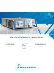
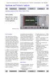
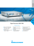
NEW
up to 25 dBm
RF sweep
9 kHz to 1040/2080 MHz
Signal Generators SMY
Versatility and low cost can go hand in hand
• Frequency resolution 1 Hz
• Level range −140 to +19 dBm,
overrange up to 25 dBm (option)
• Level accuracy better than 1 dB
• SSB phase noise <−114 dBc at
1 GHz, ∆f = 20 kHz
• AM, FM, ϕM and pulse
modulation
• Modulation generator 1 Hz to
500 kHz
• Sweep capabilities
• Nonvolatile memory for
100 complete front-panel setups
• RF overload protection 30 W
(SMY01) or 50 W (SMY02)
• Low RF leakage (<0.1 µV)
• Calibration at 3-year interval
SMY – the ideal generator for
receiver measurements ...
• Level range −140 dBm to +13 dBm
(19 dBm overrange) *), sufficient
even for receivers of highest sensitivity
spurious rejection for all in-channel
and blocking measurements
Signal generators of the SMY family from
• High level accuracy and low RF leakage allowing accurate and unde-
• Low residual FM affording ample of
margin for S/N measurements
graded sensitivity measurements
• FM-DC with high accuracy of car-
• Modulation generator 1 Hz to
500 kHz for modulation frequency
Rohde&Schwarz are cost-effective
instruments for testing AM, FM and ϕM
receivers as well as for component measurements. Two models are available:
rier frequency for testing pagers
and receivers fitted with digital squel-
• SMY01 with a frequency range
from 9 kHz to 1040 MHz
ches
• Low SSB phase noise and high
response measurements
• Stereo channel separation of 50 dB
and low harmonic distortion for
testing FM stereo receivers
• SMY02 from 9 kHz to 2080 MHz.
Designed exclusively for the main ap-
... and for general-purpose applications
plications of signal generators by cutting out the unnecessaries, SMY features an outstanding price/performance ratio. Thanks to its comprehensive basic features and excellent signal
characteristics, it is an economical solution for universal use in lab, production and servicing environments.
*) With option SMY-B40 −134 dBm to +19 dBm
(25 dBm overrange)
2
Signal Generators SMY
Thanks to the excellent
spectral purity and the
high accuracy of the
carrier frequency with
FM-DC, measurements
on steep-edged crystal
filters are possible without any problem.
Certified Quality System
ISO 9001
DQS REG. NO 1954-04
With option SMY-B40:
The overrange feature
for the output level
allows measurements
on high-level mixers. To
the right: output level obtained with settings of
19 dBm, 21 dBm,
23 dBm and 25 dBm
25 dBm
23 dBm
21 dBm
19 dBm
Accuracy of carrier
frequency with FM-DC,
long-term stability.
Settings: carrier
frequency = 1 GHz,
FM deviation = 50 kHz,
external FM-DC
• Non-interrupting level setting over a
range of 20 dB for reproducible
measurement of squelch hysteresis
• Frequency resolution 1 Hz, suitable
also for narrowband test items
• FM-DC, deviation up to 20 MHz for
VCO simulation
• FM bandwidth 2 MHz for fast FSK
and telemetry applications
FM frequency
response of SMY.
Frequency modulation
is possible even at full
deviation up to high modulation frequencies
• High output level up to 19 dBm
(25 dBm with option SMY-B40) for
component and overdrive testing
• AF synthesizer 1 Hz to 500 kHz,
separate use as AF signal source for
external applications possible, eg
recording of AF frequency response
• Remote-control interface IEC625/
IEEE488 for use in automatic test
systems
Level/frequency
response at 0 dBm
output level. The software-supported level
correction reduces the
frequency response to
typically 0.1 dB
• RF sweep
• Sequence function and SEQ input
for semi-automatic use
Phase-continuous
frequency change of
modulation generator.
To the right:
frequency change from
10 Hz to 40 Hz
Signal Generators SMY
3
Cost-saving synthesis concept
measuring instrument and the signal
gned for maximum stability, calibration
is required at intervals of 3 years only.
Single-loop synthesis is a concept that
generator can be dispensed with. Naturally fast tuning and programming of
makes for simple and cost-effective circuit design and does not entail giving
the step width are also possible.
If the accuracy is required to be higher
than the specified data, user-specific
up high frequency resolution and short
setting time. The fractional-N technique
Frequently used settings can be stored
and recalled any time. The memory
calibration values for frequency and
level may be entered and stored at any
uses a fractional frequency division
ratio, ie a frequency resolution of 1 Hz
saves up to 100 complete front-panel
setups.
time without opening the instrument.
is obtained in spite of the high reference
frequency. High reliability and light
weight thanks to VLSI components are
further advantages of this technique.
Low cost of ownership thanks to
high reliability and easy
maintenance
Further development of proven
technology
Signal Generators SMY from Rohde &
Schwarz stands for the economy class
Operation
Like with all Rohde & Schwarz signal
generators, the well-proven self-test faci-
of generators. Well-proven features
have been improved and unnecessary
The panel controls are ergonomically
arranged so that there is no time wasted
lity is integrated in SMY monitoring continuously the signal generator status. If
details omitted. It is the sum of its characteristics which makes SMY so attractive.
for familiarization. Operation is from
the left to the right: parameters, data,
there are any malfunctions, these are
immediately detected and reported in
Tangible for the user are the variety of
facilities and versatility at an excellent
units; each control is at its right place.
the form of error messages. The user
thus has an effective protection against
price/performance ratio. SMY is the
economical solution for universal use in
The patented, magnetically locking
spinwheel is just as practical. Although
invalid measurements, should the generator ever fail.
lab, production and servicing environments.
easy to turn, each setting step is felt exactly by the user. Thus for instance it is not
Thanks to its advanced circuit design,
really necessary to observe the SMY display in the case of stepwise tuning. This
SMY requires particularly little maintenance. Aging and drift are compensa-
means that the annoying procedure of
looking back and forth between a
ted for by control loops. Due to the few
reference components, which are desi-
Rear-panel of SMY
Signal Generators SMY
4
Simultaneous modulation
Specifications
Frequency
Range
Underranging
without guarantee of specs
Resolution
Setting time (to within
<1 x 10⁻⁷ for f >65 MHz or
<70 Hz for f <65 MHz)
Reference frequency
Aging (after 30 days of operation)
Temperature effect (0 to 55 °C)
Warmup time
Output for internal reference
Frequency
Level (EMF, sinewave)
Source impedance
Input for external reference
Frequency
Input level
Input impedance
Spectral purity
Spurious
Harmonics
Subharmonics
f ≤1.04 GHz
f >1.04 GHz
Nonharmonics
at >5 kHz from carrier
f ≤1.04 GHz
f >1.04 GHz
Broadband noise with CW 1),
carrier offset >1 MHz,
1 Hz bandwidth
f = 1 to 65 MHz
f >65 MHz
SSB phase noise at
20 kHz from carrier,
1 Hz bandwidth, CW
f <65 MHz
100 MHz
500 MHz
1 GHz
2 GHz
Residual FM, rms, <1% of
maximum deviation, f =1 GHz
0.3 to 3 kHz (CCITT)
0.03 to 20 kHz
Residual AM, rms (0.03 to 20 kHz)1)
Level
Range
Overranging
without guarantee of specs
Resolution
Total error for levels >−127dBm 1)
f <1.04 GHz
f >1.04 GHz
Level flatness at 0 dBm 1)
Output impedance
VSWR 1)
Setting time (IEC/IEEE bus)
Non-interrupting level setting
(ATTENUATOR MODE FIXED)
Setting range
Overload protection
Max. RF power
SMY 01
SMY 02
Max. DC voltage
Max. pulse loading capacity
(pulse width <10 µs)
9 kHz to 1.04 GHz (SMY 01)
9 kHz to 2.08 GHz (SMY02)
down to 5 kHz
1 Hz
Setting error at 1 kHz (m <80%)1)
<60 ms
standard
1 x 10⁻⁶/year
2 x 10⁻⁶
–
option SMY-B1
<1 x 10⁻⁹/day
<5 x 10⁻⁸
10 min
10 MHz
1 V (rms)
50 Ω
5 or 10 MHz ±5 x 10⁻⁶
0.2 to 2 V (rms)
200 Ω
standard
option SMY-B40
<−30 dBc for
levels <10 dBm
<−25 dBc for
levels <16 dBm
none
<−40 dBc
<−70 dBc
<−64 dBc
<−135 dBc
<−140 dBc
<−114
<−132
<−120
<−114
<−108
dBc
dBc
dBc
dBc
dBc
<10 Hz, typ. 3 Hz
<20 Hz, typ. 7 Hz
<0.02%
standard
option SMY-B40
−140 to +13 dBm −134 to +19 dBm
up to 19 dBm
Amplitude modulation
Modes
Modulation depth
Resolution
up to 25 dBm,
down to −140 dBm
0.1 dB
AM distortion at 1 kHz1)
f <10 MHz
m= 30%
m=80%
f >10 MHz
m=30%
m=80%
Modulation frequency response
flatness (m=60%) 1) 3)
30 Hz (DC) to 10 kHz
10 Hz (DC) to 50 kHz
Incidental ϕM with AM (30%),
AF = 1 kHz
Modulation input (AM EXT)
Input impedance
Input voltage for selected
modulation depth
Frequency modulation
Modes
Maximum deviation for
carrier frequency
<65 MHz
65 to 130 MHz
130 to 260 MHz
260 to 520 MHz
520 to 1040 MHz
1040 to 2080 MHz
Resolution
Setting error at AF = 1 kHz
FM distortion at AF = 1 kHz
and 3% of maximum deviation
Modulation frequency response
flatness
10 Hz (DC) to 2 MHz
Incidental AM at AF = 1 kHz,
f >1 MHz, 40 kHz deviation
Stereo modulation at 40 kHz
deviation, AF = 1 kHz
Stereo separation4)
S/N ratio
unweighted
weighted
Harmonic distortion
Carrier frequency offset
with FM-DC4)
Modulation input
Input impedance
Input voltage for selected
deviation
<±1 dB
<±1.5 dB
<1 dB, typ. <0.3 dB
50 Ω
<1.5 for f ≤1.04 GHz
<1.8 for f >1.04 GHz
<25 ms (<10 ms with electronic
level setting)
any combination of AM, FM (ϕM) and
pulse modulation
internal, external AC/DC
0 to 100%2)
0.1%
standard
option SMY-B40
<4% of
<4% of
reading ±1%
reading ±3%
<1%
<2%
<3%
<5%
<1%
<2%
<1%
<2%
<0.4 dB
<3 dB
<0.2 rad
<0.4 rad at f >1.04 GHz (SMY02)
100 kΩ; 600 Ω jumper-selected
1 V (peak) (for inaccuracy >3%:
high/low indication)
internal, external AC/DC
10 MHz
1.25 MHz
2.5 MHz
5 MHz
10 MHz
20 MHz
<1%, min. 10 Hz
<3% of reading + 20 Hz
<0.3%, typ. 0.1%
<3 dB, typ. 1 dB
<0.1%
>50 dB
>76 dB
>70 dB
typ. 0.1%
<1 Hz + 0.1% of deviation
FM/ϕM EXT
100 kΩ; 600 Ω jumper-selected
1 V (peak) (for inaccuracy >3%:
high/low indication for
AF = 10 Hz to 100 kHz)
0 to −20 dB
protects the instrument against externally applied (50-Ω source) RF power
and DC voltage
30 W
50 W
35 V
1 mWs or 150 V (Vp)
SSB phase noise at 1 GHz (CW)
Signal Generators SMY
5
Pulse modulation
Mode
On/off ratio
standard
external
>80 dB
option SMY-B40
external
>70 dB at 70 MHz,
linearly decreasing to
>65 dB at 520 MHz,
>65 dB at 800 MHz,
linearly decreasing to
>35 dB at 2080 MHz
typ. 4 µs
<20 ns
typ. 3.5 µs <200 ns
BLANK
PULSE
10 kΩ
10 kΩ
TTL/HC logic signal, polarity selectable
TTL/HC logic signal, RF ON at high,
RF ON at low jumper-selected
Rise/fall time (10/90%)
Pulse delay
Modulation input
Input impedance
Input level, standard
Input level, option SMY-B40
Internal modulation generator
Frequency range
Resolution
Display
Frequency error
Frequency response flatness
up to 50 kHz
up to 100 kHz
1 Hz to 500 kHz
0.1 Hz
7 digits, floating point
<5 x 10⁻⁵
<0.2 dB
<0.3 dB
%
0.01
20
50
100
200
500
1k
2k
5k
10 k 20 k 50 k 100 k
Typical harmonic distortion of AF synthesizer as a function of frequency
THD (20 Hz to 100 kHz)
Output voltage
Frequency setting time
Temperature range
Guaranteed specs
Storage temperature
Climatic conditions
Humidity
Mechanical resistance
Sinewave vibration
Electromagnetic compatibility
RF leakage
Radiated susceptibility
0 to 55 °C; complying with
IEC68-2-1 and IEC68-2-2
−40 to +70 °C
95% relative humidity at +40 °C;
complying with IEC68-2-3
5 to 150 Hz, max. 2 g at 55 Hz, max.
0.5 g in range 55 to 150 Hz, complying with IEC68-2-6, IEC1010-1 and
MIL-T-28800D, class 5
complying with EN50081-1 and
EN50082-1 (EMC Directives of EU)
<0.1 µV (measured with a two-turn coil
of 2.5 cm in diameter at a distance of
2.5 cm from any point of enclosure)
10 V/m
Power supply
100 V/230 V (AC) −10 to +15%,
120 V/220 V (AC) −12.5 to +10%,
47 to 440 Hz, max. 120 VA
Safety
complying with EN 61010-1
Dimensions (W x H x D)
SMY01
SMY02
435 mm x 147 mm x 350 mm
435 mm x 147 mm x 460 mm
Weight
12 kg (SMY01), 13 kg (SMY02)
<0.1%
1 V (peak) ±1%
(Rout <10 Ω, RL >200 Ω)
<10 ms (after receiving last IEC/IEEEbus character)
RF sweep
Mode
Sweep range and step width
Step duration
Resolution
digital sweep in discrete steps
automatic, linear
user-selected
10 ms to 5 s
1 ms
Memory
non-volatile, for 100 instrument setups
Signal Generator
SMY01
SMY02
Accessories supplied
power cord, operating manual
Options
Reference Oscillator OCXO
SMY-B1
Rear-Panel Connectors for RF and NF SMY-B10
Pulse Modulator and
SMY-B40
High Output Power5)
Recommended extras
19" Rack Adapter
Service Kit
Service Manual
1)
2)
3)
4)
5)
Printed in Germany
General data
1197 (Pe we)
IEC 625 (IEEE 488)
Amphenol, 24-contact
0 to 30
SH1/AH1/T6/L4/SR1/RL1/PP0/
DC1/DT0/C0
Ordering information
0.1
f [Hz] 10
Remote control
System
Connector
IEC/IEEE-bus address
Interface functions
ZZA-93
SMY-Z2
1062.5502.11
1062.5502.12
1062.7505.02
1062.8001.02
1062.9008.02
0396.4892.00
1062.7805.02
1062.5583.24
Valid for levels ≥−127 dBm (≥−121 dBm with option SMY-B40), not with
special function »non-interrupting level setting«.
The modulation depth selectable within the guaranteed AM specifications
linearly decreases for levels from 7 to 13 dBm (13 to 19 dBm with option
SMY-B40). A status message appears if the modulation depth is too high.
Does not apply to special function »ALC − bandwidth, narrow«.
Valid after calibration for one hour and for temperature variations <5°C.
To be retrofitted by authorized service centers only.
ROHDE & SCHWARZ GmbH & Co. KG ⋅ Mühldorfstraße 15 ⋅ D-81671 München
P.O.B. 8014 69 ⋅ D-81614 München ⋅ Telephone +4989 4129-0 ⋅ Fax +4989 4129-3567 ⋅ Internet: http://www.rsd.de
PD 757.3805.21 ⋅ Printed on chlorine-free paper ⋅ Subject to change ⋅ Data without tolerances: typical values
Phase modulation
Modes
internal, external AC
Maximum deviation for carrier frequency
<65 MHz
200 rad
65 to 130 MHz
25 rad
130 to 260 MHz
50 rad
260 to 520 MHz
100 rad
520 to 1040 MHz
200 rad
1040 to 2080 MHz
400 rad
Resolution
<1%, min. 0.01 rad
Setting error at AF = 1 kHz
<5% of reading + 0.02 rad
FM distortion at AF = 1 kHz and
half the maximum deviation
<0.5% (typ. 0.2%)
Modulation frequency response
flatness
20 Hz to 20 kHz
<3 dB (typ. 1 dB)
Modulation input
FM/ϕM EXT
Input impedance
100 kΩ; 600 Ω jumper-selected
Input voltage for selected
deviation
1 V (peak) (for inaccuracy >3%:
high/low indication)