1
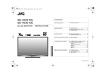
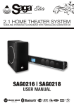
Thank you for choosing the Hogtunes
Big Ultra Kit. Since positive word of mouth is
the best way to grow our business, we want
your new system to work as well as it was
designed to. If you have any questions or
concerns, we are here to help.
DESIGNED
AND
ENGINEERED
IN
CANADA
Email: [email protected]
Tel: 705-719-6361
A video version of this manual is available at
www.hogtunes.com.
If you still need assistance, please
consider a professional installation by
your motorcycle dealer.
INSTALLATION
MANUAL
For Use on 1998 - Current
Ultra Classics*
*Do not install this kit if any external amplifier to the radios built in power
is present. This includes FLHTCUSE “CVO” models with factory amplifier
under the tour-pak!
IMPORTANT: The NCA-40.4 amplifier cannot be used if any external
amplifier is already on the bike. This includes FLHTCUSE CVO Models
with the factory amplifier under the tour-pak!! This kit will work on CVO
models if the factory amplifier and its wiring have been removed.
Harley-Davidson, Electra Glide, Road Glide, Street Glide, Ultra Classic, Tri Glide CVO, Screamin Eagle and
Tour-Pak® are Trademarks, and/or Registered Trademarks of Harley-Davidson, Inc., Milwaukee, Wisconsin,
USA, and if Used or Implied are for Reference Only. There is No Affiliation Between Harley-Davidson, Inc., and
Hogtunes Inc.
Radio Sound® is a Registered Trademark of Radio Sound, Inc., Louisville, Kentucky, USA and is Used for Reference Only. There is No Affiliation Between Radio Sound Inc. and Hogtunes Inc.
Harman Kardon® is a Registered Trademark of Harmon International Industries Inc., and is Used for Reference
Only. There is No Affiliation Between Harman International Industries Inc. and Hogtunes Inc.
MaxxBass® is a Registered Trademark of Waves Audio Ltd., Tel-Aviv Israel. There is No Affiliation Between
Waves Audio Ltd., and Hogtunes Inc.
UltrasoundTM is a Trademark of Hogtunes Inc, Ontario, Canada.
Version 1.1
2
GETTING STARTED
Step #1: Remove the seat, and both wires (+ and -) from the battery.
Step #2: Remove the outer fairing/headlamp assembly. Refer to a service manual
if you need help with this. Note: A towel on the front fender can help
prevent scratches or “dings” from dropped tools or fasteners etc.
Step #3: Take the 2 wires off each front speaker by gently pulling one at a time.
Undo the screws that attach each speaker/grill assembly to the inner
fairing and remove. Gently pull the stock speaker out of each grill assembly.
Step #4: “Clip” the Hogtunes front speakers (Model 902.2-AA) into each grill
assembly. Position your new speaker/grill assembly onto the inner fairing,
and re-attach each one using the OE screws. Although a hand screwdriver
is recommended for this step, make sure these screws are tight! Let the
factory speaker wires hang for now.
this long harness will plug into the empty 4 pin plug on the input harness. It will
only go on one way. The other 4 pin plug on the rear harness will plug into the
“rear out” which is a white connector on the other side of the amp. Locate the 4
pin black plug with black/brown, and black/blue wires. This will plug into the
“front out” on the amp, which is a 4 pin black socket. Note: There is a blue socket
on the amp labeled “bypass out”. This carries the radios built in power (front channels) and although not used in this kit, is there for future expansion.
The amplifier is designed to mount on top of the radio inside the fairing so
when installed, the large factory wire harness that goes across the back of the
speedometer and tachometer will sit in the “trough” or “dish” cut into the top of
the amplifier, as show in Diagram 1.1 below.
Diagram 1.1 (Prototype Amp Shown on 06+ Without “Foot”)
Step #5: Remove each rear speaker grill by undoing the 4 screws on the front of
the grills. Carefully lift up on each speaker and take the 2 wires off by
pulling one at a time from the stock speaker. Put the grills, fasteners, and
speakers aside.
Step #6: Locate the 2ch/4ch switch on the side of the amplifier, and make sure
it is in the “4ch”position. In this position, the amplifiers front and rear
channels are controlled independently by the Ultra radios built in fader.
If the switch is in the “2ch” position, all 4 channels are driven equally,
and although all 4 channels will play, the radios fader will not adjust
front/rear.
Step #7: Locate the 3 position switch on the side of the amplifier marked
“GAIN”, and make sure this switch is in the “+3” position. Since Ultra
radio’s come with a fader, you can use the fader control to adjust front/
rear balance. If you were to run this amp off a 2 channel radio
(no fader) the 2/4 switch would go to the “2” position, and the gain
switch would be used to adjust the volume of what ever is plugged into
the rear channels.
Step #8: The power harness has an 8 pin white plug with 3 red wires, 3 black
wires, and 1 orange wire. Locate this and plug it into the white socket on the
amplifier marked “power”. The input harness has a smaller black 8 pin plug with
smaller gauge wire. Plug this into the black socket on the amplifier marked “hi
level input”. Locate the long “rear speaker”
harness with 8 black wires in it. One end has a white 8 pin connector,
the other end has two 4 pin connectors. One of the 4 pin connectors on
3
CB
MO
DU
LE
There is a black rubber “foot” in the kit. On 2006+ Ultras, the CB module is
mounted on top of the radio on the clutch side. The foot is used to fill the void next
to the CB, so when installed, the amplifier has ample support. On 1998-2005
bikes, or 2006+ bikes with the CB and XM modules, or 2006 bikes with the CB
removed, the foot is not used.
4
AMP PREPARATION
Review the 3 options below, and pick the option best suited for your bike to
prepare the amp to be installed in place.
1) If you have an 06+ Ultra with the CB as shown in Diagram 1.1, the
foot will be installed using supplied screws to the 2 holes on the bottom of the
“brake side” of the amplifier. The foot has an angle cut in it so it will clear the
outer fairing going back on. Make sure the angled portion of the foot sits
adjacent to the angled part of the amp. Place one side of the supplied “hook
and loop” adhesive on the CB Module, trimming it to fit if you like, and the
other side of the “hook and loop” adhesive on the underside of the amplifier.
Please note that most adhesives work best at room temperature or higher and
on clean surfaces. Put the amp in place. You may have to lift up on the large
wire harness that runs across the speedo/tach to get the amp in. There is an
“overhang” built into the foot. The amp is far enough back when the overhang
meets the back of the radio.
2) If you have an 06+ with the CB AND XM Module, or a 98-05
Ultra, place one side of the supplied “hook and loop” across the CB
Module/XM Module or across the top of the 98-05 radio, and the other side
of the “hook and loop” adhesive on the underside of the amplifier. Please note
that most adhesives work best at room temperature or higher and on clean
surfaces. Put the amp in place so the back of the amp is as close to the back of
the speedo/tach as possible, or the outer fairing will not go back on.
3) If you have an 06+ with no CB (or XM) module you will notice a
“bump” that runs from the front to the back of the radio in the center. Take one
side of the hook and loop adhesive, cut it in half , and place each half on either
side of the bump. Place the other side of the “hook and loop” adhesive on
the underside of the amp. Please note that most adhesives work best at room
temperature or higher and on clean surfaces. Put the amp in place so the back
of the amp is as close to the back of the speedo/tach as possible, or the outer
fairing will not go back on.
WIRING THE AMPLIFIER
Step #1: With amplifier in place, take the yellow/black wires on the input
connector of the amplifier, and plug them into the front factory speaker
wires on the clutch side of the bike. They will only go in one way. Take
the brown/black wires on the “front out” connector and plug them into
the front clutch side speaker. They will only go in one way.
Step #2: Take the green/black wires on the input connector and plug them into
the front factory speaker wires on the brake side of the bike. Take the
blue/black on the front out plug, and plug them into the brake side front
speaker. Again, these will only go on one way.
The orange wire is the “remote turn on lead” and tells the amp to turn on
whenever it sees +12v (.5 amp min.). Unplug the center wire (+) on the cigarette
lighter. Plug the orange lead from the amplifier directly onto the lighter using the
female connector. Plug the factory lighter wire to the male “take off” connector
which is part of the amps orange turn on lead.
ROUTING THE MAIN WIRE HARNESS
Step #1: The power/ground harness and rear harness will pass together under
the inner fairing where the main wire harness passes through on the
brake side of the bike. Loosen the tanks “chrome console” and run wires
up and over the gas tank, but under the tanks chrome console. There is
a provision on the front of the tank console for wires to pass.
A
B
Stock Harness and Amplifiers Harnesses
Passing from Fairing to Just in Front of Tank
(Arrow A). Cable Tying the 2 Amp
Harnesses to the Main Bike Harness Just
in Front of the Tank (Arrow B) Allows the
Amp Harnesses to Go Up Towards the Tanks
Chrome Console Easier and Makes for a
Cleaner Install.
When correctly installed, the power and ground wires are the right length to
connect to the battery, and the remaining 8 pin harness is the right length to be
zip-tied to the brake side fender strut. Be sure to run the 8 pin harness UNDER the
air line for the brake side rear shock.
5
6
Step #2: On the 8 pin rear harness “end” you will see 2 pairs of black shorter
wires in a sheath, and 2 pairs of black longer wires in a second sheath.
Put the ends of the shorter wires into the brake side rear speaker box.
These wires will enter where the factory wires enter the rear speaker
box. Plug the factory rear speaker wires into the male wires of the amp
harness-they will only go on one way. Take a Hogtunes rear speaker
(model 117.2-AA) and plug the female connectors of the amp harness
into the speaker. Again, they will only go one way. Repeat this step
using the longer wires on the clutch side of the bike.
Step #3: Once you are confident the wires are correctly attached to the rear
speakers, sit them in place, put the grills back on, and secure the
speakers by reinstalling the 4 screws on each grill.
Attach the amps red wire to the positive (+) battery terminal, and the amps black
wire to the negative (-) battery terminal. The factory battery wires are also
re-installed at this point. Note: when attaching the power and ground wires, it
is always a good practice to do the negative first. When the positive connector
touches the battery, some sparking is normal. This is a function of the capacitors in
the amplifier charging up.
Step #4: Turn the stereo on, and at low volume, test to make sure all 4 speakers
are working. Note: Sound quality is best with the fairing mounted and
secured on the bike. Re-install the seat making sure the amplifiers “+”
and “-” connectors are positioned in such away so they will not bend or
break when the riders weight is on the seat. This is the best time to take
a few minutes to “clean up” the wiring, and secure using supplied
zip-ties.
Before re-installing outer fairing, turn front wheel to
each extreme side making sure any wiring is not
impeding the steering of the motorcycle.
Failure to do so can result in serious injury or death!
Re-install the fairing and your system is now ready to enjoy!
Adjusting the Bass levels: Hogtunes NCA 40.4 Amplifier yields HUGE
bass due to the MaxxBass feature. On Radio Sound radios, around 5-6 “bars” is
all that is needed on the bass level screen. On Harman-Kardon radios, 1-3 bars
past center is what we have found works best. This is a suggestion only. Adjust the
system for what sounds best to you!
7
WARRANTY INFORMATION
Hogtunes speakers are warranted for a period of 20 years to the original purchaser.
Hogtunes Amplifiers are warranted for 1 year from original purchase date. Proof of
purchase is required for all warranty claims. The warranty applies to the original retail
customer, and is not transferable. All Warranty claims must be made through the dealer this
product was originally purchased from. Speakers found to be defective during the warranty
period will be repaired or replaced (with a product deemed to be equivalent) at Hogtunes
sole discretion. Amplifiers will be repaired. Hogtunes complete warranty policy is available
at http://www.hogtunes.com/warranty.html
What Is Not Covered:
1) Any expense related to the removal or re-installation of Hogtunes products.
2) Repairs to these products performed by anyone other than Hogtunes.
3) Subsequent damage to any other components.
4) Any product purchased from a non-authorized Hogtunes dealer.
5) Damage to Hogtunes products due to an accident or collision.
6) Hogtunes Amplifiers with broken or removed “warranty void” stickers.
TECHNICAL SPECIFICATIONS
Hogtunes NCA 40.4 Amplifier
RMS Power at 2 Ohms:
Max Current Draw:
Freq. Response:
Efficiency:
Fuse at Amp:
Amp (only) Weight:
40 watts x 4
< 8 Amps
40hz-18khz
>60%
15 amp
1 KG (2.2 Lbs.)
Hogtunes #902.2-AA Front Speakers
Power Handling:
Frequency Response:
Sensitivity :
Nominal Impedance:
50W RMS-100W Peak
55hz-25Khz
92 dB 1watt/1meter
2.0 Ohms
Hogtunes #117.2-AA Rear Speakers
Power Handling:
Frequency Response:
Sensitivity :
Nominal Impedance:
50W RMS-100W Peak
55hz-25Khz
91 dB 1watt/1meter
2.0 Ohms
Hogtunes products will play much louder than the
Original Equipment, which can be a distraction to the
rider and/or passenger. Please use caution when adjusting,
or playing your stereo at high volume, especially in traffic.
8